
Hitron CODA56 19" 1U Rack Mount
Print Profile(1)

Description
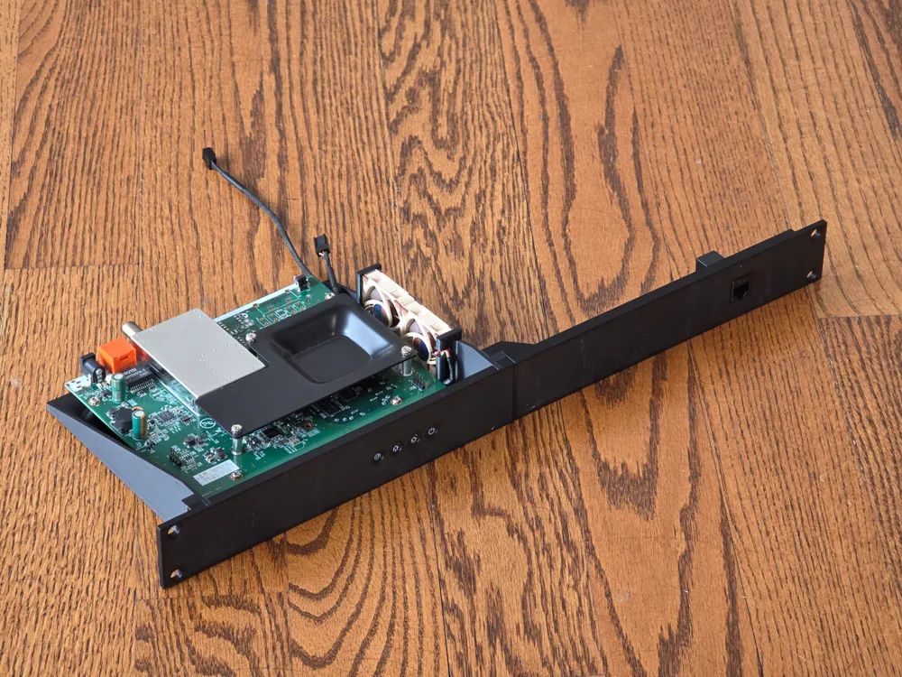
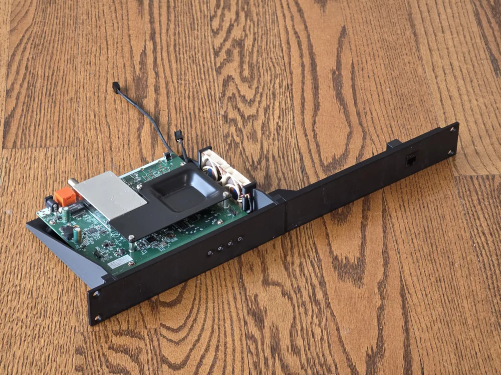
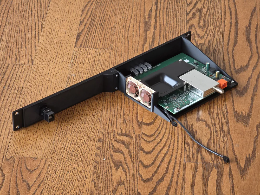
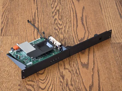
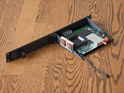
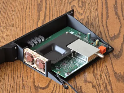
Made this for my own use, and hadn't really planned on sharing until after, so excuse the lack of photos and documentation. This is a 1U, 19" server rack mount for the Hitron CODA56 modem with two fans for active cooling. It isn't perfectly optimized to use minimal material, or to optimize print speed. This is a quick-and-dirty model that I designed simply for my own purposes, printed out of PETG.
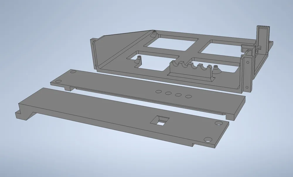
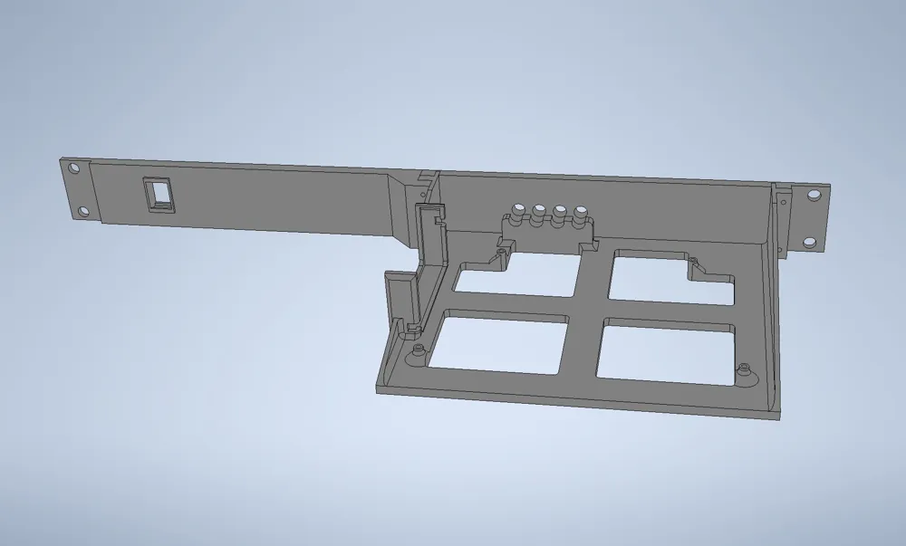
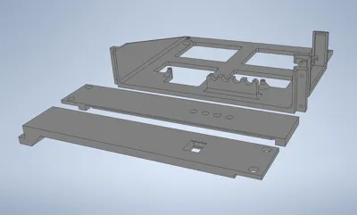
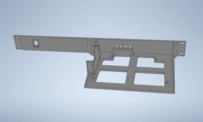
It is printed in 3 pieces: the main “chassis” onto which you mount the CODA56 board/fans, and the front panel, which is split into two halves. Nothing here requires supports with the exception of the one overhang on the right-hand front panel piece. Assembly is as follows:
Hitron CODA56 Disassembly
To remove the board from the OEM Hitron CODA56 enclosure, remove the two screws holding the base in place. Under that you will find two more screws holding the two halves of the enclosure together. Then it's just a matter of prying it apart with your hands - the clips are kind of a pain-in-the-butt to get to snap apart, but with a little patience it will separate. Then just remove the four silver screws securing the board to one half of the enclosure. The other half of the enclosure houses the plastic “light tubes” which illuminate the front panel. Use a small pick or tiny flathead screwdriver to pry up on the clips on each end and it'll pop right out.
Preparing the Light Tubez
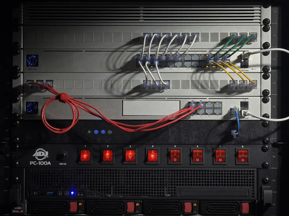
There are many more light tubes than there are lights on this particular modem (there are four), so cut off a section of four lights (cut the thin plastic channel holding them together to create a group of four.) I happen to own a laser engraving machine, so I actually painted the ends of the tubes with black acrylic paint, and then used the laser to burn away the actual icons stolen from the PDF manual. Alternatively you could leave them as solid lights and simply label them separately. Just bear in mind with the board laid flat, the icon order becomes (from left to right): Online, Upstream, Downstream, Power.
Installation and Assembly
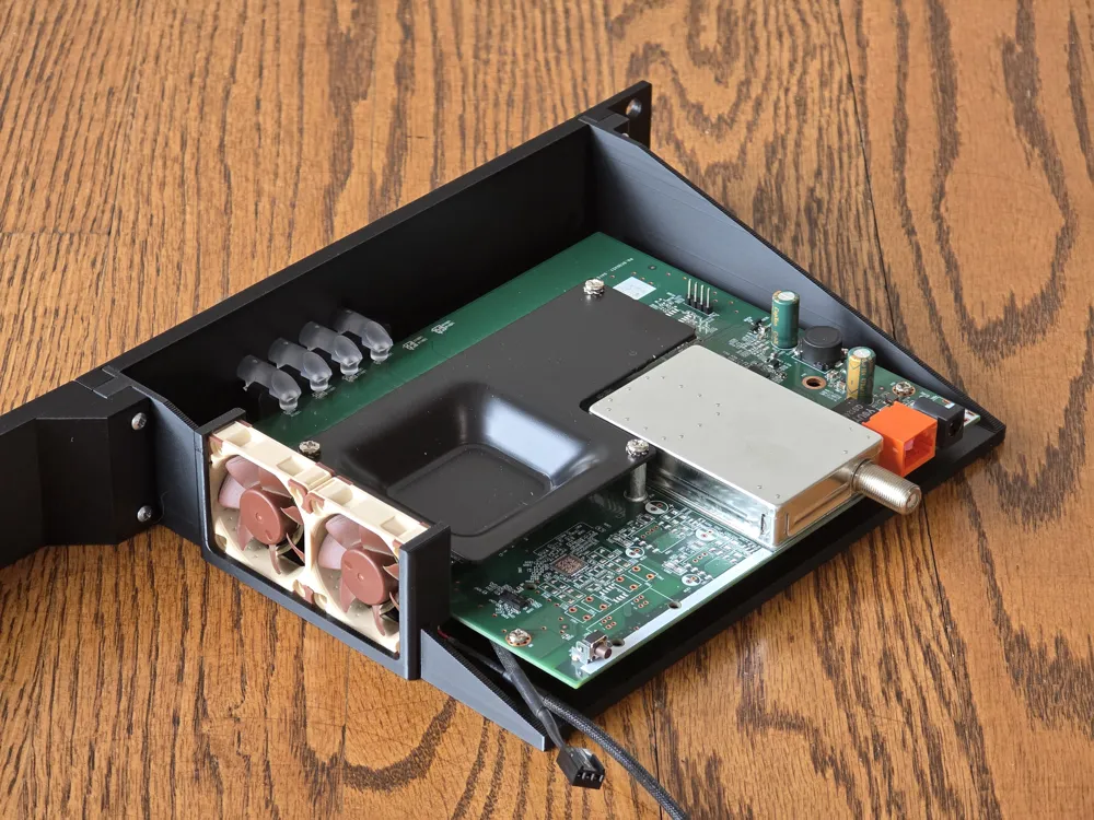
First snap your four light tubes into the little support thingie (the support should hold them BEHIND the little plastic channel that ties them all together). Then secure the faceplates using four #4 pan head screws (two ½", two ¾"), ensuring the light tubes slot into the round holes in the front. Then use the original four silver screws to install the board.
To install the fans, simply slide them into position, paying attention to their orientation to ensure that they blow the right way, AND that the fan cables align with the cutouts. I recommend installing the first fan and sliding it towards the REAR, and then bending the front bracket forward enough to allow you to slide the second fan into position. Depending on the material you print with, you might have less flexibility here and it could snap, so just be gentle. This model is specifically designed to secure two 40mm Noctua NF-A4x10 FLX fans connected together and powered by a 12V, 1.5A power supply.
Lastly snap a pass-through keystone into the right panel and voila!
Notes:
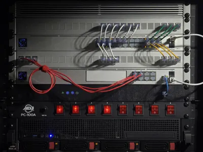
1. This is replacing a 3D-printed rack-mount for an SB8200 modem that I'd actually purchased from someone on Etsy. It was great, but the faceplate was thin enough that it started sagging over time as the plastic twisted. This is why there is a lot of beefed-up area on my faceplates: to hopefully help minimize twisting/sagging over time. However, I still recommend “propping up” the modem tray with something just for added support if there is nothing underneath it. In my case it simply rests on the component below it anyway.
License



Comment & Rating (8)