
Enclosure Base for Advatek PixLite 16 Mk2
Print Profile(1)

Description
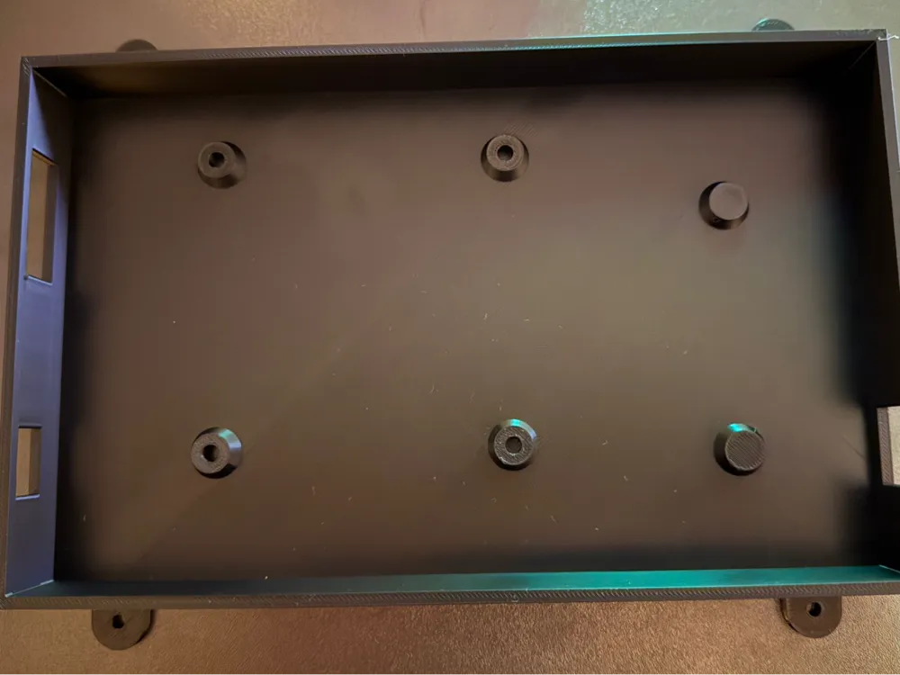
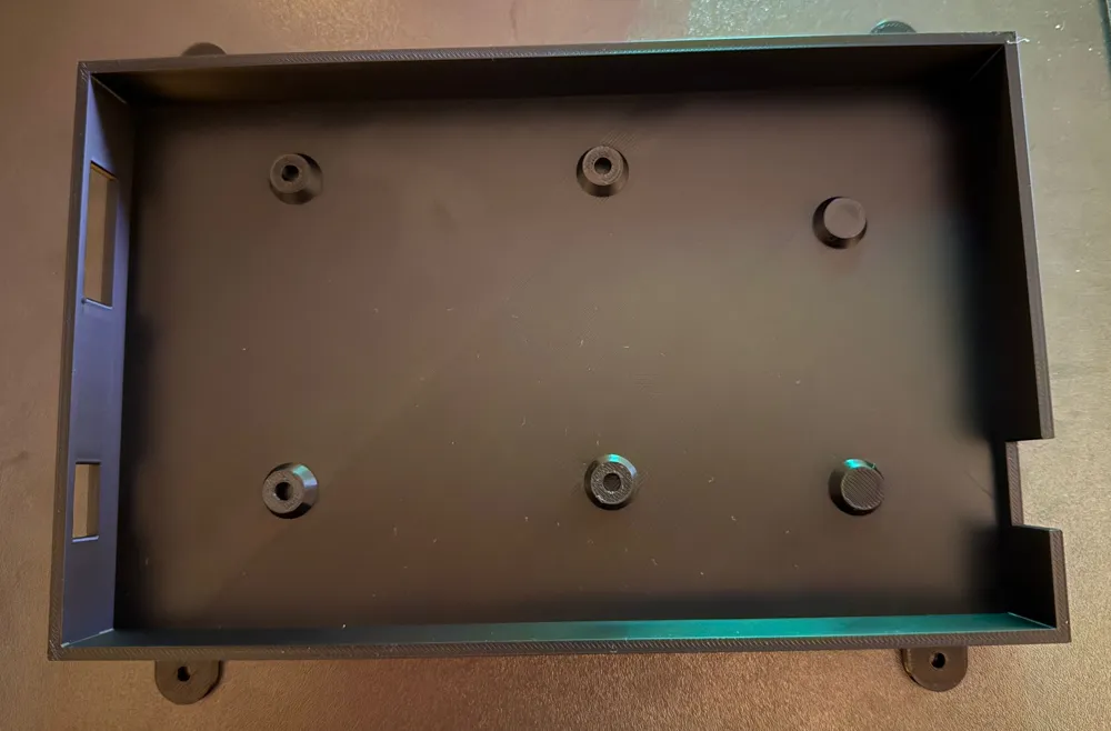
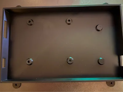
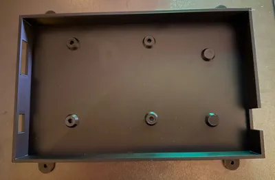
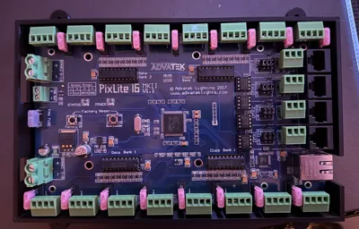
Sturdy enclosure base for the Advatek PixLite 16 Mk2 LED controller.
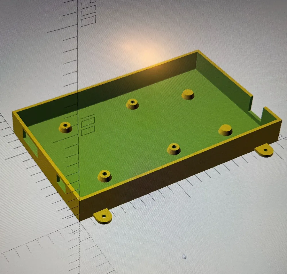
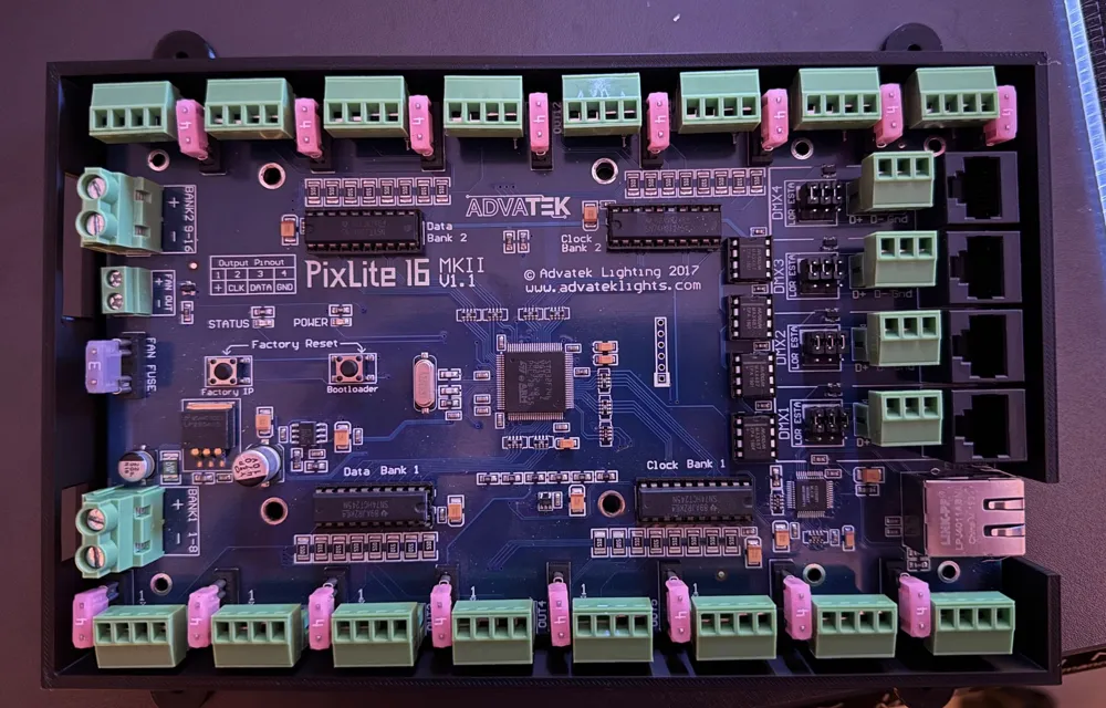
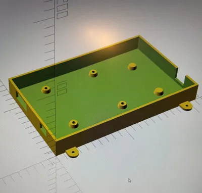
The PCB is mounted on integrated standoffs with M3 heat-set inserts. There is 3 mm clearance around the board, and suitable cutouts for power supply and network are provided. Two additional supports without screw holes stabilize the PCB on the right side. Ideal as a base for a closed enclosure or for installation in a control cabinet.
Features
- Suitable for Advatek PixLite 16 Mk2 (200 × 120 mm PCB)
- 3 mm clearance all around between PCB and inner wall
- Integrated standoffs for M3 heat-set inserts
- Two additional suppports without holes for mechanical stability
- Cutouts for power connections and Ethernet according to original layout
- 4 mounting ears for screwing the base onto a plate or wall
- Fully parametric SCAD design – can be adapted/remixed if needed
Specifications (Model)
- Suitable PCB: Advatek PixLite 16 Mk2, 200 mm (L) × 120 mm (W)
- Wall thickness: 3 mm
- Bottom thickness: 3 mm
- Clearance PCB to inner wall: 3 mm
- Standoff type:
- Hole diameter for M3 heat-set inserts: 4.3 mm
- Top diameter (at the PCB): 10 mm
- Bottom diameter (at the base, „trumpet shape“): 13 mm
- Standoffs precisely aligned according to the measured hole positions of the PCB
- Two additional right supports only as bearing (without screw hole)
(Exact outer dimensions depend on the mounting ears and can be adjusted in the SCAD file.)
Recommended Print Settings
- Technology: FDM
- Material recommendation:
- PETG or ASA/ABS for outdoor use
- PLA only for indoor / test setups
- Layer height: 0.2 mm
- Infill: 20–30 % (Grid/Gyroid)
- Perimeters/walls: at least 3 lines (≈ 1.2 mm)
- Top-/Bottom-Layers: 4–5 layers
- Supports:
- Usually no supports required when the base lies flat
- If your printer has problems with the cable cutouts, activate “Support only from build plate” there
- Print orientation:
- Base flat on the build plate
Required Hardware
- 4 × M3 heat-set inserts for PCB mounting
- 4 × M3 screws (length depending on PCB thickness, e.g. 8–10 mm)
- Optional: Wood screws / sheet metal screws for fastening the mounting ears to the substrate
Notes
- Before final assembly, first make a test print and check the fit of the PCB, cutouts and standoffs.
- If you need another PCB or additional cable glands, you can parameterize/change the SCAD file and upload it as a remix.
Title Suggestion:
Enclosure Base for Advatek PixLite 16 Mk2 (with Standoffs & Cable Cutouts)
Short Description
Sturdy enclosure base for the Advatek PixLite 16 Mk2 LED controller.
The PCB is mounted on integrated standoffs designed for M3 heat-set inserts. There is a 3 mm clearance around the board and dedicated cutouts for power wires and Ethernet. Two additional solid supports on the right side carry the PCB without screw holes. Perfect as a base for a closed housing or for mounting inside an electrical cabinet.
Features
- Designed for Advatek PixLite 16 Mk2 (200 × 120 mm PCB)
- 3 mm clearance all around the PCB to the inner wall
- Integrated standoffs for M3 heat-set inserts
- Additional 2 supports without holes for extra mechanical stability
- Cutouts for power connections and Ethernet according to the original layout
- 4 mounting ears to fix the base to a wall or backplate
- Fully parametric SCAD design – easy to modify and remix
Specifications (Model)
- Compatible PCB: Advatek PixLite 16 Mk2, 200 mm (L) × 120 mm (W)
- Wall thickness: 3 mm
- Floor thickness: 3 mm
- Clearance between PCB and inner wall: 3 mm
- Standoff type:
- Hole diameter for M3 heat-set inserts: 4.3 mm
- Top diameter (at PCB): 10 mm
- Bottom diameter (at floor, „trumpet“ style): 13 mm
- Standoff positions matched to the measured hole pattern of the PCB
- Two extra right-side supports only as mechanical support (no screw hole)
(Exact outer dimensions depend on the mounting ears and can be tuned in the SCAD file.)
Recommended Print Settings
- Technology: FDM
- Material recommendation:
- PETG or ASA/ABS for outdoor or harsher environments
- PLA for indoor use / testing only
- Layer height: 0.2 mm
- Infill: 20–30 % (grid/gyroid)
- Perimeters/walls: at least 3 lines (≈ 1.2 mm)
- Top/Bottom layers: 4–5
- Supports:
- Usually no supports needed when printed flat on the floor
- If your printer struggles with cable cutouts, enable “support from build plate only” for these areas
- Print orientation:
- Base flat on the print bed
Required Hardware
- 4 × M3 heat-set inserts for PCB mounting
- 4 × M3 screws (length depending on PCB thickness, e.g. 8–10 mm)
- Optional: wood screws / sheet metal screws to fix the mounting ears to your panel or wall
Notes
- Always do a test fit with your board and cables before final installation.
- If you need to adapt the design for a different PCB or add more cable openings, simply edit the parametric SCAD file and upload it as a remix.
License



Comment & Rating (0)