


Print Profile(1)

Description
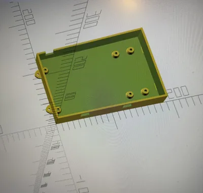
This case bottom is specifically designed for the **SanDevices E682 RGB Pixel Controller**.
The PCB is mounted on trumpet-shaped standoffs with M3 heat-set inserts. At the front, there are two separate cutouts for the power terminals, and at the rear left, an additional slot for cable entry from above.
---
## Features
- **Exact PCB Dimensions**
- PCB Dimensions: 173 mm x 112 mm
- Hole spacing and standoffs match the original PCB
- Trumpet-shaped standoffs, prepared for **M3 Heat-Set Inserts**
- **Front Cutouts for Power Terminals**
- Two separate, rectangular openings at the front
- Dimensions measured with caliper:
- Position of terminals from left or right
- Terminal width approx. 12.8 mm
- A bridge of material approx. 3 mm thick remains above the openings
- **Additional Cable Slot Rear Left**
- Slot in the rear wall, open at the top
- Bottom edge: 8 mm below the bottom edge of the PCB
- Top edge: 15 mm below the bottom edge of the PCB
- Ideal for neat cable entry from above
- **Mounting Tabs ("Wave Ears") Left & Right**
- Organic wave shape similar to the original enclosure
- Hole diameter approx. 3.5 mm for 3 mm screws
- Hole positioned centrally in the outer bead
- **Print-Friendly Design**
- Flat bottom → no supports needed
- Lid can be designed separately later
- Parametric OpenSCAD file: many dimensions can be easily adjusted
---
## Recommended Print Settings
Tested with **Bambu Lab A1** and **PLA Basic**:
- Layer Height: **0.20 mm** (Standard)
- Perimeters/Walls: **at least 3**
- Top/Bottom Layers: **4–5**
- Infill: **20–25 %** (e.g. Gyroid, Grid)
- Material:
- **PLA** for use in dry indoor environments/electrical cabinets
- **PETG** recommended if it can get warmer or slightly humid
- Bed Adhesion: Brim (3–5 lines) depending on print bed
- Orientation: Case bottom with the large, flat side facing down
- Supports: **none**
The holes for M3 Heat-Set Inserts and the 3 mm screws are intentionally kept rather tight. Depending on the printer, slight re-drilling (3.0–3.2 mm) may be useful.
---
## Assembly
1. Print the case bottom and let it cool completely.
2. Melt the **Heat-Set Inserts** into the standoffs with a soldering iron.
3. Place the SanDevices E682 PCB and secure it with M3 screws.
4. Screw the case into the electrical cabinet or onto a mounting plate using the side tabs.
5. Route the power terminals through the front and any other cables through the rear slot.
---
## Notes
- Model is based on measurements with a caliper on the real E682 controller.
- Small deviations due to material and printer calibration are possible.
- For critical fits (standoffs, terminal cutouts, slot), a **test print** with reduced height (only bottom + standoffs) is recommended first.
License: CC BY-NC-SA 4.0 (non-commercial, with attribution)
This case bottom is designed specifically for the **SanDevices E682 RGB pixel controller**.
The PCB is mounted on trumpet-shaped standoffs that are prepared for M3 heat-set inserts. At the front there are two separate cutouts for the green power terminals, and at the rear left there is an additional open-top slot for feeding in a cable from above.
---
## Features
- **Exact PCB dimensions**
- PCB size: 173 mm x 112 mm
- Mounting hole positions and standoffs adapted to the original E682 board
- Trumpet-style standoffs designed for **M3 heat-set inserts**
- **Front cutouts for power terminals**
- Two separate rectangular openings in the front wall
- Dimensions based on real measurements (calipers):
- Position from left / right PCB edges
- Terminal width ~12.8 mm
- A ~3 mm thick material “bridge” remains above the openings
- **Additional rear cable slot (left side)**
- Slot in the rear wall, open at the top
- Bottom of slot: 8 mm below the PCB bottom
- Top of slot: 15 mm below the PCB bottom
- Perfect for routing an extra power cable or data line from above
- **Mounting tabs (“wave ears”) on left and right**
- Smooth, organic wave shape similar to the original enclosure
- Hole diameter ~3.5 mm for 3 mm screws
- Hole positioned in the center of the outer bulge
- **Print-friendly design**
- Flat bottom → no supports required
- Lid/top can be designed separately
- Parametric OpenSCAD source file: many dimensions can be tweaked easily
---
## Recommended print settings
Tested on a **Bambu Lab A1** with **PLA Basic**:
- Layer height: **0.20 mm**
- Perimeters: **3 or more**
- Top/bottom layers: **4–5**
- Infill: **20–25 %** (e.g. gyroid or grid)
- Material:
- **PLA** for indoor use / electrical cabinet
- **PETG** recommended for slightly higher temperatures or humidity
- Bed adhesion: brim (3–5 lines) if needed
- Orientation: case bottom flat on the build plate
- Supports: **none**
The holes for the M3 heat-set inserts and the 3 mm screws are intentionally on the tighter side. Depending on your printer and material you may want to clean them up with a 3.0–3.2 mm drill bit.
---
## Assembly
1. Print the case bottom and let it cool completely.
2. Install the **M3 heat-set inserts** into the standoffs using a soldering iron.
3. Mount the SanDevices E682 PCB using M3 screws.
4. Fix the case in your cabinet or on a mounting plate using the side tabs.
5. Route the power terminals through the front openings and any additional cable through the rear slot.
---
## Notes
- This model is based on physical measurements with a caliper directly on a real E682 board.
- Minor deviations due to printer calibration and material shrinkage are possible.
- For critical fits (standoffs, front cutouts, rear slot), it’s a good idea to print a **short test piece** (just bottom + standoffs) before printing the full-height part.
License: CC BY-NC-SA 4.0 (non-commercial, with attribution)
Comment & Rating (0)