Two Team Quiz Game


Print Profile(0)
Description
Boost Me (for free)
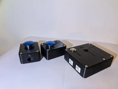
This is quite a large project that I decided to take on because I had most of the stuff laying around the house, and because a friend wanted a game buzzer for an event they were hosting. It is fairly simple and assembly isn't hard at all but will take some time and soldering! It's worth it for the hours of enjoyment it will provide!
Print the player box twice, and all other parts once! The 9volt battery door will be a nice snug fit! Print 3 of this part for your LEDs: https://makerworld.com/en/models/90914-5mm-led-lights-cap
Parts You'll Need: (links for convenience)
2xEthernet Patch cables
2x22mm Mushroom momentary push button switches
13x#6x32x1/2inch Phillips flat head machine screws
1x5mm LED common Cathode BiColor LED
1x12mm Latching push button switch (Power button)
1x16mm momentary push button switch
3 feet Ethernet or connector wire
1x9V battery
4xM1.4x4mm screws (for securing arduino)
2xM3x5mm screws (for buzzer)
At least 2x 330 ohm resistors is helpful to dim LEDs but not required
Solder and Soldering Iron
Assembly Help:
Please note these instructions assume some basic electronics understanding, like identifying the annode and cathode on an LED.
Player Buttons:

- Use some CYA glue to glue the LED Holder into the 7mm hole in the side of each player button.
- Insert (screw down) the 22mm momentary pushbuttons into the lids.
- Use a punch down tool to place Orange and White/Orange wires about 4 inches long into the RJ45 keystones (X2) B configuration.
- Use a punch down tool to place Green and White/Green wires about 4 inches long into the same RJ45 keystones (X2) B configuration..
- Strip a little of the insulation from the ends of all of the wires, screw the Orange wire end under one terminal of the 22mm push button. Screw the White/Orange wire under the other terminal of the 22mm push button.
- Snip off the extra length from the LED leads so that about 5mm (instead of ~30mm) is exposed. Solder the White/Green wire to the cathode (usually flat) side of a 5mm LED. Solder the Green wire to the annode(positive) side of the LED.
- Place the LED into the holder glued into the base in step 1 and add a dab of glue.
- Snap the RJ45 keystone jack into the base and carefully stuff the wires into the box.
- Screw the lids on with #6-32x1/2inch machine screws.
- You should have two player button modules assembled and ready to use!
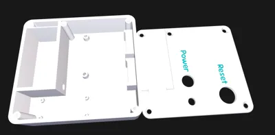
Host Box:
[graphics coming soon]
- Program your Arduino Nano with the code found below.
- Glue an LED Holder into the 7mm hole in the lid.
- Secure the 16mm momentary reset push button into the hole labeled “Reset” in the lid. Secure the 12mm latching button into the hole labeled “Power” in the lid.
- Place a 9v battery clip into the battery compartment of the base. Make sure to place the wires into the main box thought the hole in the side of the battery compartment.
- Solder the Black lead from the latching power switch to the Red lead from the battery clip. Wrap the connection with some electrical tape.
- Solder the Red lead from the latching power switch to “VIN” on your Arduino Nano. It's best to poke it into the top and solder on the bottom side of the board.
- Solder the Black lead from the battery clip onto the Nano in the “GND” next to the VIN.
- Solder the Red wire from the Buzzer to D11 on your Nano. (Don't worry we will connect the black wire later!)
- Don't solder anything to D10 (yeah just skip it!)
- Solder ~6inches of a Green wire to D9 on your Nano. This will be P1. Punch the other end of this Green wire into an RJ45 keystone jack as well as a White/Green wire of the same length (Remember B configuration, and don't worry, we will connect the lose end of this wire later!)
- (Different but close to the same as 10:) Solder ~6inches of a Green wire to D8 on your Nano. This will be P2. Punch the other end of this Green wire into the second RJ45 keystone jack as well as a White/Green wire of the same length (Remember B configuration, and don't worry, we will connect the lose end of this wire later!)
- Identify the red and green legs of a Bi-Color LED. (For me green had 45° bends and red had 90° bends.) GND is in the middle. Clip the excess from the leads. If you wish solder a ¼ watt 330 ohm resistor to the GND pin of the LED. Solder ~4 inches of White/Green wire to the GND pin or other side of your resistor. (Don't worry we'll connect the loose end later!) Solder ~4 inches of White/Brown wire to the “green” leg of the LED. Solder ~4 inches of Brown wire to the “red” leg of the LED. Wrap with tape/heat shrink/liquid electrical tape to ensure no grounding or cross connecting happens.
- Solder the White/Brown wire (from step 12) to D7 of your Nano. Solder the Brown wire (from step 12) to D6 of your Nano.
- Solder a Blue wire ~6inches to D5 of your nano. Secure the loose end to one side of the 16mm reset switch. Secure ~6inches of White/Blue wire to the other screw of the 16mm reset switch which we will connect later.
- If you wish solder the two White/Green wires from your RJ45 to one side of a 330 ohm resistor. The other end we will secure later.
- Connect ~6inches of Orange wire to D4 and punch it down into the P1 RJ45 connector in the B configuration (The Green wire attached to D9 should be in this same keystone jack). Punch down ~6inches of White/Orange wire into this same connector to be connected later.
- Connect ~6inches of Orange wire to D3 and punch it down into the P2 RJ45 connector in the B configuration (The Green wire attached to D8 should be in this same keystone jack). Punch down ~6inches of White/Orange wire into this same connector to be connected later.
- Solder ~2inches of White/Brown wire to the GND between D2 and RST.
- Time to start securing parts. Secure the Arduino Nano into the box with M1.4x4mm screws with the usbc port toward the more accessible/ open side in case you need to reprogram if you want to change the buzzer sound for instance. Secure the RJ45s into the keystone ports. Secure the buzzer to the box.
- Now the moment you've been waiting for… all those loose ends. (6 or 7 depending on if you added a resistor.) Solder them together and wrap them in tape or use a small wire nut to protect shorting from happening.
- Tuck everything into the box carefully. Connect a 9-volt battery and test all connections… connect the player buttons with patch cables. If something doesn't work, time to troubleshoot and fix it. If all is good, secure the lid and battery door.
- Play away!
The Arduino Nano Code:
// --- Pin Setup ---
const int btnP1 = 3;
const int btnP2 = 4;
const int btnReset = 5;
const int ledP1 = 8;
const int ledP2 = 9;
const int buzzer = 11;
// Status LED (common cathode red/green)
const int statusRed = 6;
const int statusGreen = 7;
// --- Debounce Settings ---
unsigned long lastDebounceP1 = 0;
unsigned long lastDebounceP2 = 0;
unsigned long lastDebounceReset = 0;
const unsigned long debounceDelay = 30;
// --- State ---
bool gameLocked = false;
void setup() {
pinMode(btnP1, INPUT_PULLUP);
pinMode(btnP2, INPUT_PULLUP);
pinMode(btnReset, INPUT_PULLUP);
pinMode(ledP1, OUTPUT);
pinMode(ledP2, OUTPUT);
pinMode(buzzer, OUTPUT);
pinMode(statusRed, OUTPUT);
pinMode(statusGreen, OUTPUT);
resetGame(); // start in READY state
}
void loop() {
int readingP1 = digitalRead(btnP1);
int readingP2 = digitalRead(btnP2);
int readingReset = digitalRead(btnReset);
// RESET button
if (readingReset == LOW && (millis() - lastDebounceReset) > debounceDelay) {
lastDebounceReset = millis();
resetGame();
}
if (gameLocked) return;
// PLAYER 1
if (readingP1 == LOW && (millis() - lastDebounceP1) > debounceDelay) {
lastDebounceP1 = millis();
player1Buzz();
}
// PLAYER 2
if (readingP2 == LOW && (millis() - lastDebounceP2) > debounceDelay) {
lastDebounceP2 = millis();
player2Buzz();
}
}
void glideTone(int startFreq, int endFreq, int duration) {
int steps = 20; // number of frequency steps
int freqStep = (endFreq - startFreq) / steps;
int stepTime = duration / steps;
for (int i = 0; i < steps; i++) {
int f = startFreq + freqStep * i;
tone(buzzer, f);
delay(stepTime);
}
tone(buzzer, endFreq); //extend the ending tone
delay(150);
noTone(buzzer);
}
void player1Buzz() {
gameLocked = true;
digitalWrite(ledP1, HIGH);
glideTone(1200, 400, 350); // start high, glide down
showRed();
}
void player2Buzz() {
gameLocked = true;
digitalWrite(ledP2, HIGH);
glideTone(400, 1200, 350); // start low, glide up
showRed();
}
void resetGame() {
gameLocked = false;
digitalWrite(ledP1, LOW);
digitalWrite(ledP2, LOW);
noTone(buzzer);
showGreen();
}
// --- Status LED (COMMON Cathode (NEG)) ---
// ON = HIGH, OFF = LOW
void showRed() {
digitalWrite(statusRed, HIGH); // red on
digitalWrite(statusGreen, LOW); // green off
}
void showGreen() {
digitalWrite(statusRed, LOW); // red off
digitalWrite(statusGreen, HIGH); // green on
}
Comment & Rating (0)