
A1/A1mini extruder, extruder gear temperature-controlled cooling fan and five-way protection (non-destructive installation)
Print Profile(1)

Description
As the weather gradually turned cold, I splurged 132 RMB on PDD to buy a side-opening ventilated cat villa, measuring 60cm wide, 60cm deep, and 90cm high as shown in the picture, to enclose the A1 for thermal insulation.
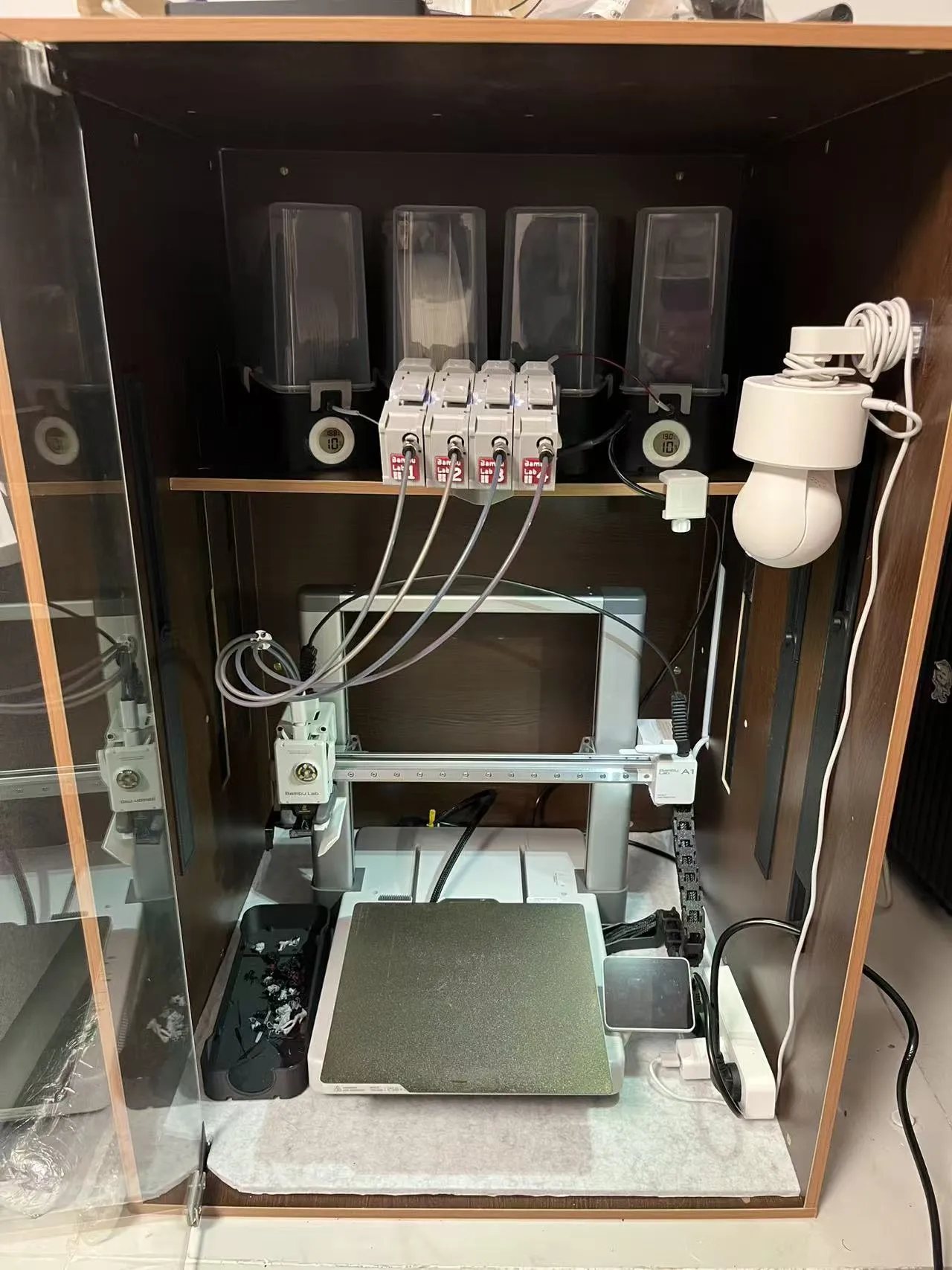
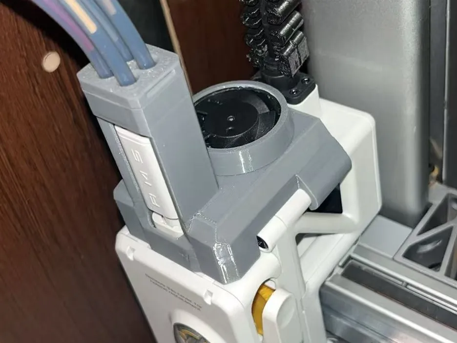
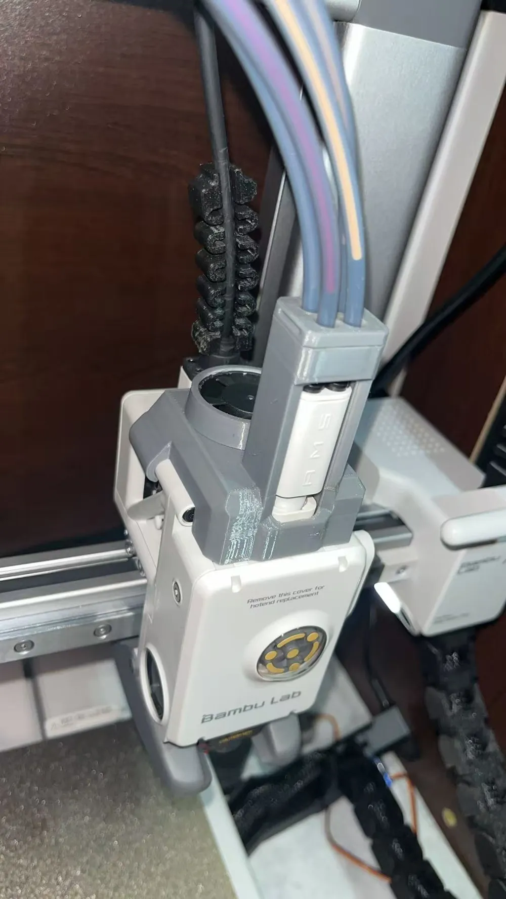
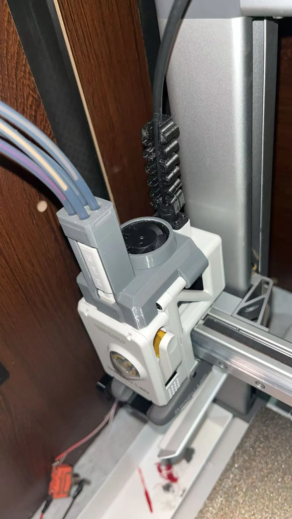
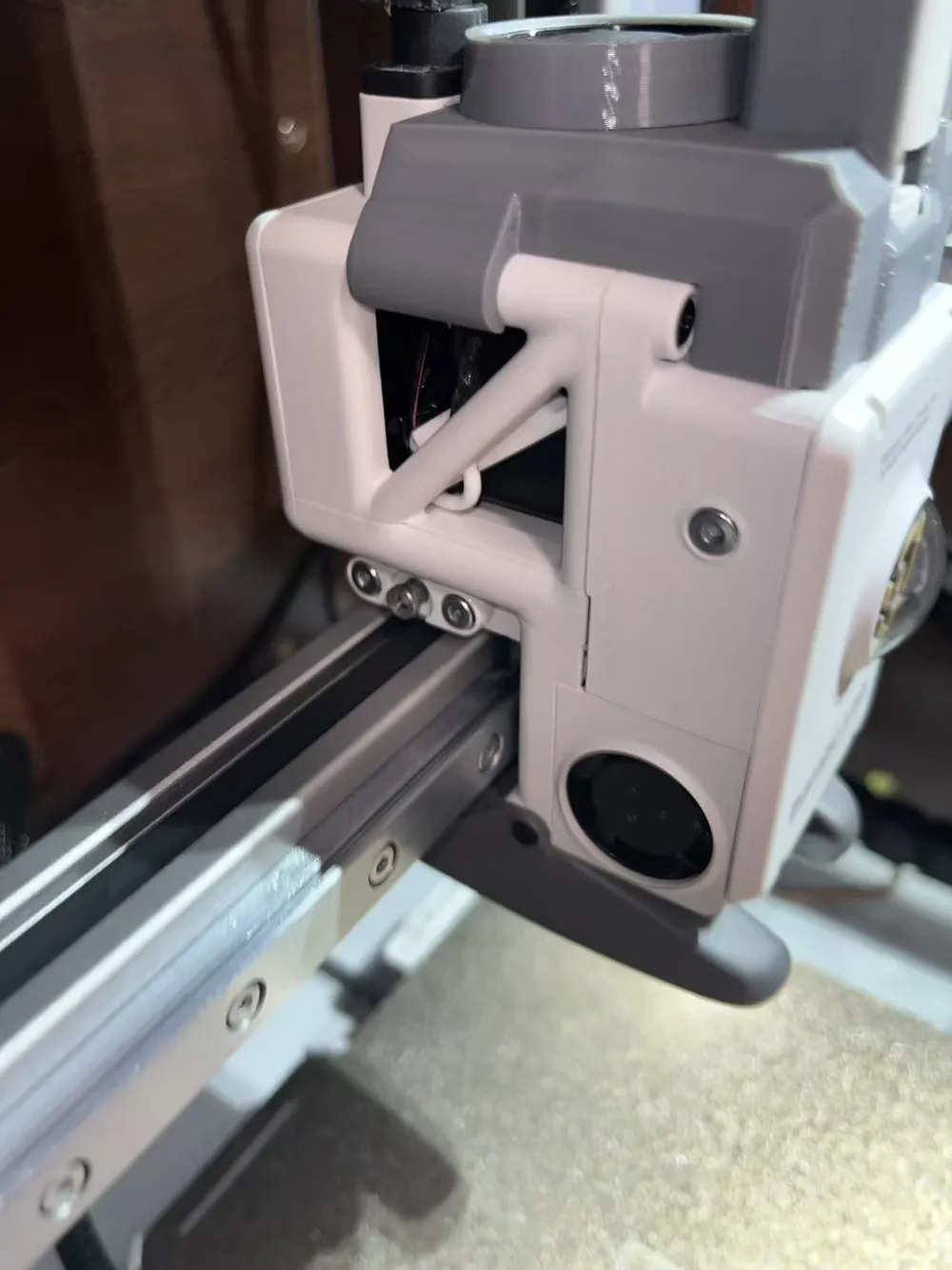
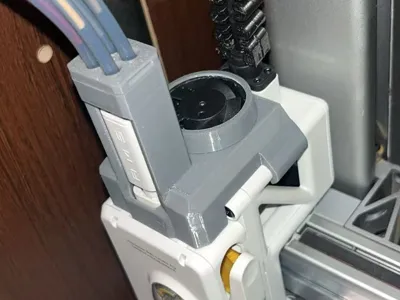
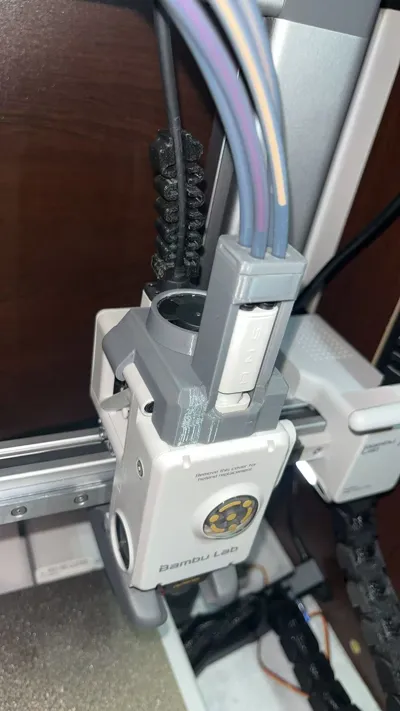
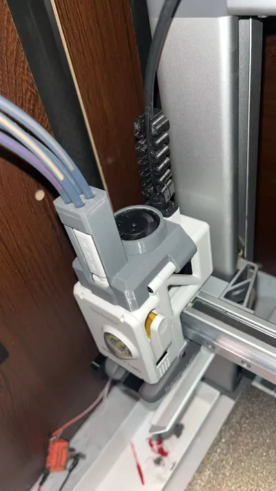
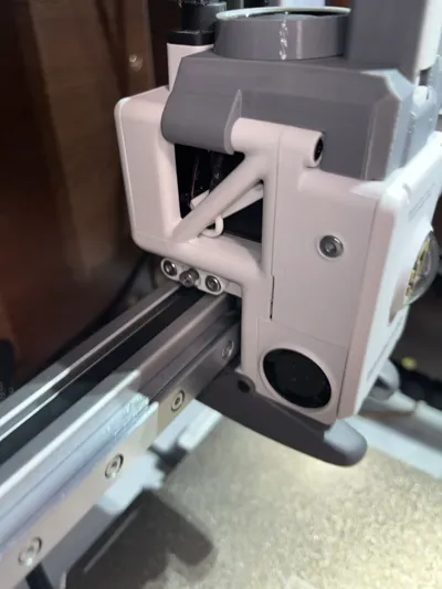
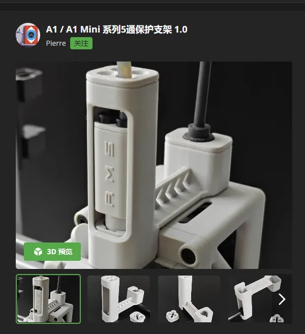
To address the issues of excessive extruder temperature after enclosure and the risk of the five-way connector bursting due to PTFE tube displacement, this three-in-one bracket for the extruder motor, extruder gear cooling, and five-way protection was designed.
This bracket solves the current pain point that five-way protection and extruder cooling fans cannot be installed simultaneously. It offers advantages such as temperature control, lightweight design, non-destructive installation, and optional built-in/external power supply solutions.
Replication requirements:
1. Involves disassembly and installation of the extruder back cover and mainboard, requiring certain hands-on skills. Welding carries some risk, and common tools such as soldering iron, electrical tape/heat shrink tubing, and flush cutters are needed.
2. For modifications involving AMS (24V power supply), 12VDC external power supply, 5V external power supply, etc., please design the power supply yourself (refer to other extruder cooling solutions for power supply options). For aesthetics and lightweight design, the author chose to install using the extruder's built-in power supply.
Materials required:
1. 5v 3010 round fan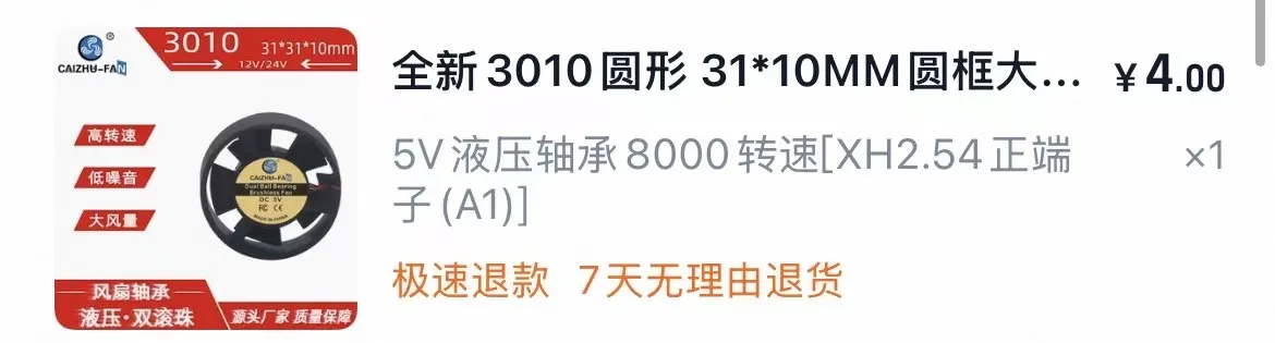
2. Ceramic perforated temperature control switch; choose the switch temperature yourself, as too low a setting may prevent the fan from stopping in summer.
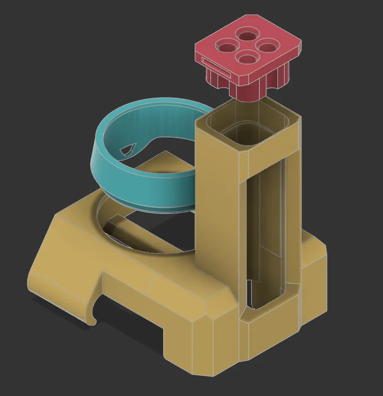
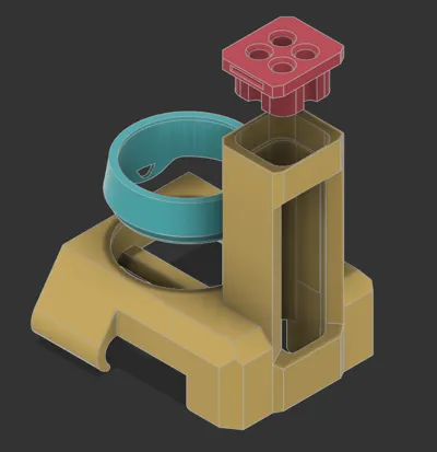
3. Printed parts as shown in the figure.
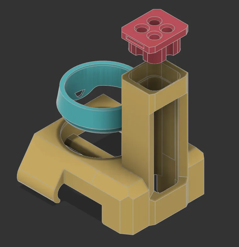
Printing Notes: The base is printed as a single piece, using different filaments as support to ensure a good top surface finish. For the interlayer strength of the main part, 100% infill is used. Also, a high flush volume is set during filament changes. If the nozzle is not clean, it is very likely to cause clogging (sad). Please clean it well or keep an eye on it during filament changes. If you don't have AMS, it is recommended to use default support parameters with additional settings (top Z distance 0.12, top contact Z distance as small as possible (smaller means better effect but harder to remove), support/model XY separation 0.5).
Installation steps:
1. Shorten the round fan terminal wire, leaving about 10cm, then thread it through the fan bracket mounting hole and install the fan (a drop of glue can be used on the bracket for permanent fixation). Then, install the fan bracket onto the base as shown in the picture above.
2. Remove the extruder Type-C connector cable, extruder backplate, all connections, and the mainboard (refer to Bilibili for 'A1 series extruder cooling kit installation video'). Remove all PTFE tubes connected to the five-way connector.
3. Rotate the fan base so that the fan wire can smoothly pass through one of the two openings at the top of the extruder. Then, slide the installed fan base into place from the five-way connector.
4. Solder one of the fan's positive or negative wires to the temperature control switch and solder the cut original fan terminal wire (refer to the final installation diagram to gauge the length for installation) to the other end of the temperature control switch. Remember to insulate properly with heat shrink tubing or electrical tape. The other fan wire should also be soldered using an original terminal wire (remember to estimate the length).
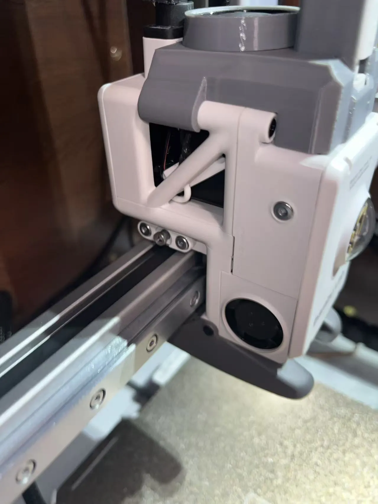
5. Secure the temperature control switch as shown in the figure below (use the thicker original wire of the temperature control switch to wedge it between the extruder frame and the temperature control switch). This method has been tested and is very secure.
6. Break off the plastic head of the fan terminal wire with flush cutters and extract the metal pin.
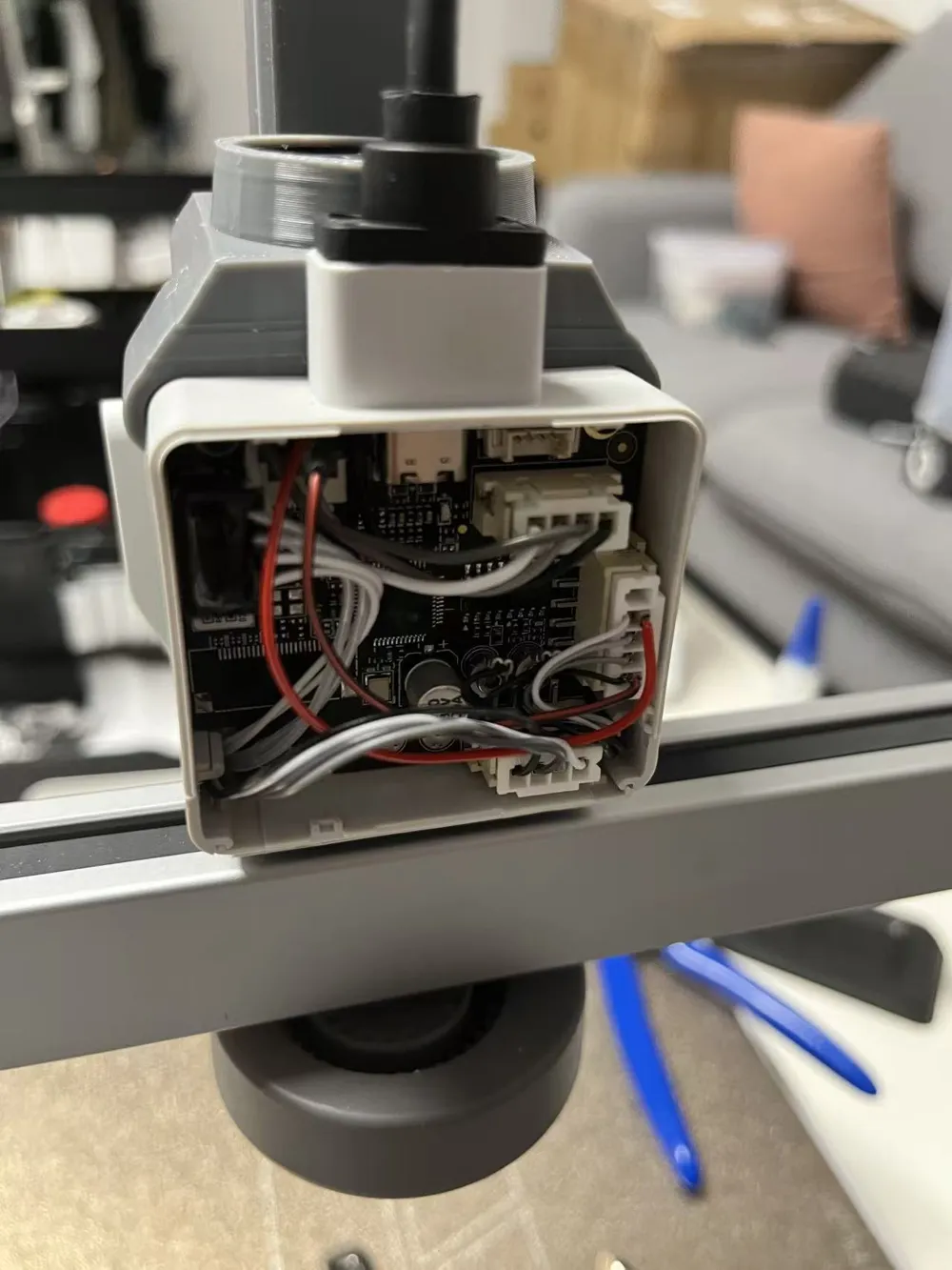
7. Route the terminal wire out from the notch in the ribbon cable at the upper left corner of the mainboard, then re-install the mainboard and other ribbon cables.
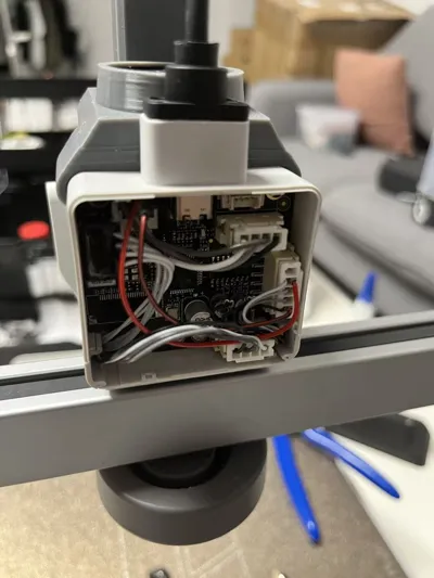
8. After trimming the metal pin of the terminal wire (trim it so it can be inserted and requires slight force to pull out; the cover plate will hold it in place once installed), insert it into the original fan port as shown in the figure 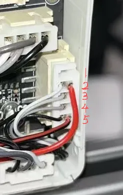 (the rightmost port has five wires: connect the fan's positive red wire to port #2 as shown, and the fan's negative black wire to the bottommost port #5). Once in place, re-install the connector cables and the rear cover plate, install the five-way protection head cover plate, and insert the PTFE tube to complete the installation.
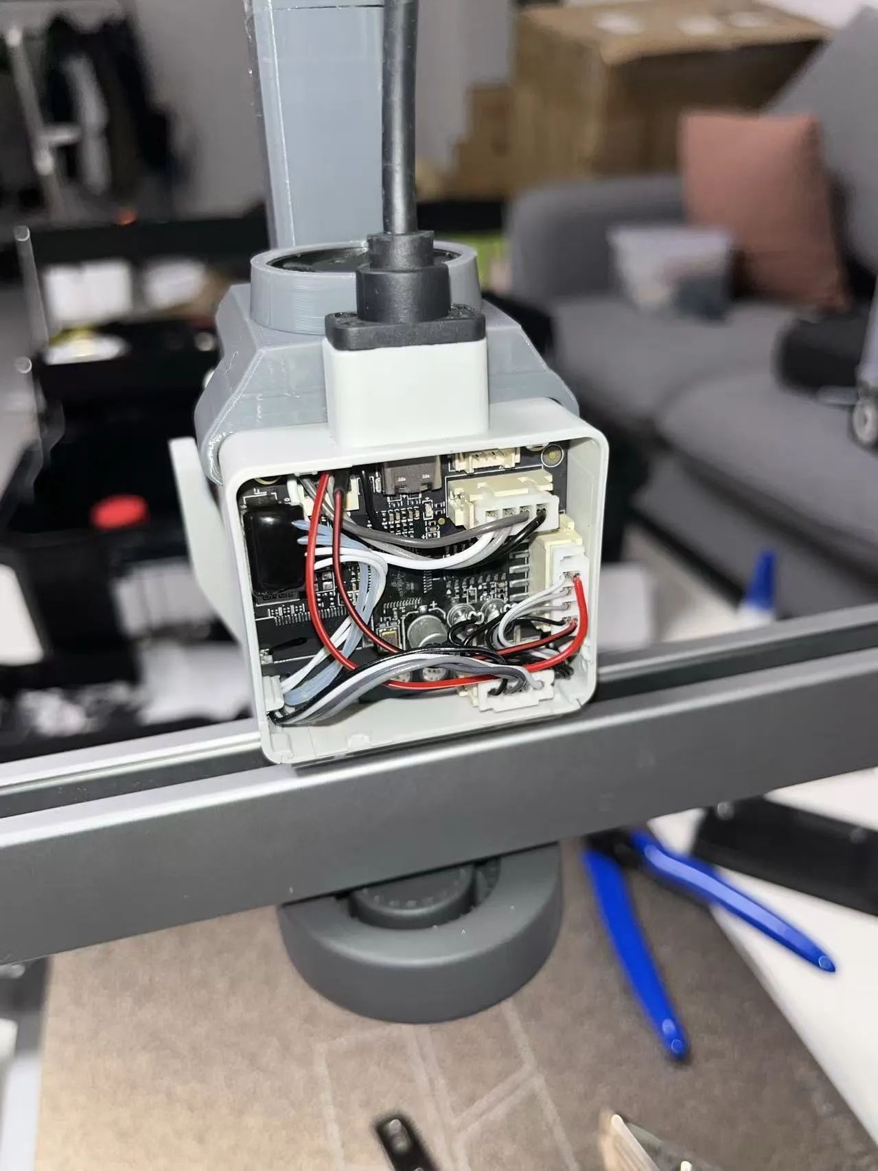
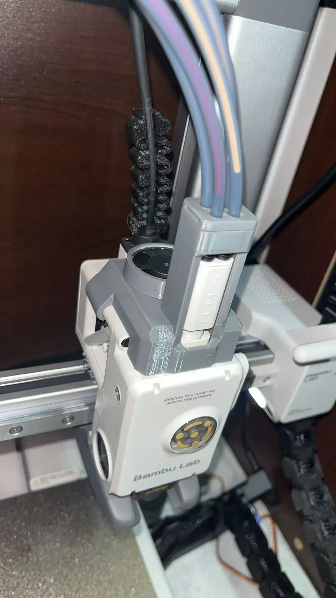
Installation effect:
Thanks to the following authors for providing inspiration and data for this model:
1.
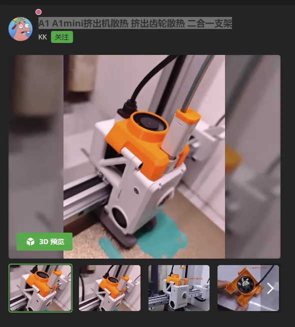
2.
Enclosure solution related:
1.606090 PDD Cat Villa Enclosure Adjustable Vent Plug/Seal
2.BMCU606090 Cat Villa/Cat Bed Partition Rotating Bracket
License



Comment & Rating (1)