
CyberBrick Control Panel
Print Profile(1)

Bill of Materials


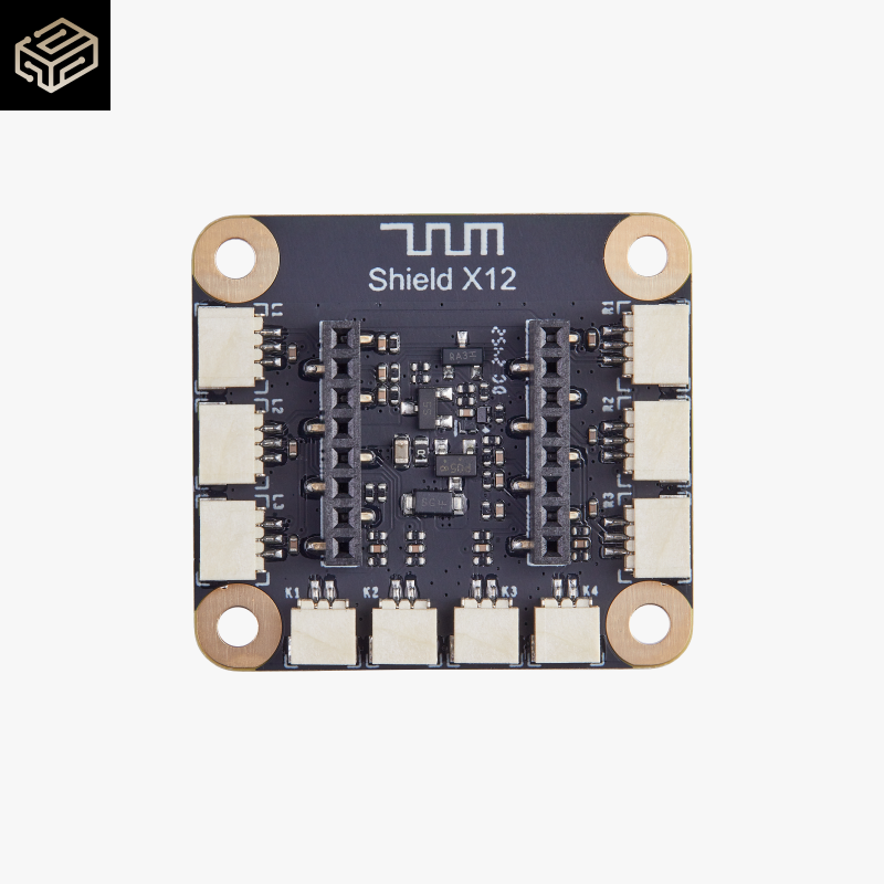
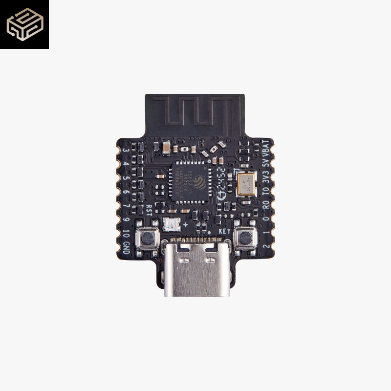
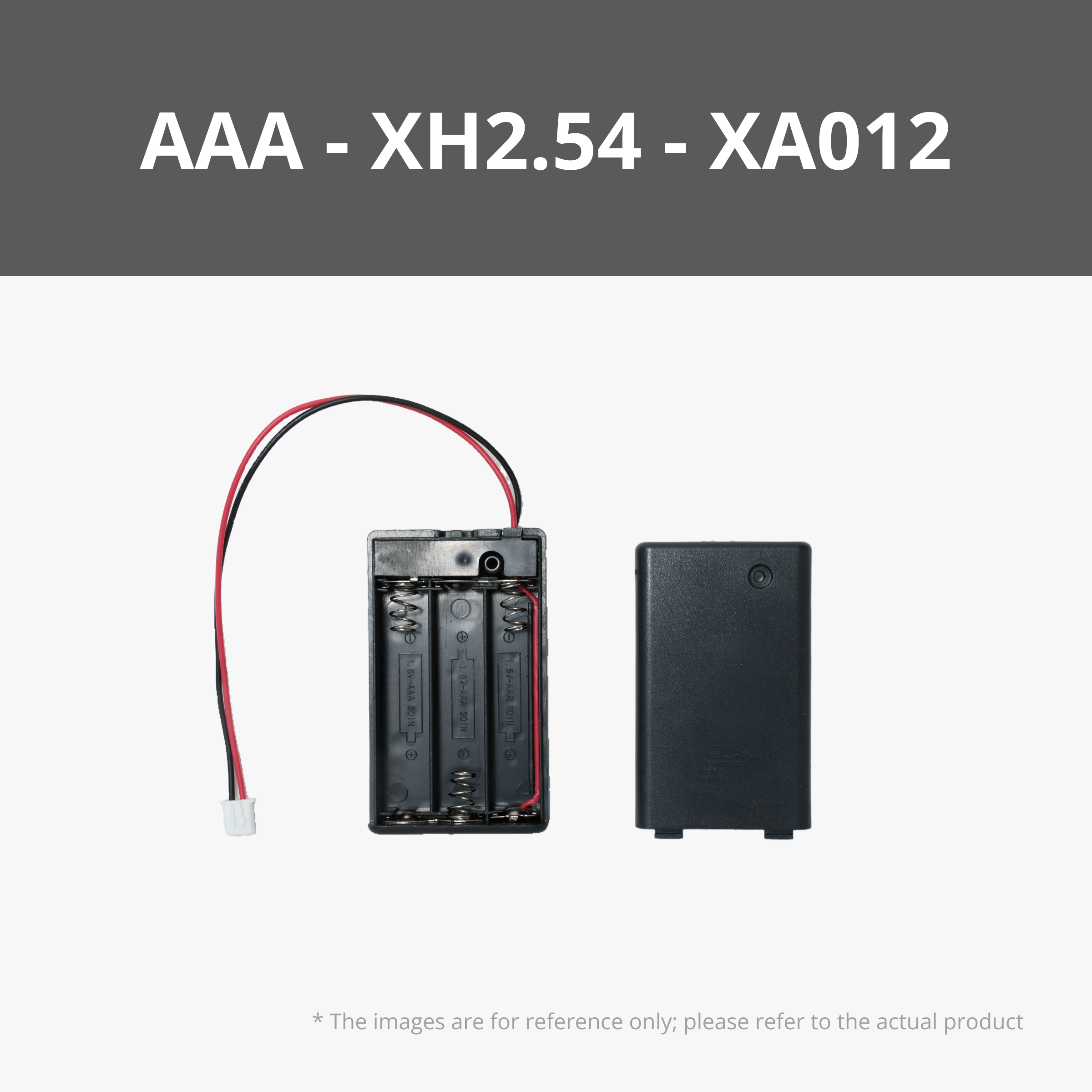


Description
Download my newest model here! ;) https://makerworld.com/en/models/2964414
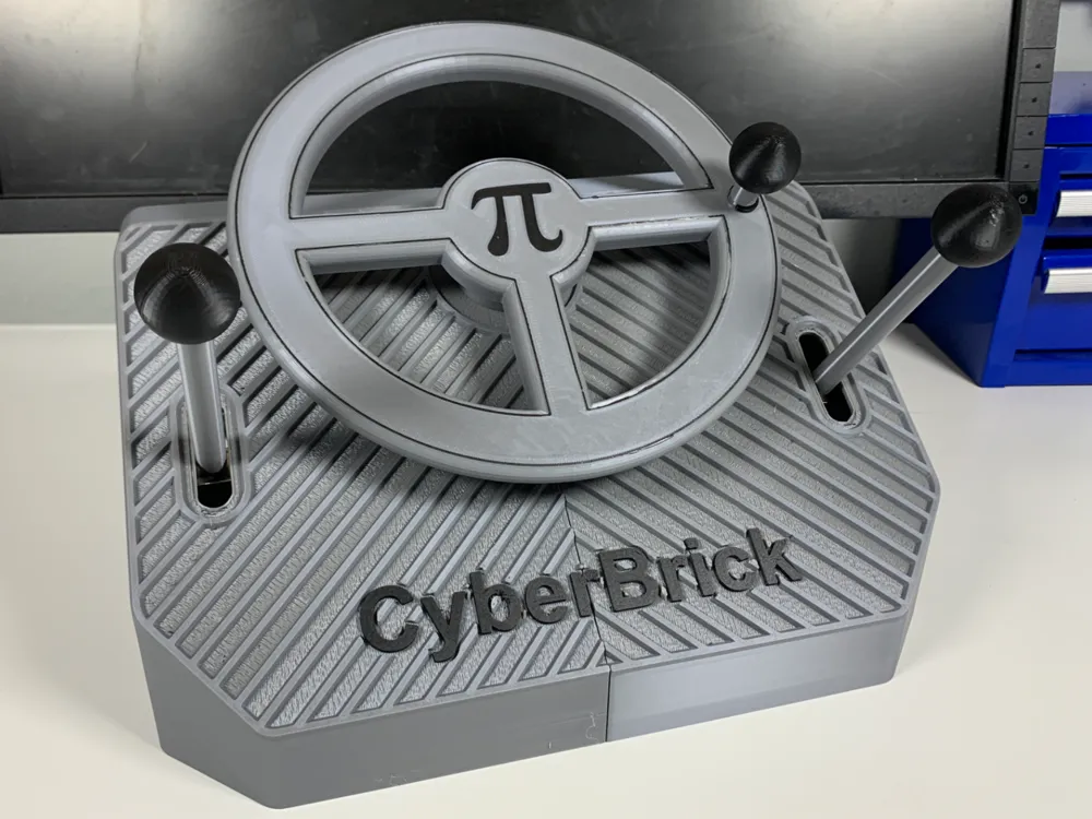

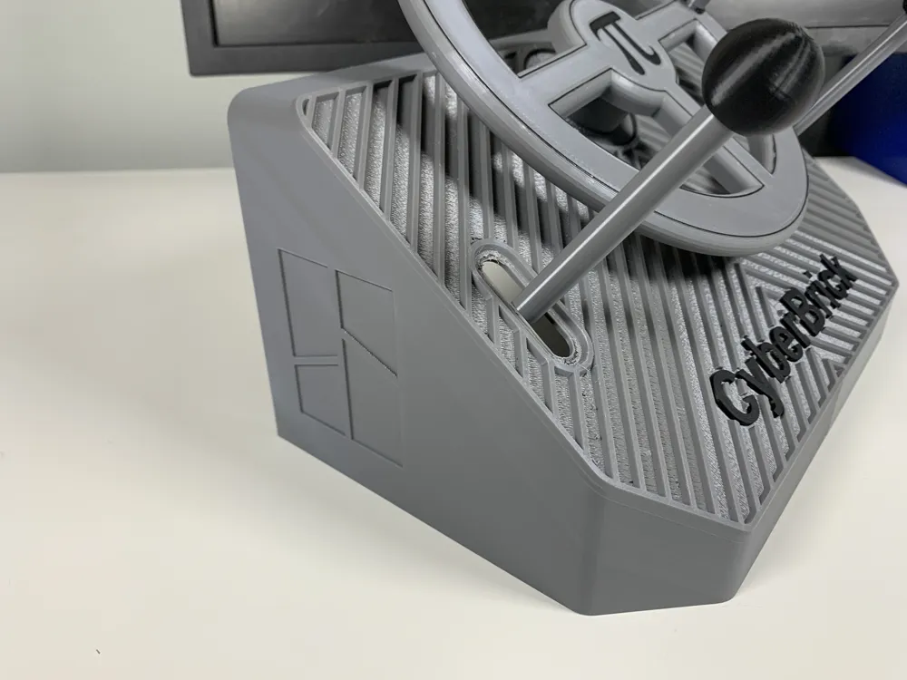
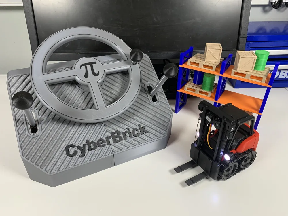
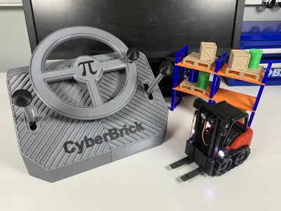
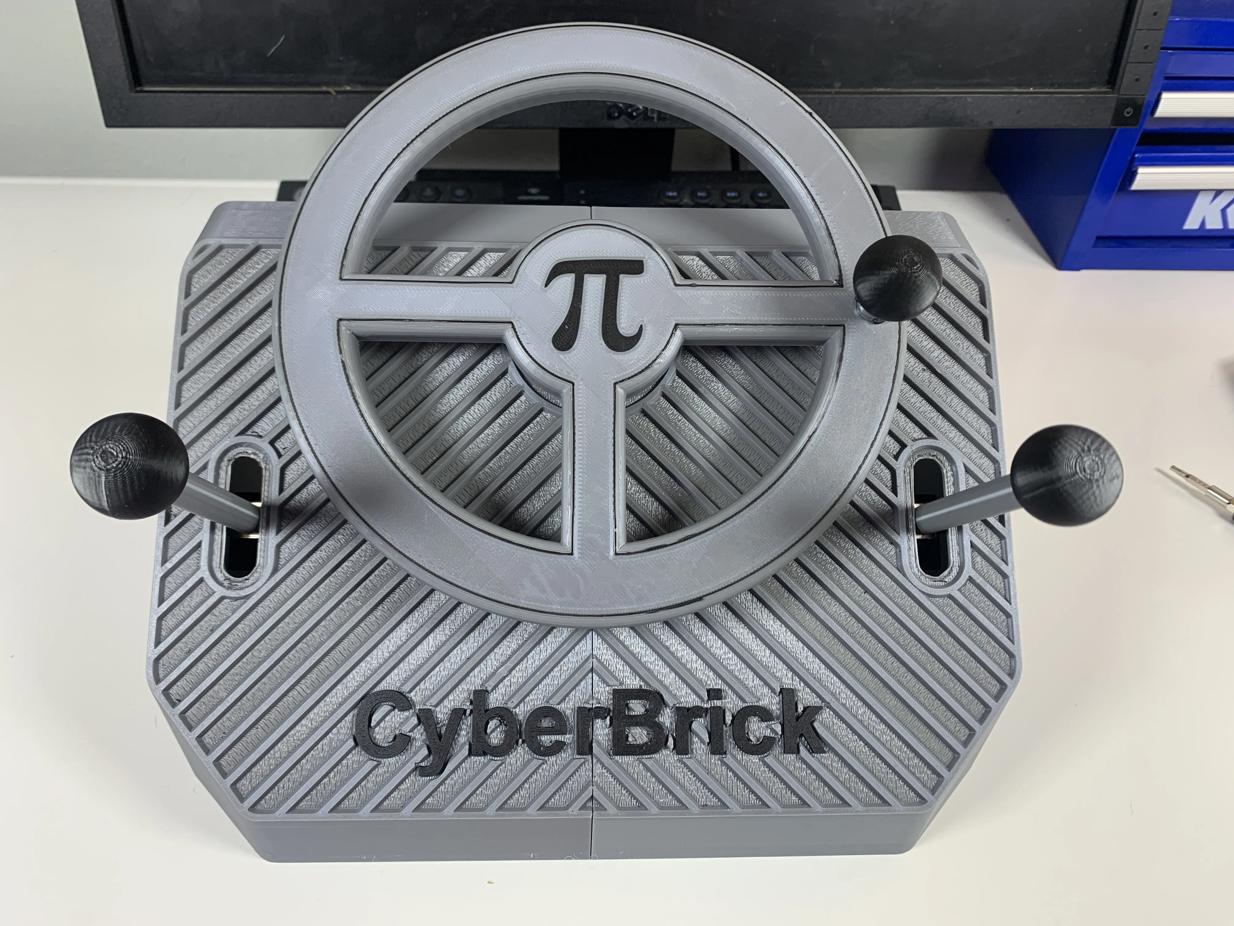
CyberBrick Control Panel for Forklift
When I first built my CyberBrick forklift, I was super proud of how realistic it turned out — every little movement, every detail! But once I started using it, I noticed one big problem: the forklift and truck felt real, but the controller didn’t. It just didn’t match the experience.
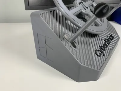
So, I decided to build my own control panel from scratch. I wanted it to feel like sitting in a real vehicle — with proper levers and smooth controls that make sense! After a TON of testing and tweaking, I got it working exactly how I wanted!
Now, when driving the forklift and truck, it feels totally different. The movements are super precise, the controls are satisfying, and the whole thing just feels way more realistic. Now it’s the closest thing you can get to the real deal!
This model is designed for use with the CyberBrick Official Forklift https://makerworld.com/en/models/1395994
Or for use with the CyberBrick Official Truck https://makerworld.com/en/models/1396031
Boost Me (for free)
Models like this take a lot of time (and filament) to create. 🧵
Since 1 Boost = 70g of Bambu Lab filament, your support goes directly into making more prototypes! 🚀
Boosting me is a fantastic way to show support — and it really helps keep my printers running! 🙏💛
Thank you!
Control Panel Assembly Guide
Printed Parts
Make sure all printed parts are complete and free of supports before assembly.
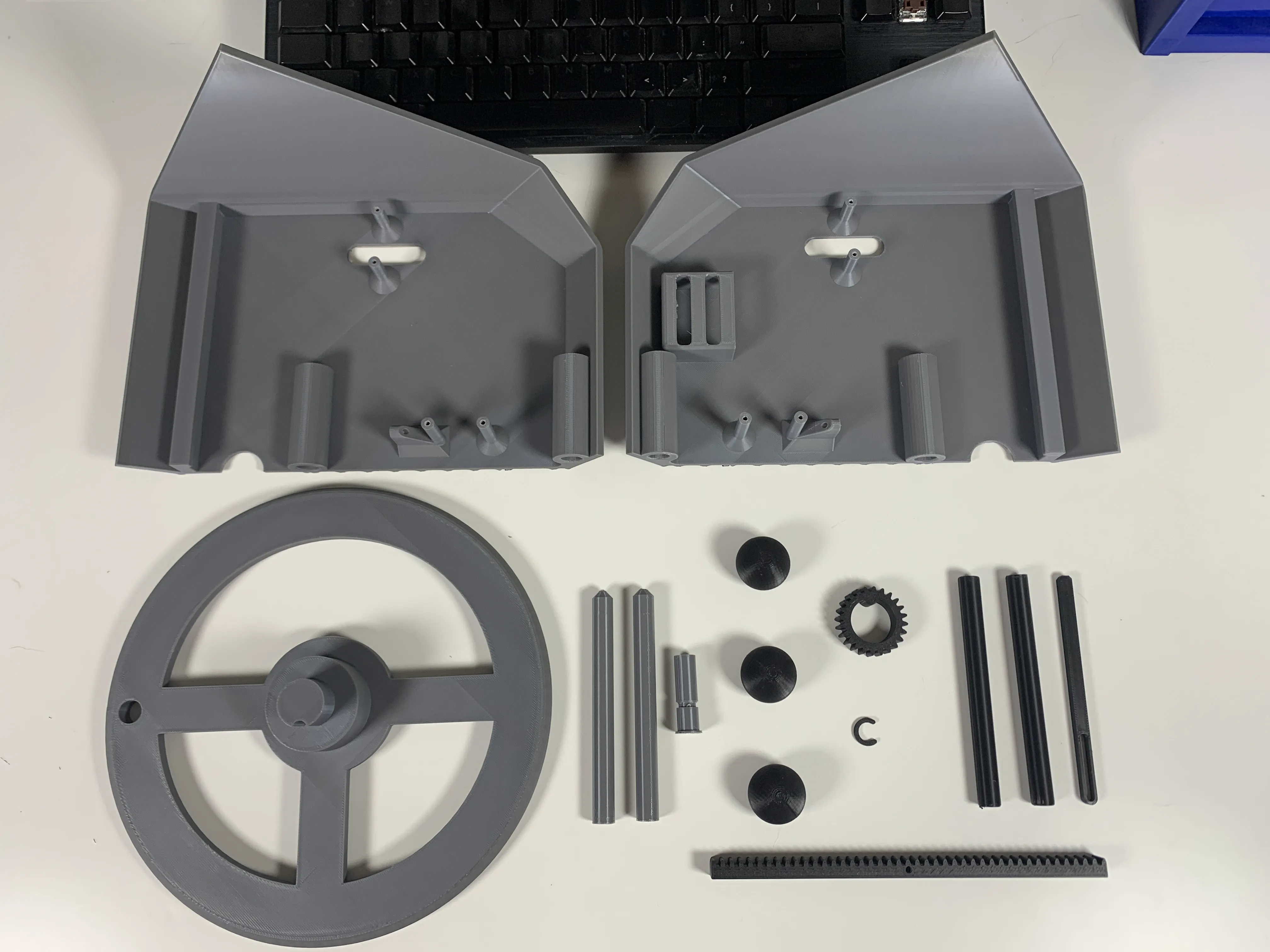
Non-Printed Parts
You should have:
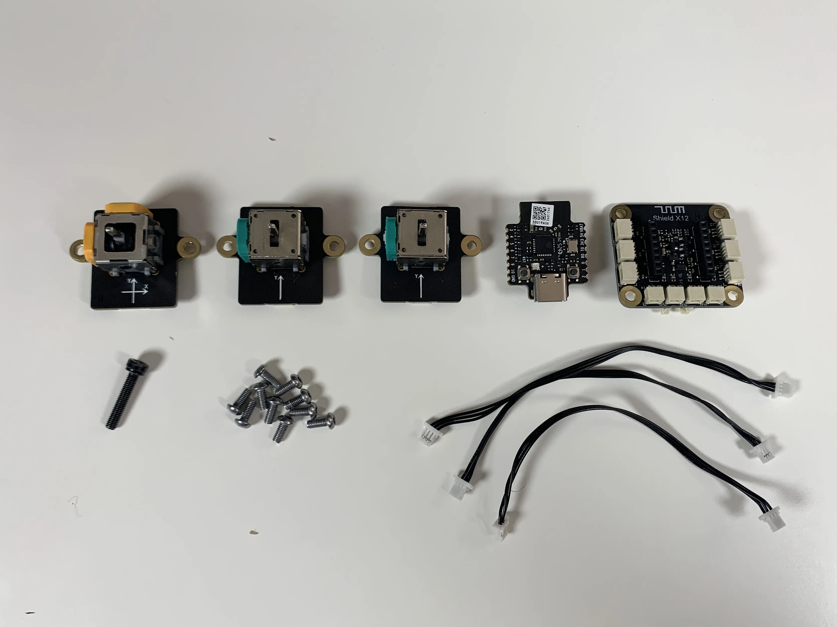
- 10× M2.5 screws
- 1× M3 screw
- 3× 3-prong cable
- 2× single-axis joysticks
- 1× dual-axis joystick
- 1× transmitter shield
- 1× multi-function core
1× AAA battery case
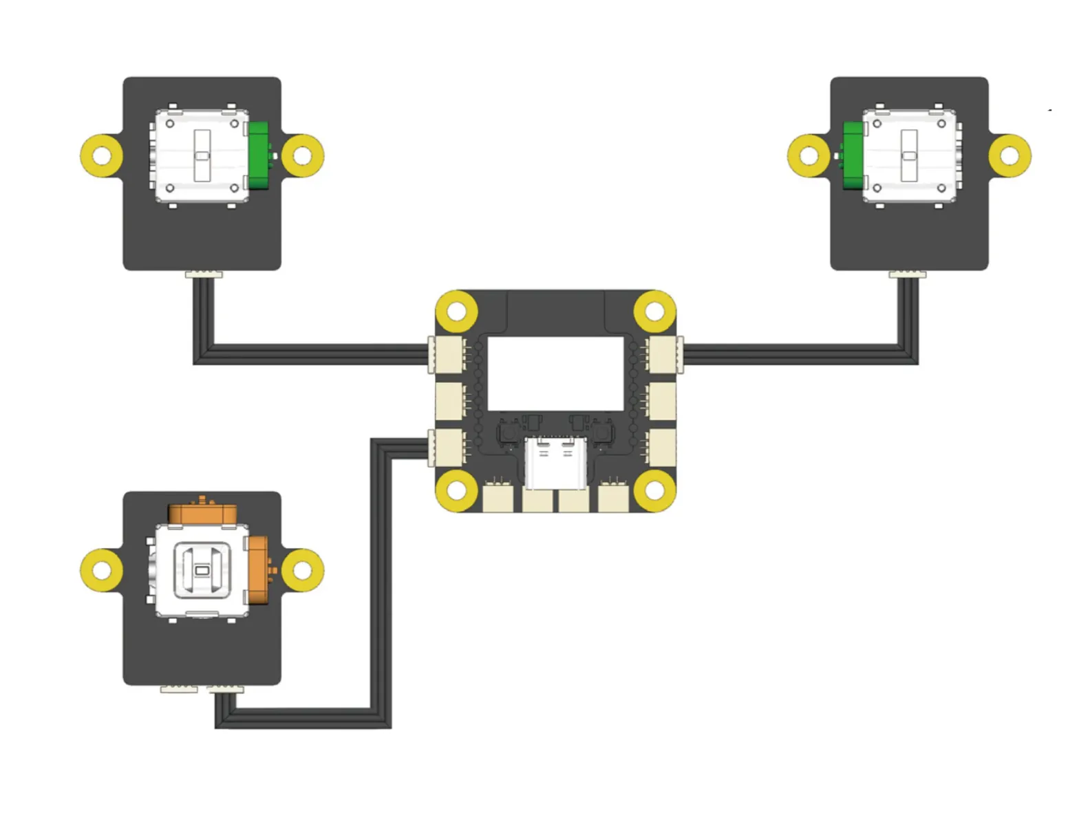
Wiring Diagram
Assembly Steps
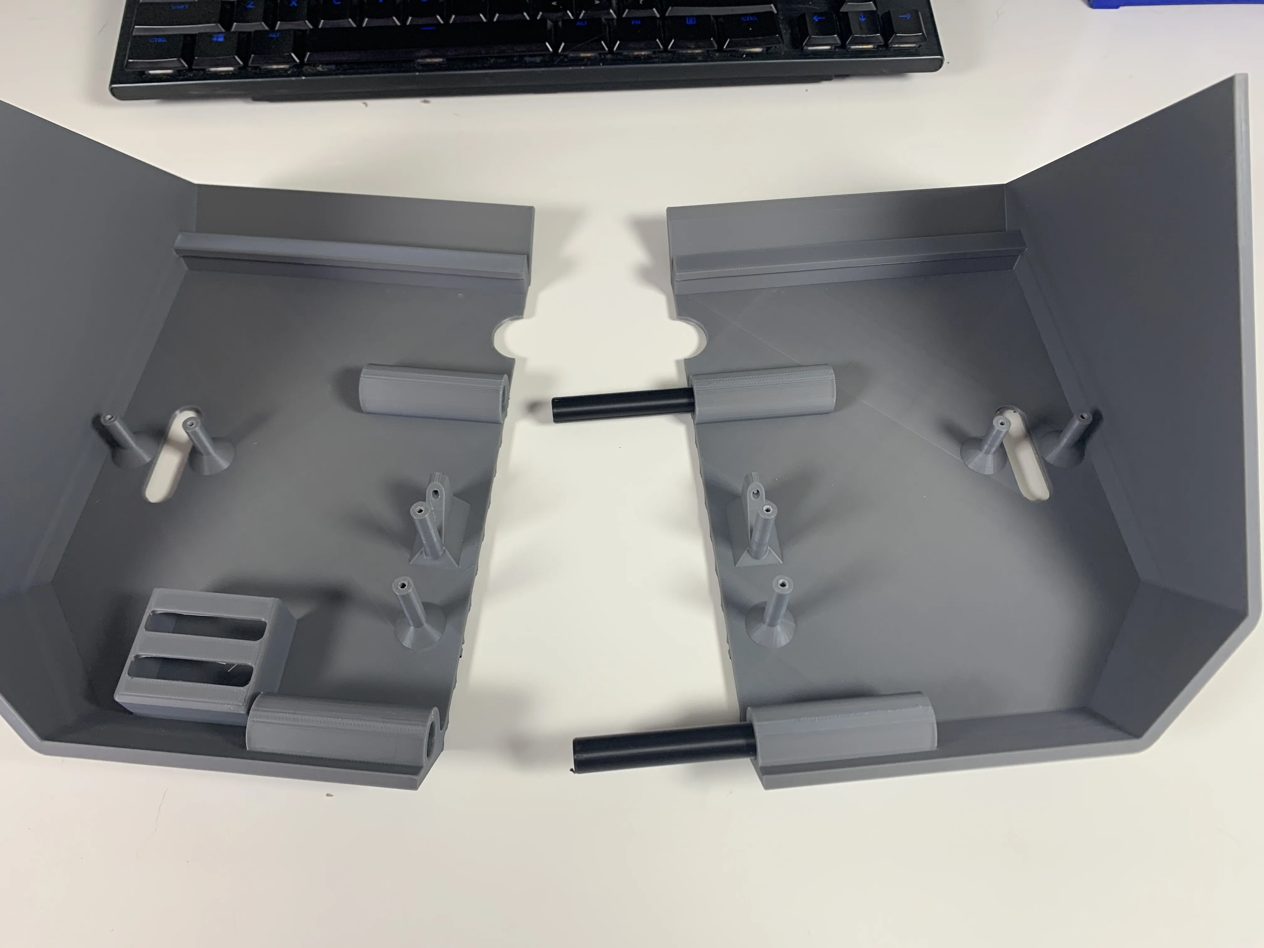
Step 1 – Connect Main Bodies
- Connect the two main body pieces using the two pegs.
Ensure they are fully aligned and securely connected.
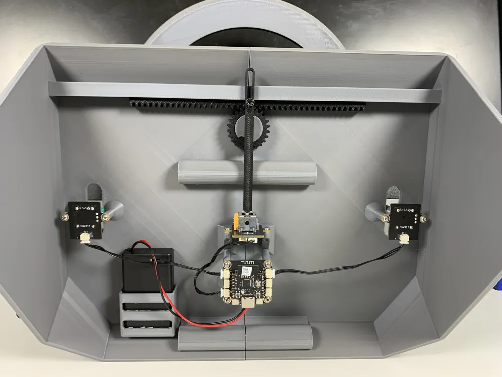
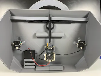
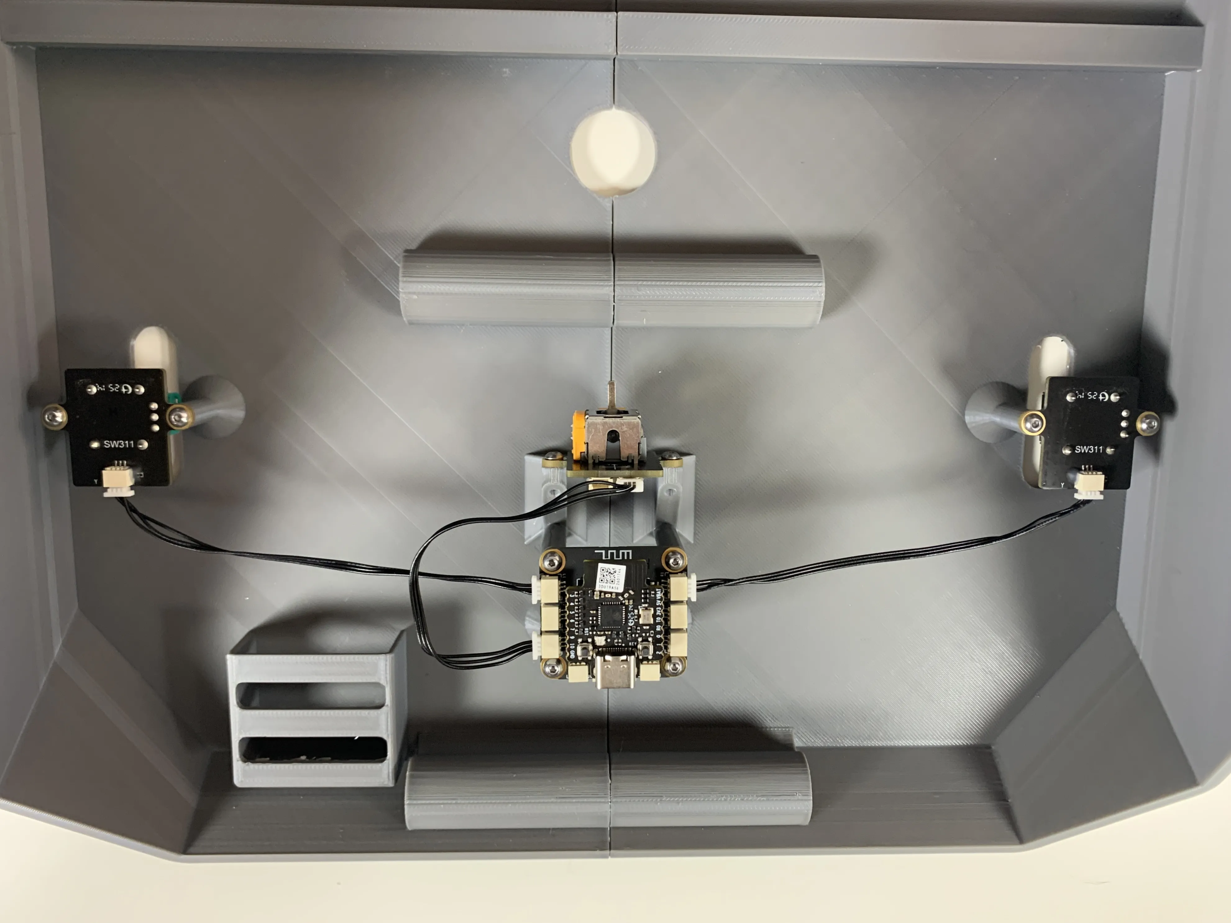
Step 2 – Install Electronics
- Attach the electronics using the 10 M2.5 screws.
Ensure all components are oriented correctly as shown in the photo.
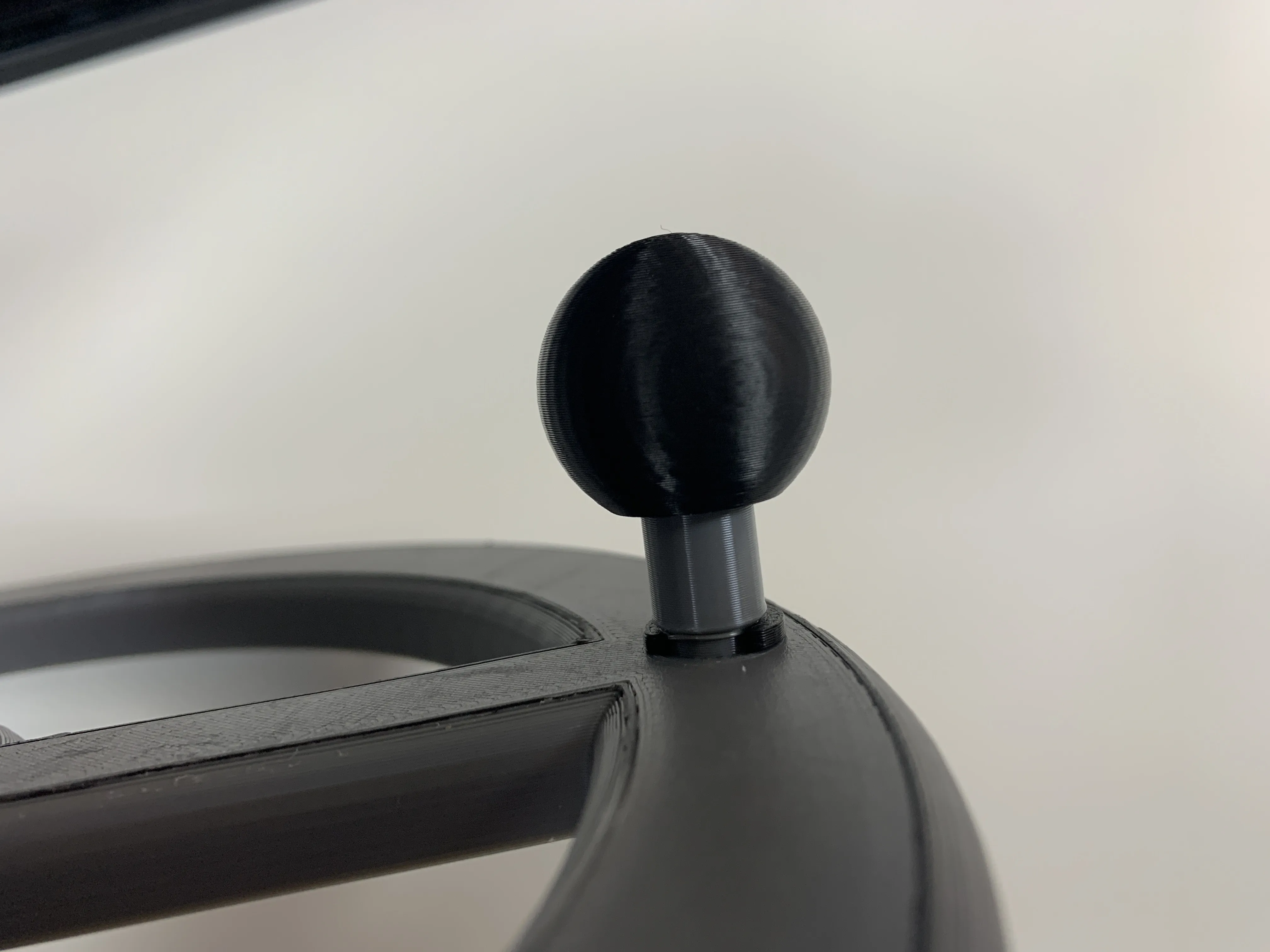
Step 3 – Attach Steering Wheel
- Slide the pin through the steering wheel.
- Secure it with the C-clip.
Add the knob to complete the assembly.

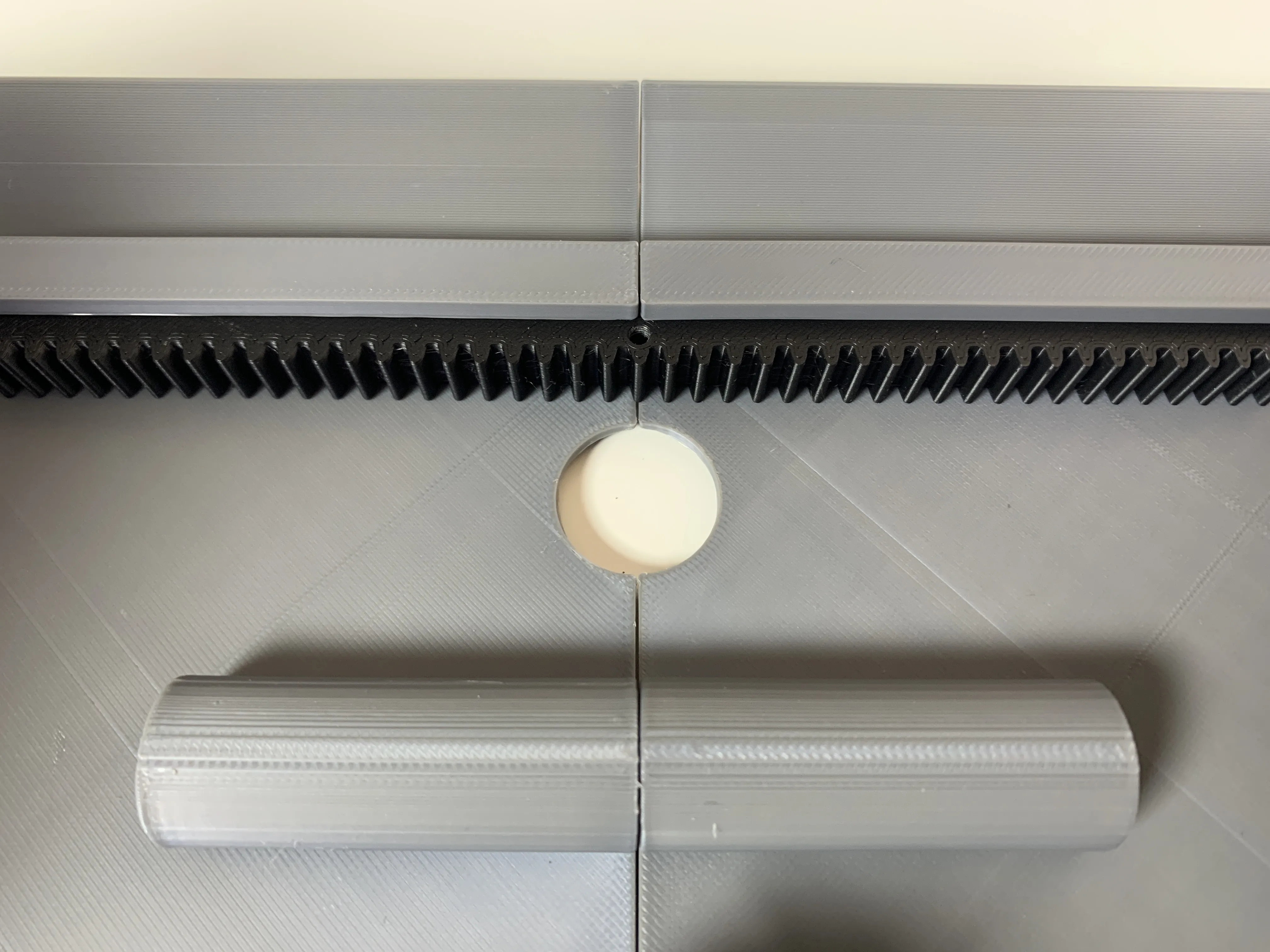
Step 4 – Insert Rack
- Slide the rack into its holder.
If it does not fit smoothly, double-check that all supports are removed from the printed parts.
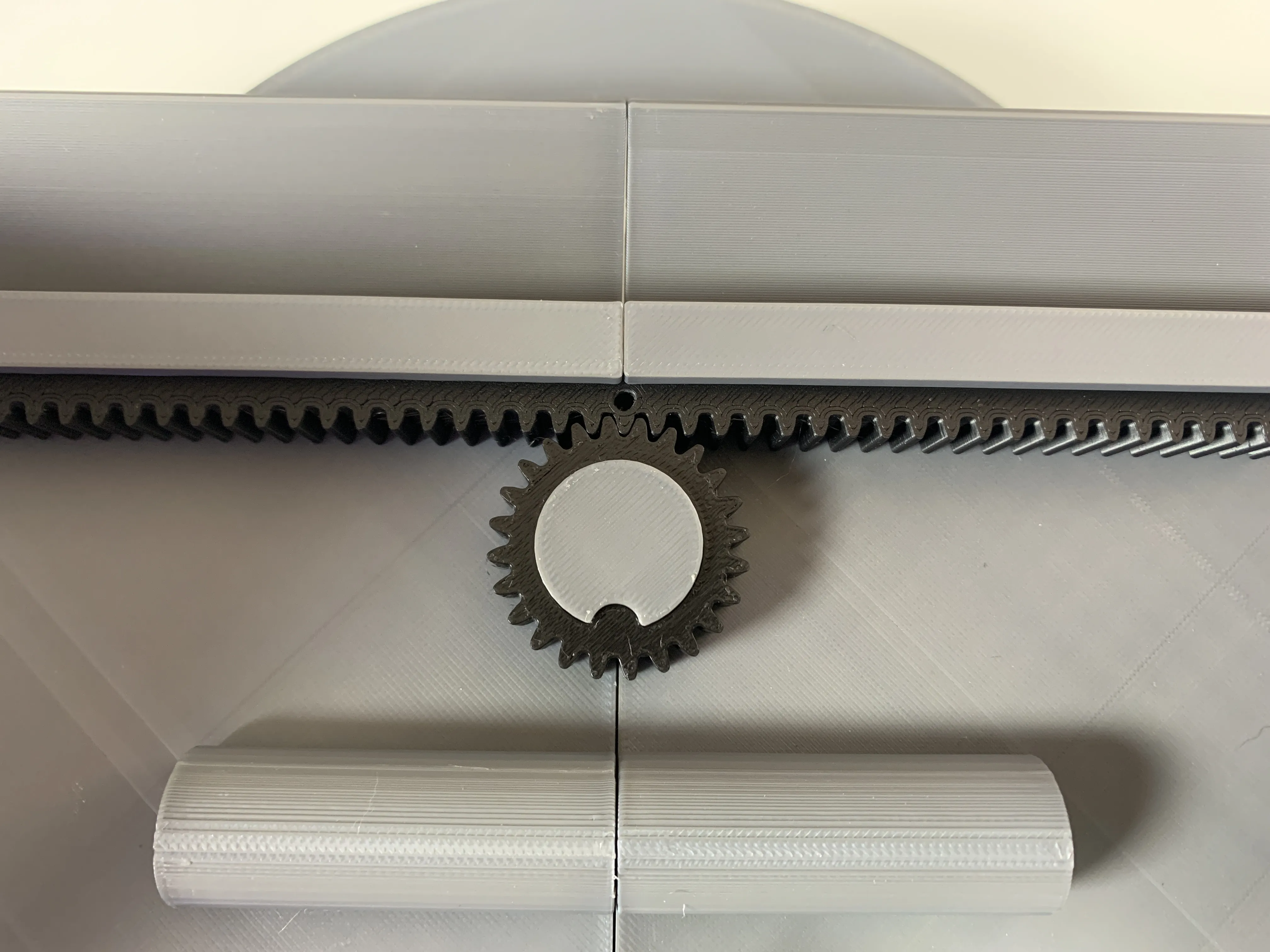
Step 5 – Install Gear
- Press the gear up against the rack, with the tab facing downward.
- While holding the gear, push the steering wheel all the way through.
Some glue may be needed to secure it firmly.
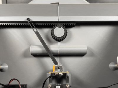
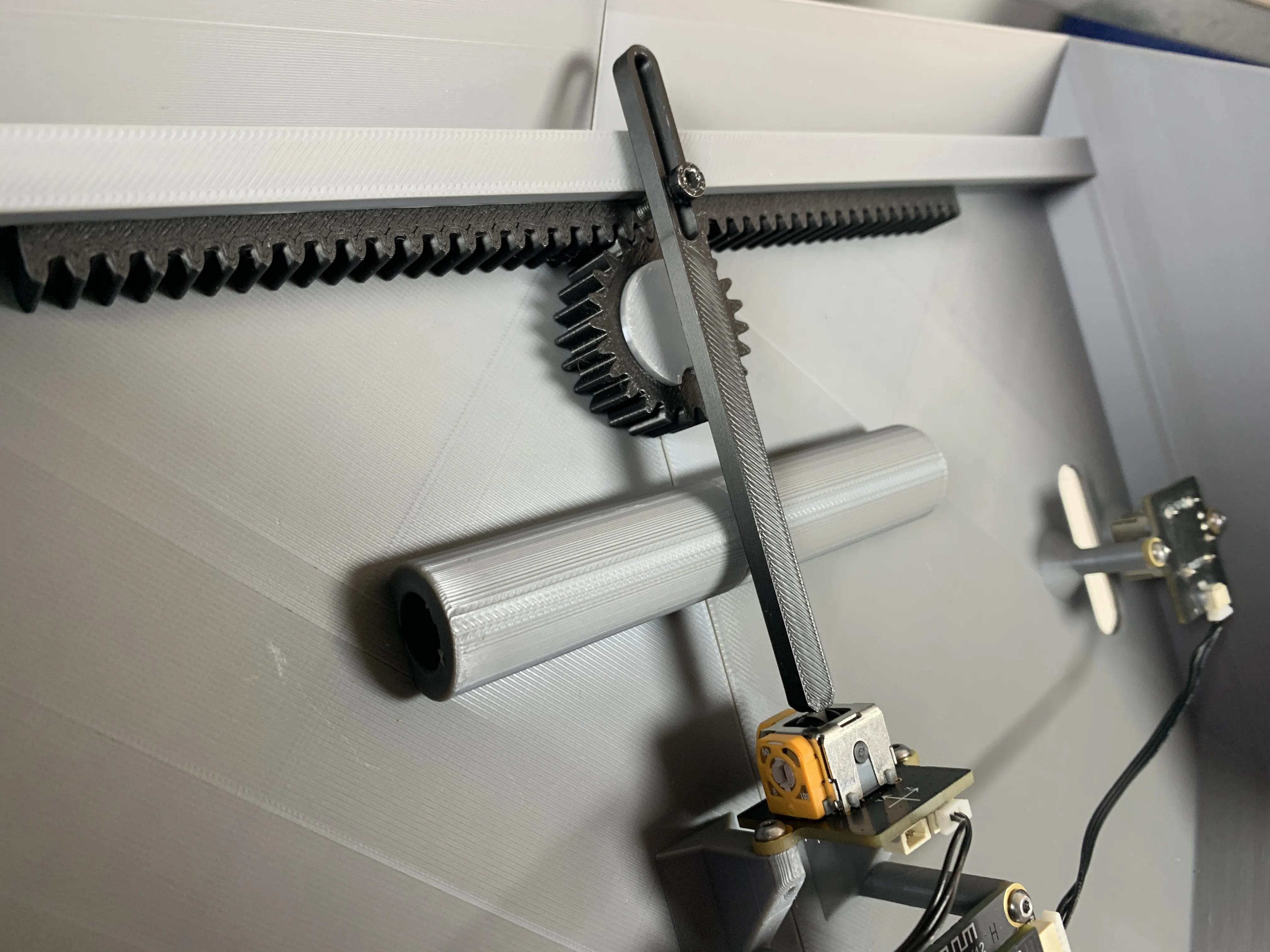
Step 6 – Attach Bar to 2-Axis Joystick
- Slide the long bar (with the slit on top) onto the dual-axis joystick.
- Screw the M3 screw into the rack, making sure it passes through the slot.
Leave enough room for the bar to slide freely.
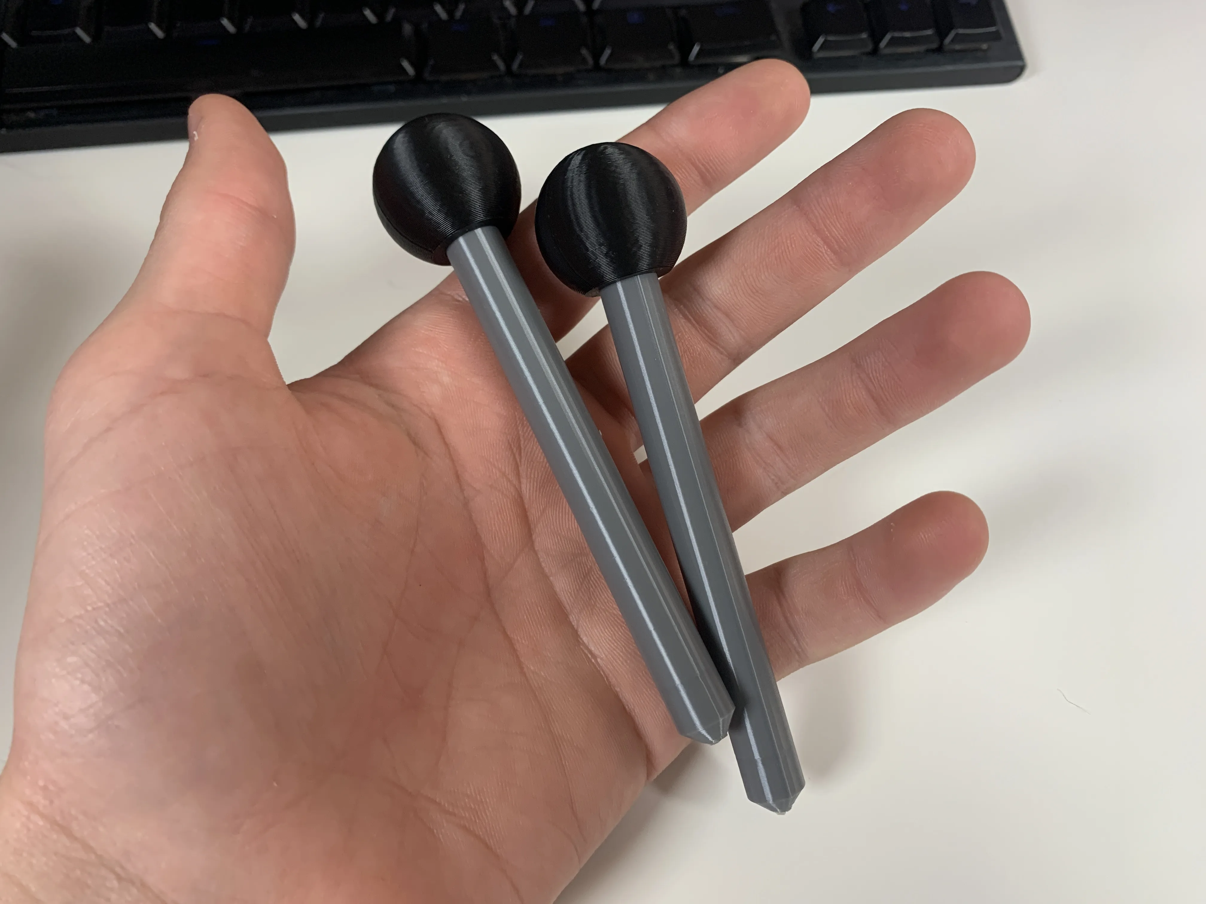
Step 7 – Attach Levers and Knobs
- Slide the two knobs onto both levers, ensuring they are fully seated.
Flip the controller over and push both levers all the way onto the single-axis joysticks.
Membership
If you’d like to support me, consider joining my Support Tier Membership! For just $3 a month, you’ll be making a huge impact on my work. Your contributions help me keep creating, improving, and innovating! 😁
No AI is used in this model. All of my models are made by me in Fusion 360.
Documentation (1)

License

You shall not share, sub-license, sell, rent, host, transfer, or distribute in any way the digital or 3D printed versions of this object, nor any other derivative work of this object in its digital or physical format (including - but not limited to - remixes of this object, and hosting on other digital platforms). The objects may not be used without permission in any way whatsoever in which you charge money, or collect fees.


Comment & Rating (39)