Small manual turntable like a sushi conveyor belt: utilizing space under shelves


Print Profile(1)

Description
Addendum
At the end of this description, I have added instructions on how to freely change the length of the parts. Please see this if you need longer parts
Overview
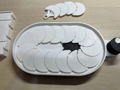
I created a small manual turntable inspired by conveyor belt sushi
The minimum footprint size is 300mm x 155mm
It can also be extended in 30mm increments using extension parts
This turntable is intended for use in narrow spaces with depth, such as under shelves, to make items at the back more accessible
You could also place small plates or sushi on it and play sushi chef
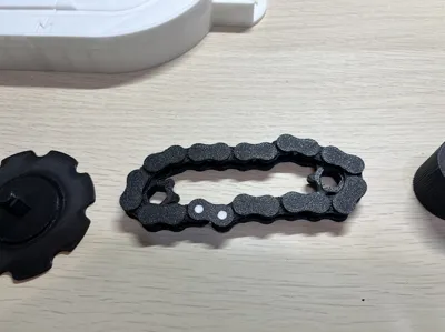
Since it is designed to be placed under shelves, the knob for rotating the tray (belt conveyor) needed to be placed outside the tray. Also, to quickly retrieve items from the back of the shelf, I wanted the tray to move quickly without having to turn the knob many times. By creating a mechanism where a chain transmits the rotation of the knob to the gears inside the turntable, these two requirements were met
I used an already published chain for this mechanism (https://makerworld.com/models/1523122). Thank you
22 chain links are used. Do not use the original connectors published at the URL above. To ensure the chain connectors fit inside the turntable, please use the connectors on my plate
After assembly, a part of the chain is exposed and visible under the hand-rotated knob. This is because a space was needed to insert the chain during assembly of the turntable and also because the model needed to be scaled down to fit within the A1 mini build plate
Assembly Instructions
- Assemble the chain. Use my model for the chain connectors to ensure the chain thickness does not change at the connector sections
- Insert two small chain rings inside the chain
- With the chain and chain rings combined, place them into the turntable's mainbody
- Position the shaft of the large gear, which rotates the tray at the center of the turntable, so that it passes through the chain rings and its tip fits into the small hole in the mainbody. This will prevent the chain from coming out
- Next, for the hand-rotated knob, ensure its shaft also passes through the chain rings and fits into the small hole at the bottom of the body
- At this point, rotate the knob to confirm that the large gear rotates
- If the gear rotation is fine, arrange the trays on top of the main body, and assembly is complete
Chain Assembly Instructions
Print a chain with a link length of 12.7mm from the URL above or similar sources. A total of 22 links are required
The chain will have a lot of support material immediately after printing, so you will need to remove it as shown in the enlarged photos.


Insert the white connector with two pins from the bottom side of the chain, and secure it with the holed connector from the top


Install the assembly into the main body with the white connector facing downwards

Important Notes
Although the length of one chain link is 12.7mm, the finished chain has some play (dimensional tolerance), so the distance between the two chain rings is a few millimeters longer than the theoretical length, taking into account measurement results from prototypes. However, depending on the filament actually used, it may be necessary to adjust the spacing between the chain rings
Enable supports when printing the turntable's mainbody and trays
I printed with PETG
Addendum
Since this model was also submitted to a contest, I wanted all parts to be 3D printable, so a 3D printed chain is used to transmit power to the turntable
Therefore, the thickness of the turntable body was determined to accommodate the chain. It is a bit thick, but the larger opening made it easier to remove print supports
After publishing this model, I learned that there are creators on MakerWorld who have published timing belts and timing pulleys. Timing belts require flexibility, so TPU filament is reportedly used, but I have no experience printing with TPU yet. If those timing belts were used, my model might have been made thinner
How to create extension parts of your desired length in Bambu Studio
As you may need longer extension parts, I will show you how to create extension parts of any desired length using the standard editing functions of Bambu Studio
Writing all the steps makes it long, but it's simple and can be done in about a minute once you get used to it. Please use it as a reference
- Download and open the 3mf file
- Click and select Extrabody on Plate3
- Since you don't want to change the dimensions of the connector parts at both ends of the object, detach the connector parts at both ends before adjusting dimensions. Cut twice to split the object into three parts
- Select <Cut> from the top menu bar
- A rotation knob for the cutting plane will appear; rotate the green knob by 90 degrees to make the cutting plane vertical
Enter [-10] in <Movement> within the <Cut> menu to shift the cutting plane to the left. The value of Movement can be anything as long as the cutting plane does not overlap with the connectors at both ends of the object


- Check <Cut to parts> and click the <Perform cut> button
- If you display Objects in the left Sidebar, it should be split into Extrabody_A and Extrabody_B
- Select Extrabody on Plate3 again. After cutting in Step 8, it is already selected. Not the detached _A or _B
- Select <Cut> from the top menu bar again
- A rotation knob for the cutting plane will appear; rotate the green knob by 90 degrees to make the cutting plane vertical
Enter [10] in <Movement> within the <Cut> menu to shift the cutting plane to the right. The value of Movement can be anything as long as the cutting plane does not overlap with the connectors at both ends of the object

- Check <Cut to parts> and click the <Perform cut> button
- The object is now split into three parts. When extending the part, move the connectors to their correct positions
- Select the left part from the Sidebar and click the <Move> button in the top menu bar
In the numerical field for the X direction, enter the value with the desired dimension added. For example, if it contains [-20] and you want to increase the extension part by 60mm, enter [-80] to move it 60mm to the left. The size to extend the part should be a multiple of 30mm


- Select the middle part in the Sidebar and click the <Move> button in the top menu bar to move it to the approximate center of the end parts. This movement does not need to be precise
- Select the middle part and choose <Scale> from the top menu bar
- Uncheck <uniform scale>
Drag the red points on the part to extend it. Extend it until it overlaps with the connectors at both ends. It doesn't need to be perfectly aligned; just ensure there are no gaps when overlapping


Select all three parts in the Sidebar, right-click, choose <Merge into Single Part>, and combine them into one part

The merged object still shows overlapping lines, so remove them. Right-click the merged Object in the Sidebar and click <Fix model>

- Done. Check the dimensions. In this example, an object that was 60mm long was extended by another 60mm, making it 120mm long. After that, slice it and confirm that there are no issues
License
You shall not share, sub-license, sell, rent, host, transfer, or distribute in any way the digital or 3D printed versions of this object, nor any other derivative work of this object in its digital or physical format (including - but not limited to - remixes of this object, and hosting on other digital platforms). The objects may not be used without permission in any way whatsoever in which you charge money, or collect fees.
Comment & Rating (23)