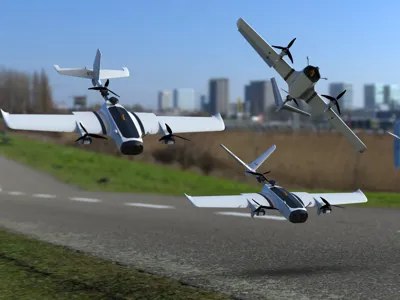
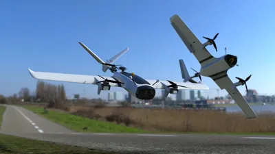
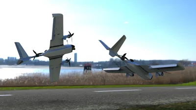
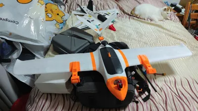
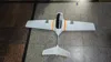
V120 Scout Y3 Layout V-Tail VTOL Fixed-Wing


Print Profile(1)
Description
I have divided the slicing files into two parts: the wings and fuselage made of foaming filament, and structural parts made of non-foaming filament. For foaming material, it is only recommended to use Polyhyper Foaming PETG LW.
It is recommended to use OrcaSlicer to slice the 3mf files from all CAD/STL files, as Bambu Lab currently does not support the 2DLattice infill type.
Carbon tube, one piece, 1 cm in diameter and 1 meter long.
Carbon rod, 3 mm in diameter, about two 1-meter long pieces are needed. For 2 mm thick carbon rods, one 1-meter long piece is generally enough, but it is recommended to prepare two.
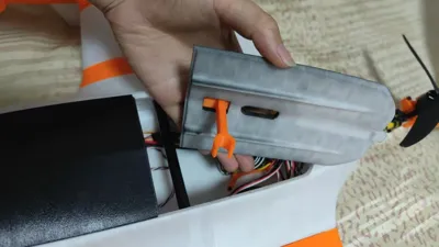
The tail boom uses a 15mm wide square tube. The recommended length is 25 to 30 cm, with a wall thickness of 1 mm. Aluminum alloy can be used for a low-cost option, or carbon fiber if budget is not an issue. I have reserved a 0.3 mm tolerance for the inner hole of the model, but if foaming filament is used, an interference fit might still occur, making it quite tight. If it doesn't fit, it's recommended to prepare some 200-grit sanding blocks to process the tube, or consider heating it.
Spring steel wire servo pushrod is recommended to be 1mm+. Four quick-adjust connectors are needed.
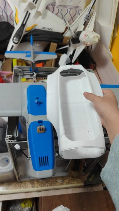
The nose requires two M3 heat-set inserts and screws for fastening. The screw length is recommended not to exceed 8 mm, but if foaming material is used, it is advisable to additionally secure the nuts with glue.
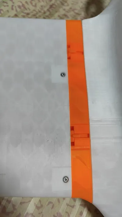
Each wing section is also secured with M3 heat-set inserts and 6 mm long screws. The holes on the sides of the tail also use M3 heat-set inserts, and M3 screws are used to secure the tail boom.
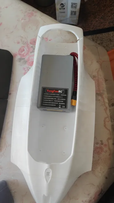
The 3mm holes on the rear fuselage, the bottom of the flight controller mounting position, and the battery mounting plate are for adding M2 heat-set inserts.
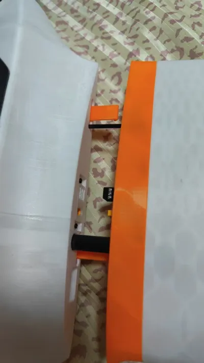
Between fuselage sections, it is recommended to use organic solvents like acrylic glue; the bond will be very strong. If you see a 2mm hole in the cross-section, insert a 2mm carbon rod for alignment.
I originally intended to divide the ailerons into two sections, but they were too tall and prone to tipping, so I directly used slicing software to divide them into 4 sections. This might be slightly different from the assembly demonstration model I will make later.
In terms of electronics
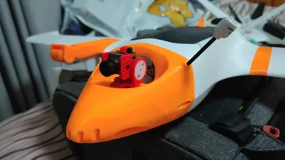
Servos used are PTK7452, and tilt servos use 7465. You can also use 7465 for all.
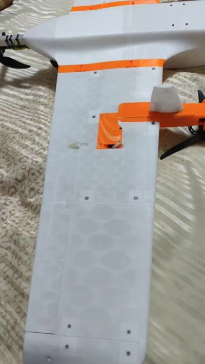
Motor used is 2810 900KV. ESC used is 80A AM32, but 45A is actually enough. Any motor with a 4-hole, 16*16 or 19*19 mounting pattern can be installed.
Flight controller used is SpeedyBee F405 Wing.
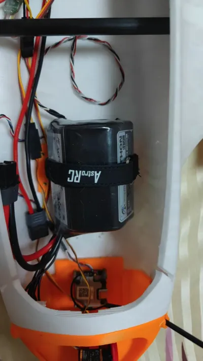
The battery is maximally compatible with 6S3P, but it is recommended to use 6S1P or 2P.
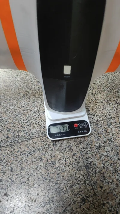
Takeoff weight is not recommended to exceed 2.5kg; the ideal takeoff weight is around 1.5kg.
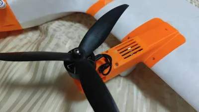
This aircraft was initially intended to be a 3D printed version of the ZMO, but considering the differences in materials and processes, it was not fully replicated. In the end, it was completely designed as a brand-new aircraft. Compared to the ZMO, it has a larger wing area, and both the tail and main wing sizes have been enlarged. The canopy opening and closing method also adopted my consistent carbon tube clamping method since the T116, which is both secure and and convenient. The quick-release wing structure uses a double-button buckle design; assembly and disassembly only require a simple press, eliminating the hassle of screwing. This time, following the advice of fellow modelers, the control surfaces use a pivot structure, no longer requiring TPU hinges. The ailerons use a 3mm carbon rod as the axis, and the tail uses a 2mm carbon rod. The carbon rod axis also serves to strengthen the wings. One point to note is that the carbon rod of the main wing, as shown in the figure, only needs a small section protruding, serving merely as a positioning aid.
For this model, I have uploaded the tilt arm and nose template STP files in all CAD files to facilitate DIY by everyone, adapting to more accessories and electronics.
I will test and upload the flight controller configuration file soon.
Currently, flight tests have been conducted under a multi-rotor configuration, with a hovering current of 20A.
Documentation (2)
License
You shall not share, sub-license, sell, rent, host, transfer, or distribute in any way the digital or 3D printed versions of this object, nor any other derivative work of this object in its digital or physical format (including - but not limited to - remixes of this object, and hosting on other digital platforms). The objects may not be used without permission in any way whatsoever in which you charge money, or collect fees.
Comment & Rating (9)