
Slayer exciter Tesla coil (around 5kV)
Print Profile(1)
Description
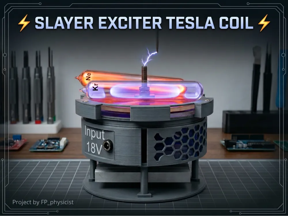
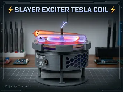
⚡Slayer Exciter Tesla Coil⚡
Introduction
- The Slayer Exciter is a simple type of Tesla coil that generates high-voltage, low-current electricity using a self-oscillating circuit, and it’s incredibly minimalistic—requiring only five main components!
- I built a Slayer Exciter Tesla Coil using two MJE3055T transistors in parallel to handle the current. I also added a blue LED with a 5.6 kΩ resistor as a simple visual indicator.
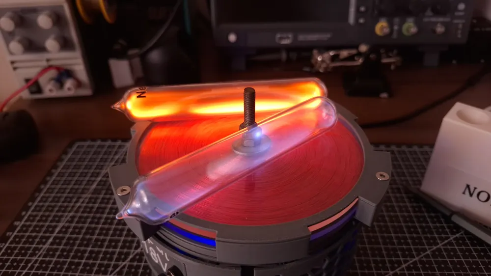
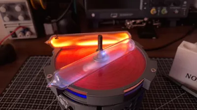
- It’s a compact setup that demonstrates high-voltage resonance in a safe, low-power format. The coil produces impressive sparks for its size, and the blue LED adds a nice touch when the circuit is active.
- In my setup the primary coil is placed below the secondary coil. This model was hugely inspired by Plasma Channel's Slayer exciter pancake coil.
How does it work?
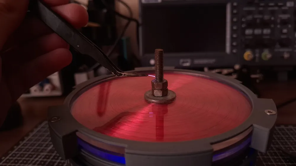
- It works by feeding a primary coil with pulses from a transistor, which induces a high-frequency current in the secondary coil. This causes the voltage in the secondary to rise dramatically, producing sparks and corona discharges at the top. Essentially, it’s a resonant transformer that converts low-voltage DC into visually striking high-voltage AC without needing a separate oscillator.
Boost Me (for free)
Want to build more cool physics stuff? Boost me and I will bring it closer to you :)
How to built one yourself!
Step 1 - ordering parts
- 1x Wire for secondary, I used 0.2mm red copper wire (https://www.aliexpress.com/item/4001017426787.html?spm=a2g0o.order_list.order_list_main.42.57861802qz0ou3)
- 1x Wire for primary, I used 0.32mm copper wire (https://www.aliexpress.com/item/1005006500055371.html?spm=a2g0o.order_list.order_list_main.82.57861802qz0ou3)
- 1x 5.6kΩ resistor
- 1x Blue LED
- 2x MJE3055T NPN bipolar transistors (buy them in bulk!) (https://www.aliexpress.com/item/1005007570287101.html?spm=a2g0o.order_list.order_list_main.122.57861802qz0ou3)
- 2x Acrylic plates, I used 120mm(1Pc), 4mm (https://www.aliexpress.com/item/1005008057427366.html?spm=a2g0o.order_list.order_list_main.132.57861802qz0ou3)
- 3x Brass threaded inserts (also buy a bulk, they come in handy), I bought Length 4mm, M3 (OD4.2mm) 50pcs (https://www.aliexpress.com/item/1005007342105110.html?spm=a2g0o.order_list.order_list_main.147.57861802qz0ou3)
- 3x M3x10mm screws
- 1x M6x35 screw, 2x nut, 1x washer
- 32x neodymium magnet (5x2mm) (https://www.aliexpress.com/item/1005001832523652.html?spm=a2g0o.order_list.order_list_main.10.638b1802fTLh5o)
- Spare prototype board
- I also recommend 4x KF301-3P 5.08mm 3 Pin Screw Terminal for connections
- 1x pair DC power jack (https://www.aliexpress.com/item/1005002755217001.html?spm=a2g0o.order_list.order_list_main.32.61711802KFTkCE)
- Some spare wires
- Soldering iron
- Super glue
Step 2 - building it
After gathering all parts listed above, we can start building it!
- First I would measure and edit the file called D1_customize_for_your_heatsink.stl so that the heat sink can sit on the 3D-printed part without issues (if you really want, you can glue it together using hot glue).
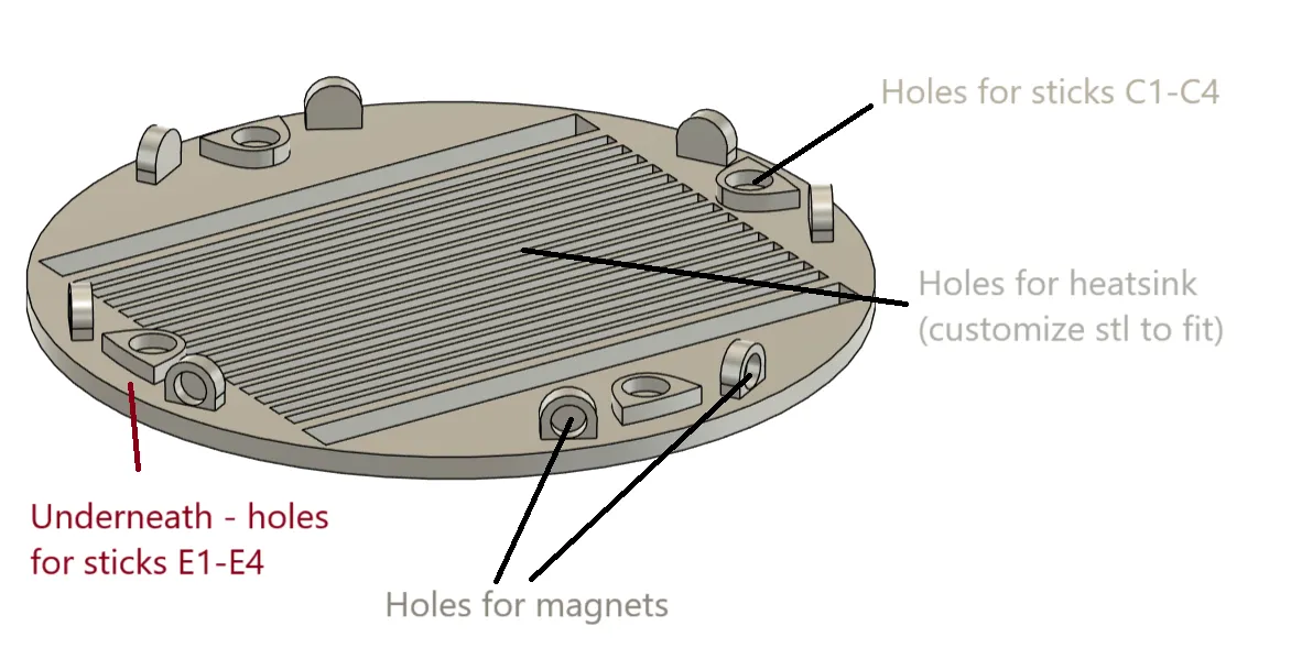
- If you have a different sized heat sink, it's possible that you might need to modify the E1-E4 sticks, so that there is enough space in between plates.
- After measuring and editing these files (or using mine D1 and E1-E4 files) you can print all the parts as they are in attached 3mf file.
- All the parts then come together.
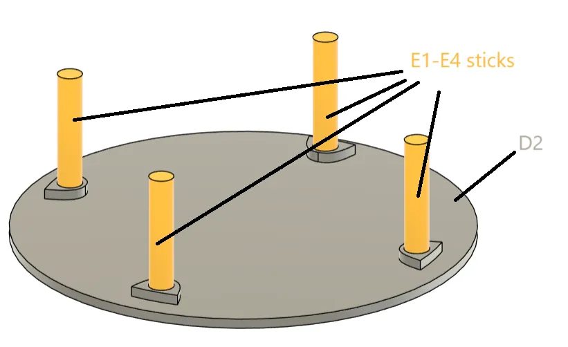
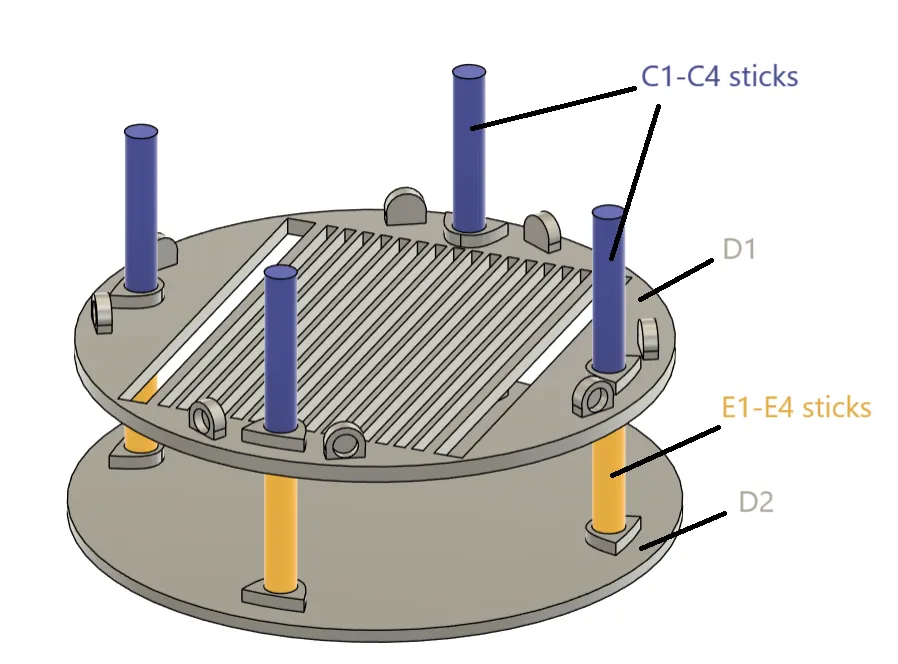
- Firstly super glue together parts named E1-E4 (sticks) to the bottom part D2. Then glue the sticks onto modified D1 plate. After that your casing should look like this:
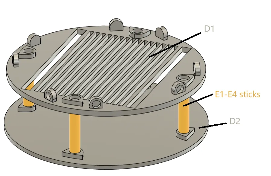
- Then place and super glue modified D1 plate on top of these sticks, so that it looks like schematic below:
- Then add C1-C4 sticks on top of the D1 plate:
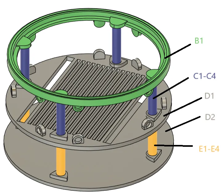
- Then glue B1 plate on the sticks C1-C4:
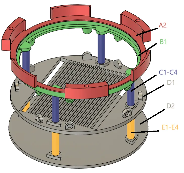
- Now glue A2 to B1
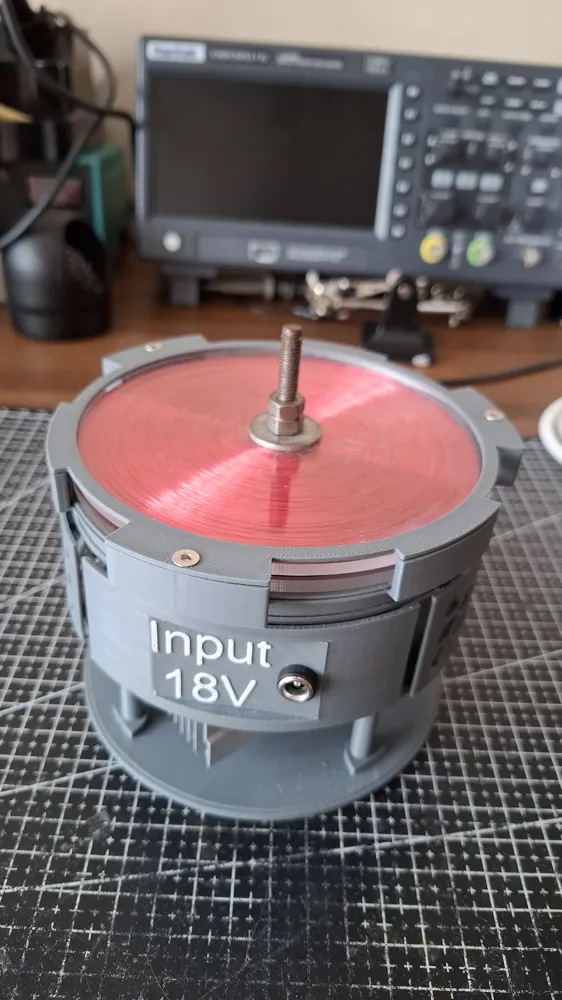
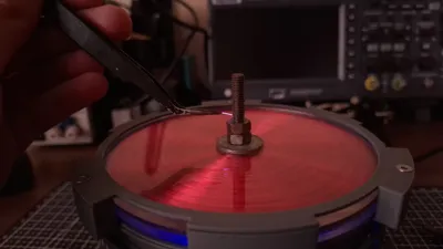
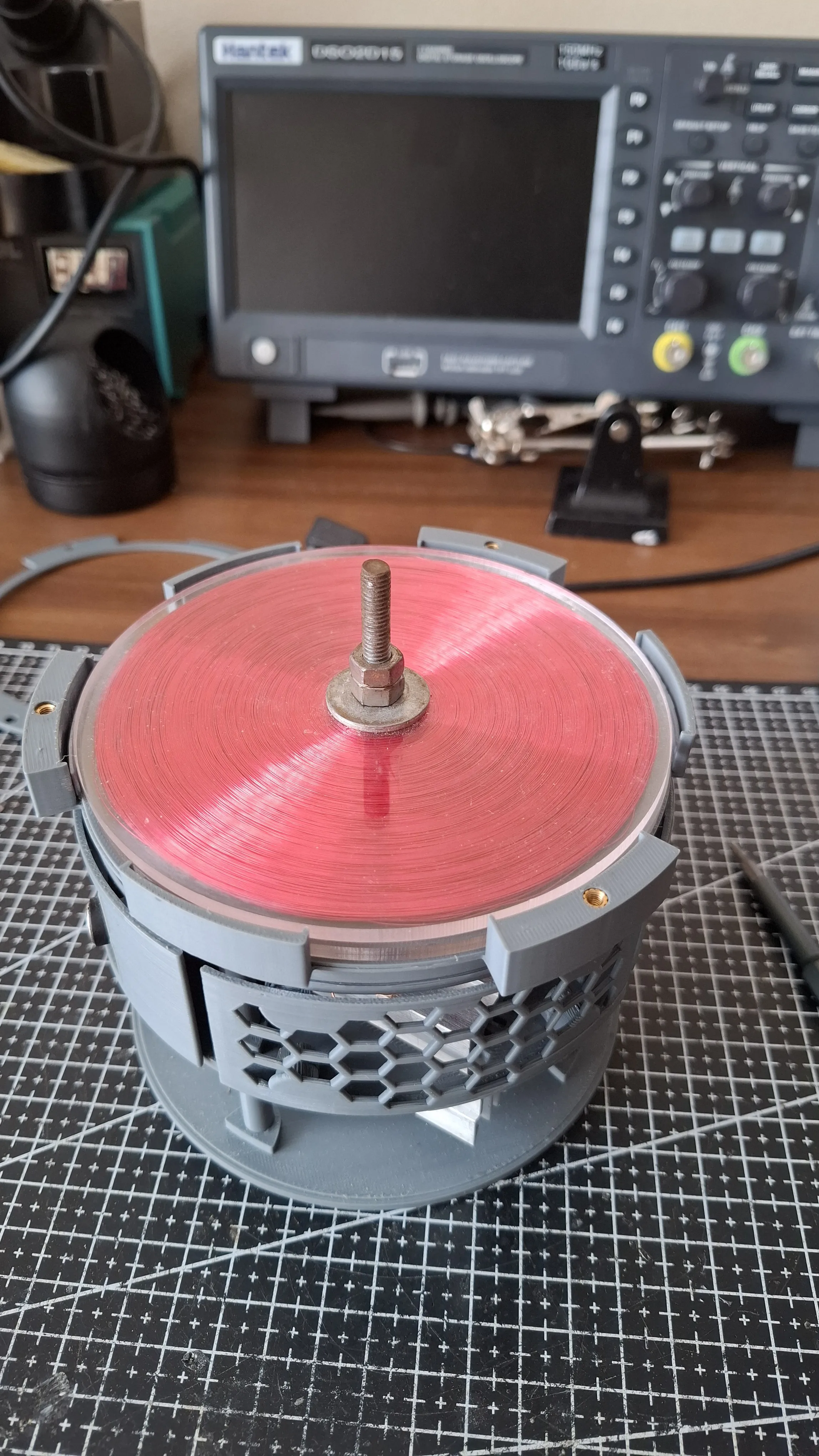
- Now we built the secondary coil. Start by carefully drilling M6 hole in the center of both acrylic plates (be sure to leave the covering plastic on it, so it doesn't get damaged), I would also recommend placing some wood underneath the acrylic plate, so it doesn't crack like mine did. After that you can put in the M6 screw and start winding the 0.2mm copper wire around the center, be sure to tighten the secondary properly, so it doesn't come of! For winding I used hand-drill. After reaching the end of acrylic plate, simply stop, tape the end of wire to the side and cut it (so there is some left-over), then you can create a small hole in the acrylic through which you can pull the wire through, so it won't come off on it's own.
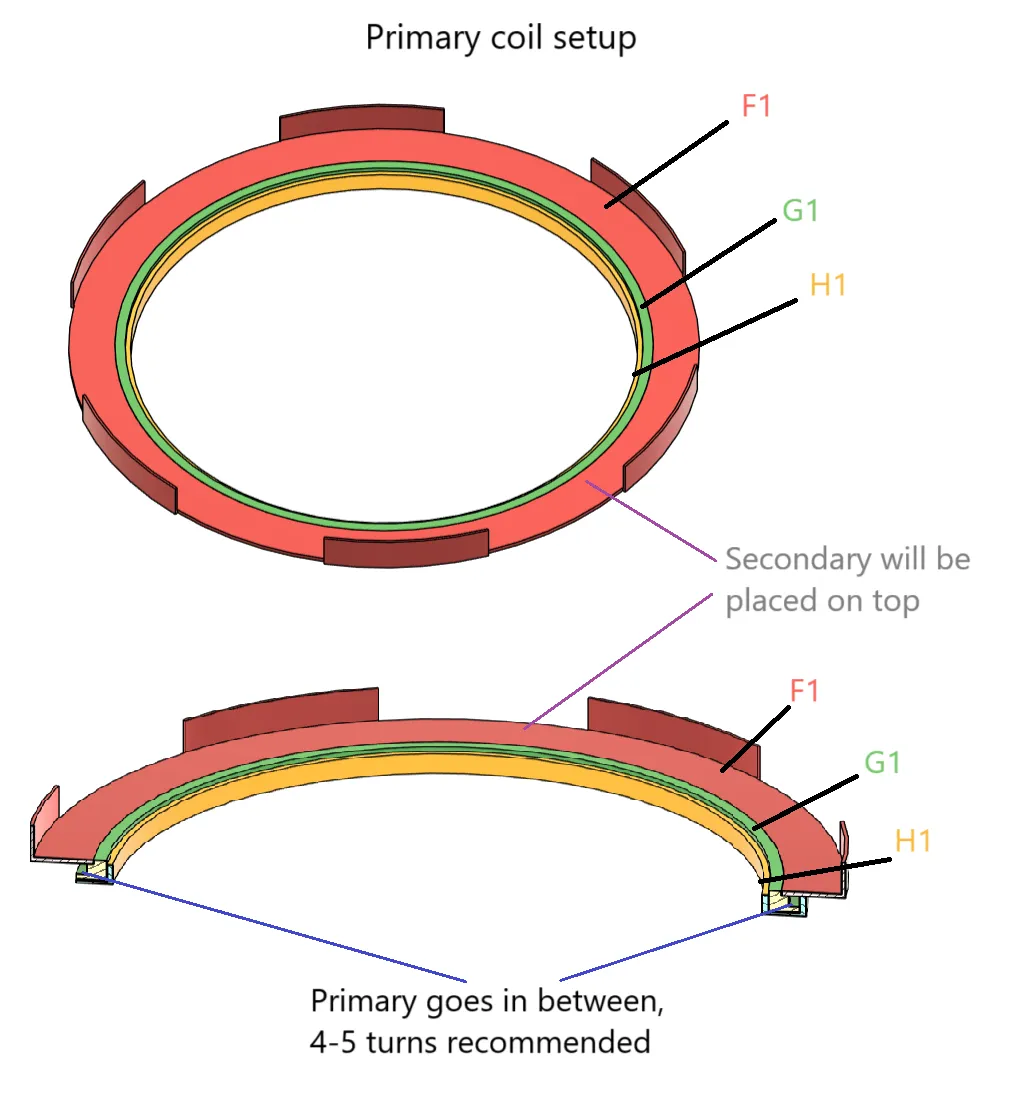
Next step is to make primary coil, for that you need to print out parts F1, G1, H1. Primary goes in between H1 and G1. Part named F1 is simply there to hold secondary coil and make the structure more stiffer, after assembly. For primary you will need a bit thicker wire than on secondary (I used 0.32mm). Wind around 4 turns (you can later test that out and add or lower number of turns based on the output) around G1 and after that simply shut it with H1 (if you want to make adjustments, don't glue it straight away!). Then place F1 on top of G1 as shown on the schematic below.
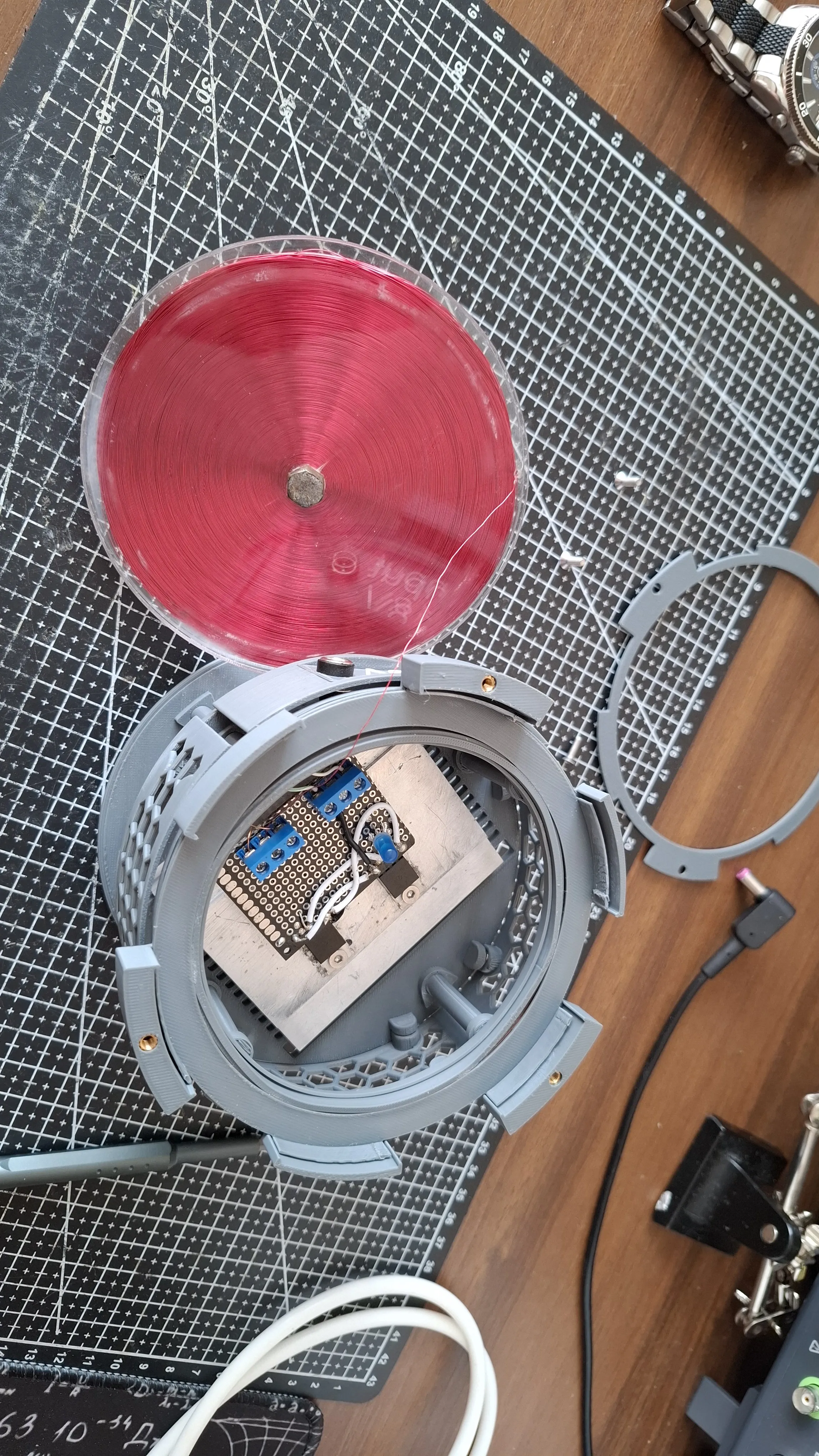
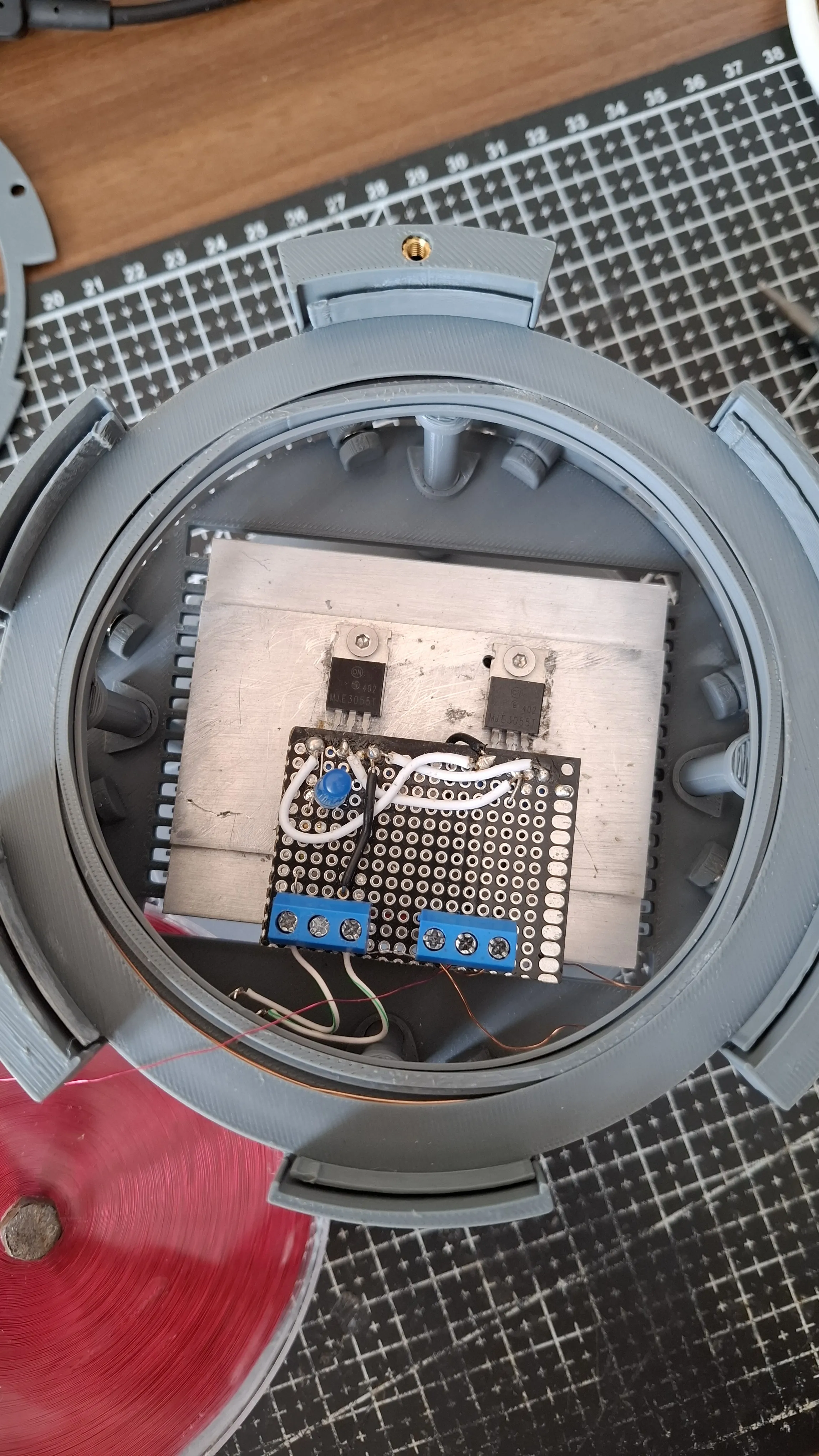
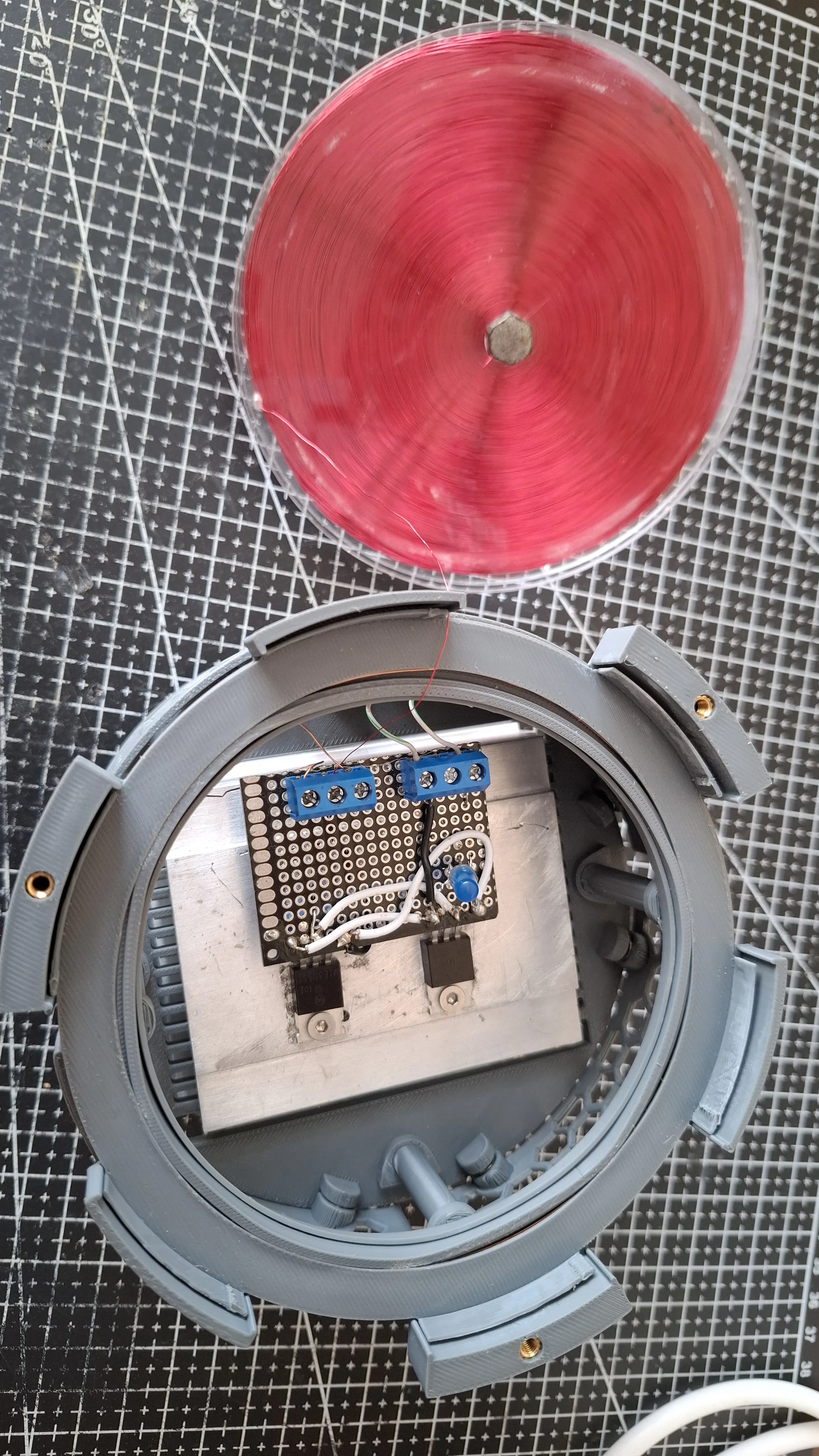
- Now we make the circuit for our Tesla coil. Simply take your prototype board and place the components as seen on schematic below, where I would recommend using terminal for MJE3055T, primary, secondary and input.
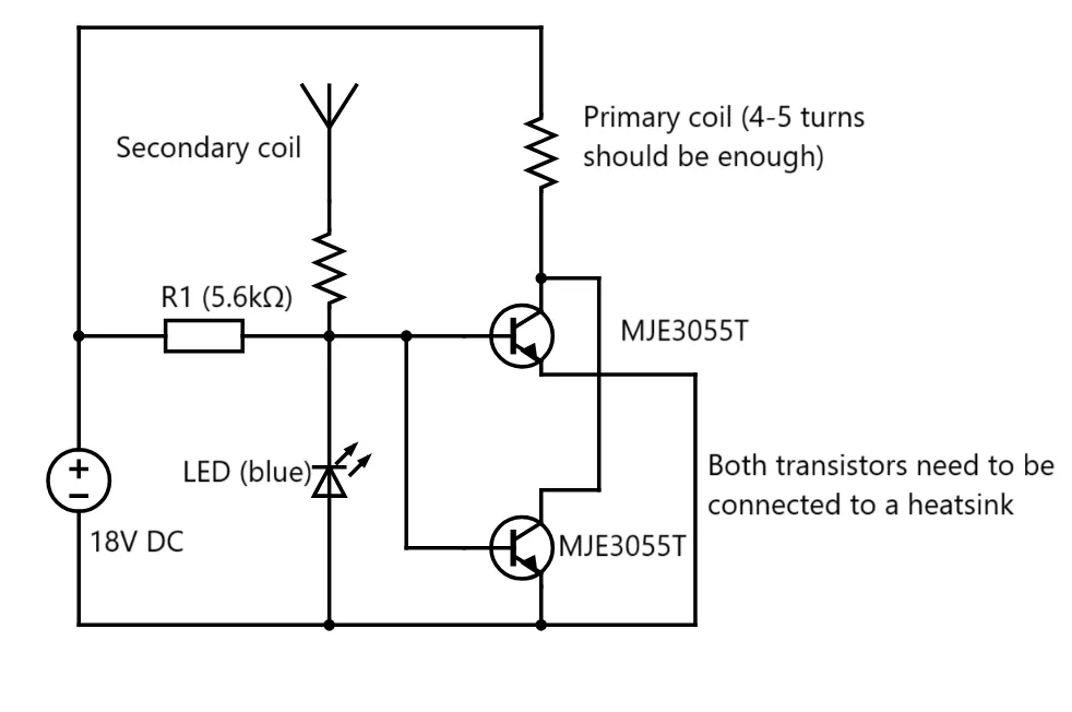
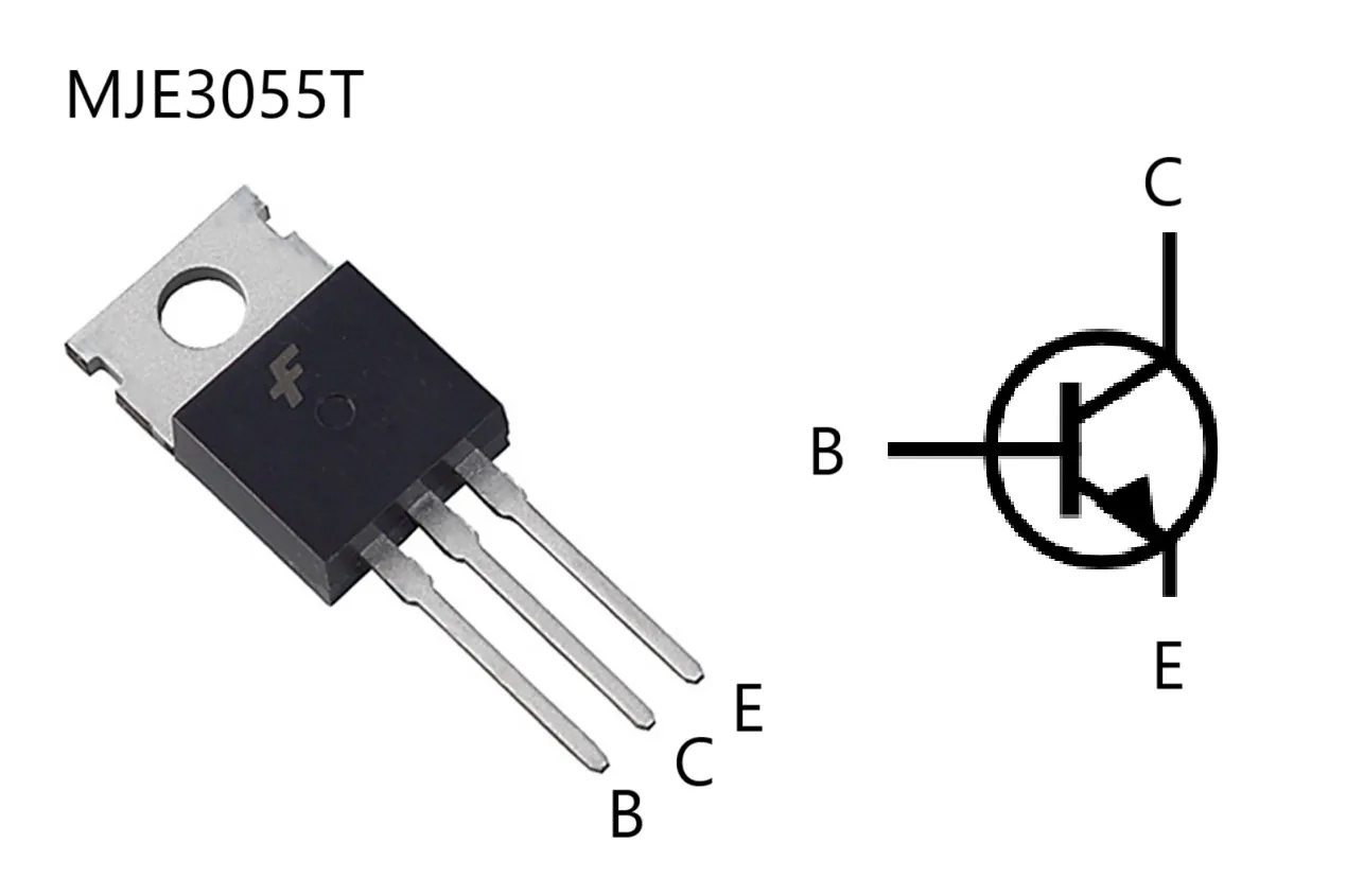
- Now connect everything together (don't forget the heat sink!) and give it a try! If you don't get any output (and the blue LED is not lighting up) simply try to switch primary connections on your terminal. If that doesn't help, try to play around with primary coil (generally 4-5 turns is good).
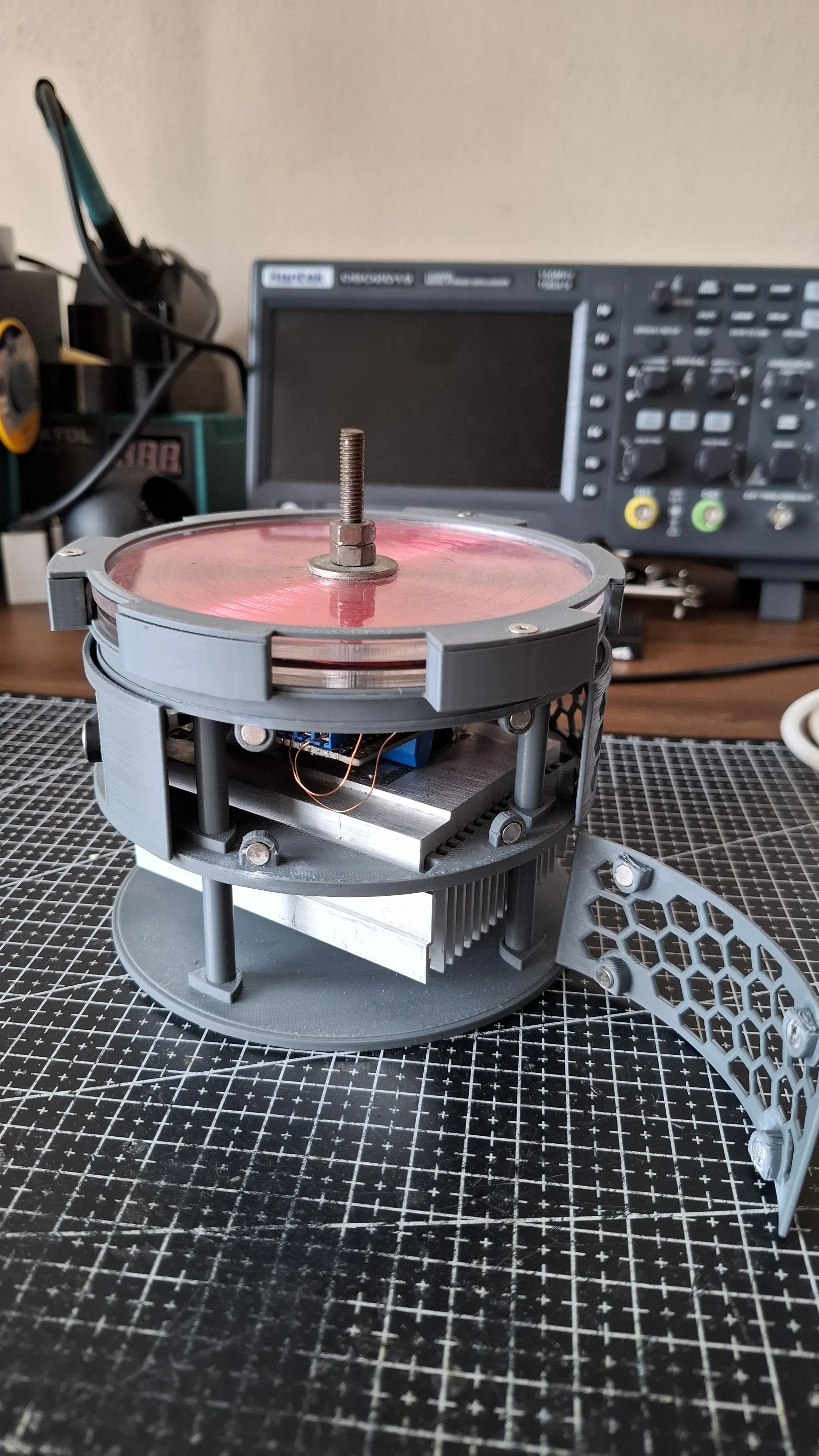
- If everything is working properly, we can now put all the things together, place the circuit and primary coil inside the case as shown below.
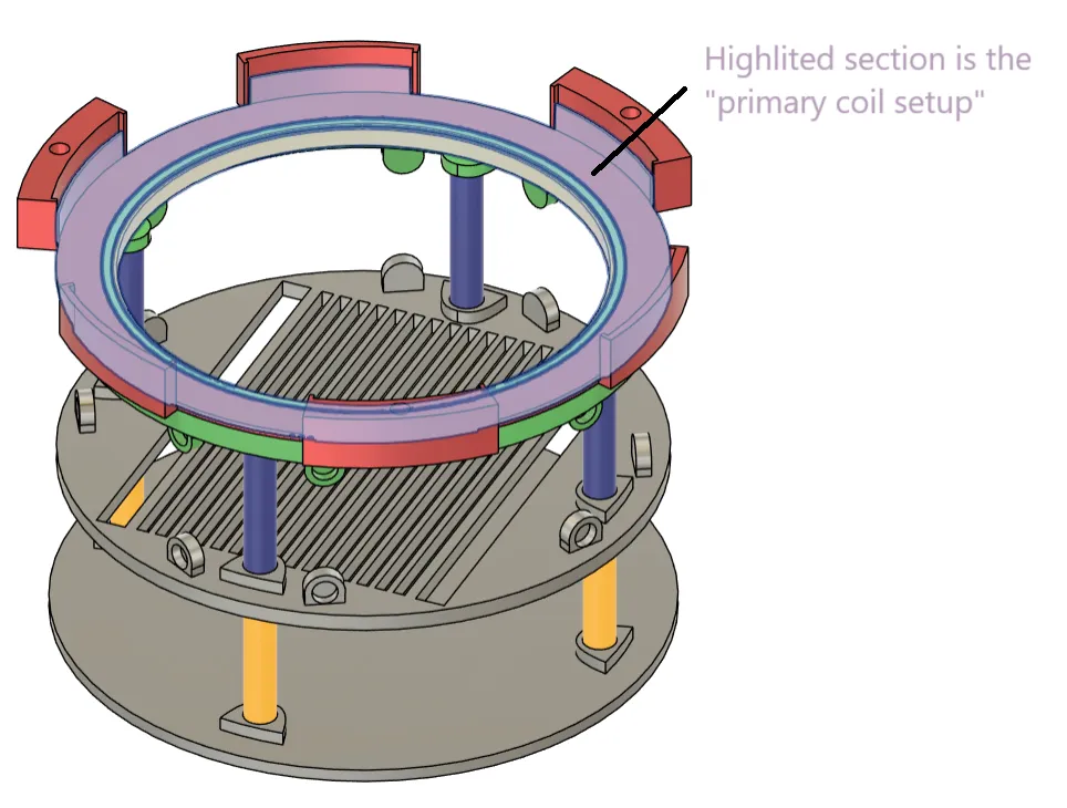
- Now simply add brass inserts into the holes in A2, then place secondary coil inside A2 and screw the top cover A1 on top using M3.
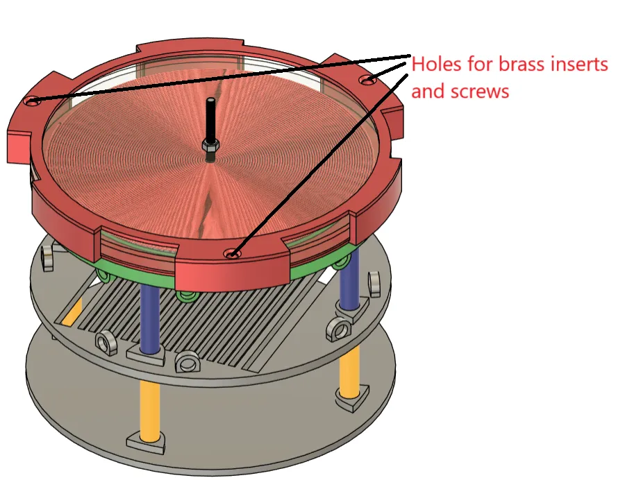
- After that we can insert (and glue) neodymium magnets in holes.
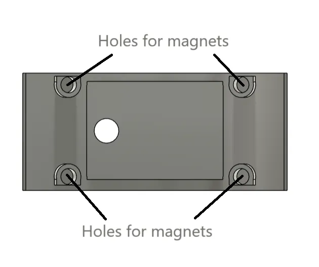
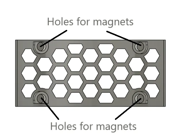
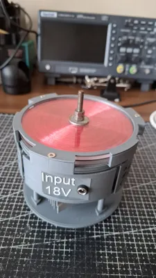
Now put everything together and enjoy your new Tesla coil!

License



Comment & Rating (3)