
Improved gears for portable air raid siren
Print Profile(1)


Description
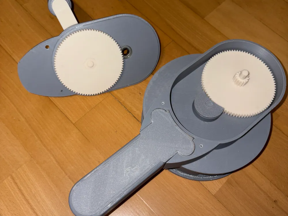
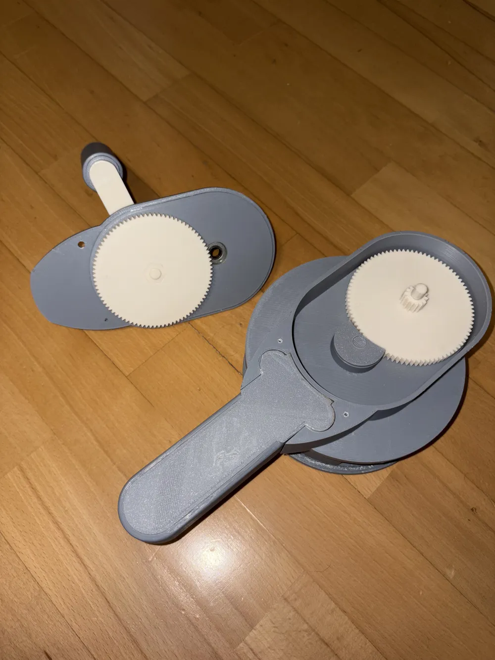
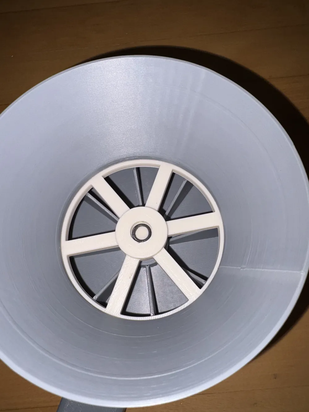
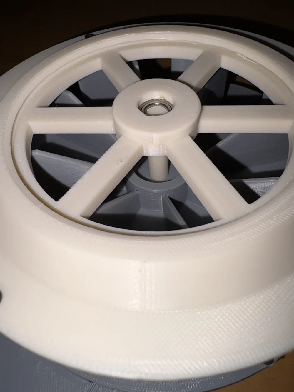
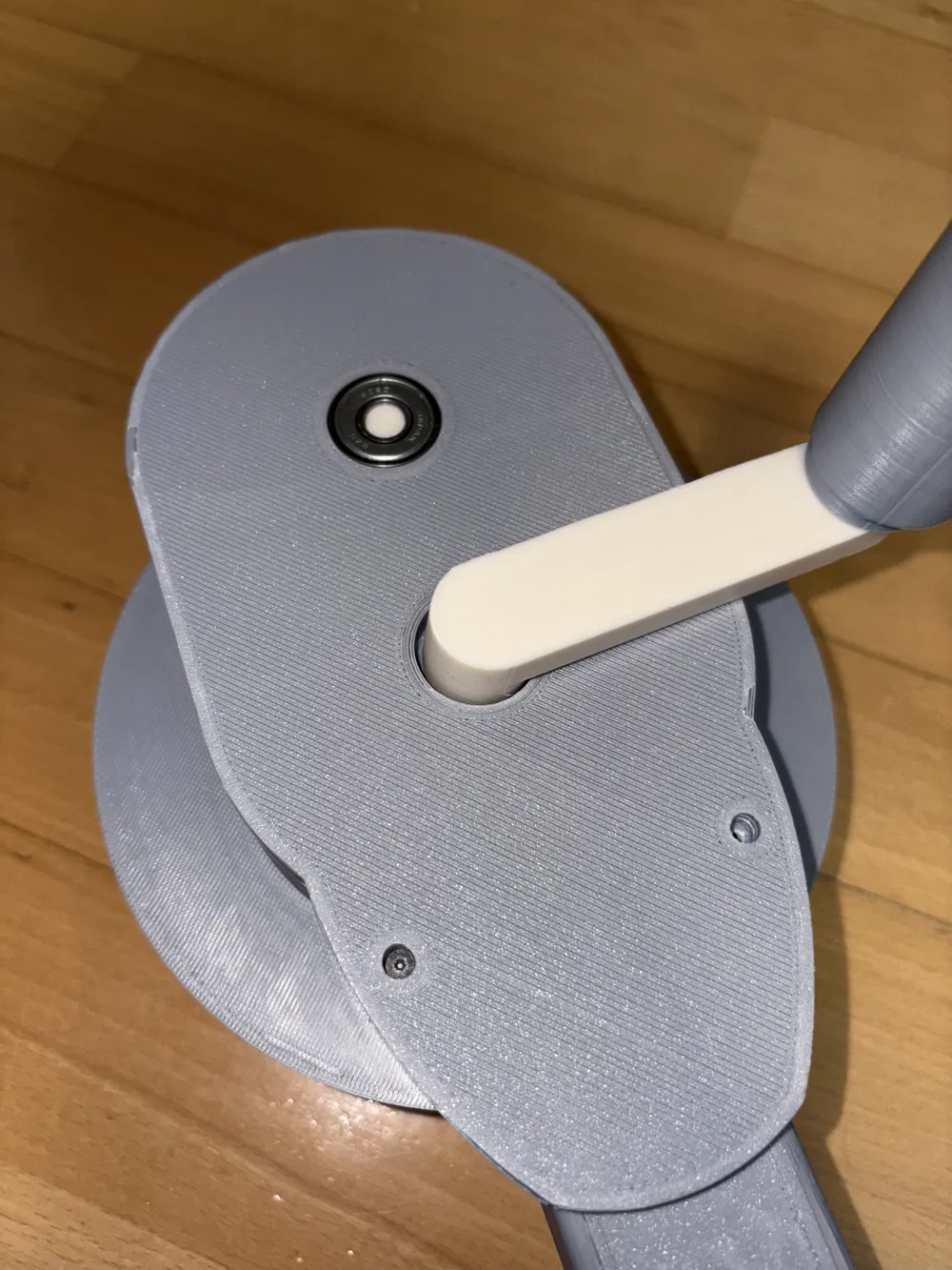
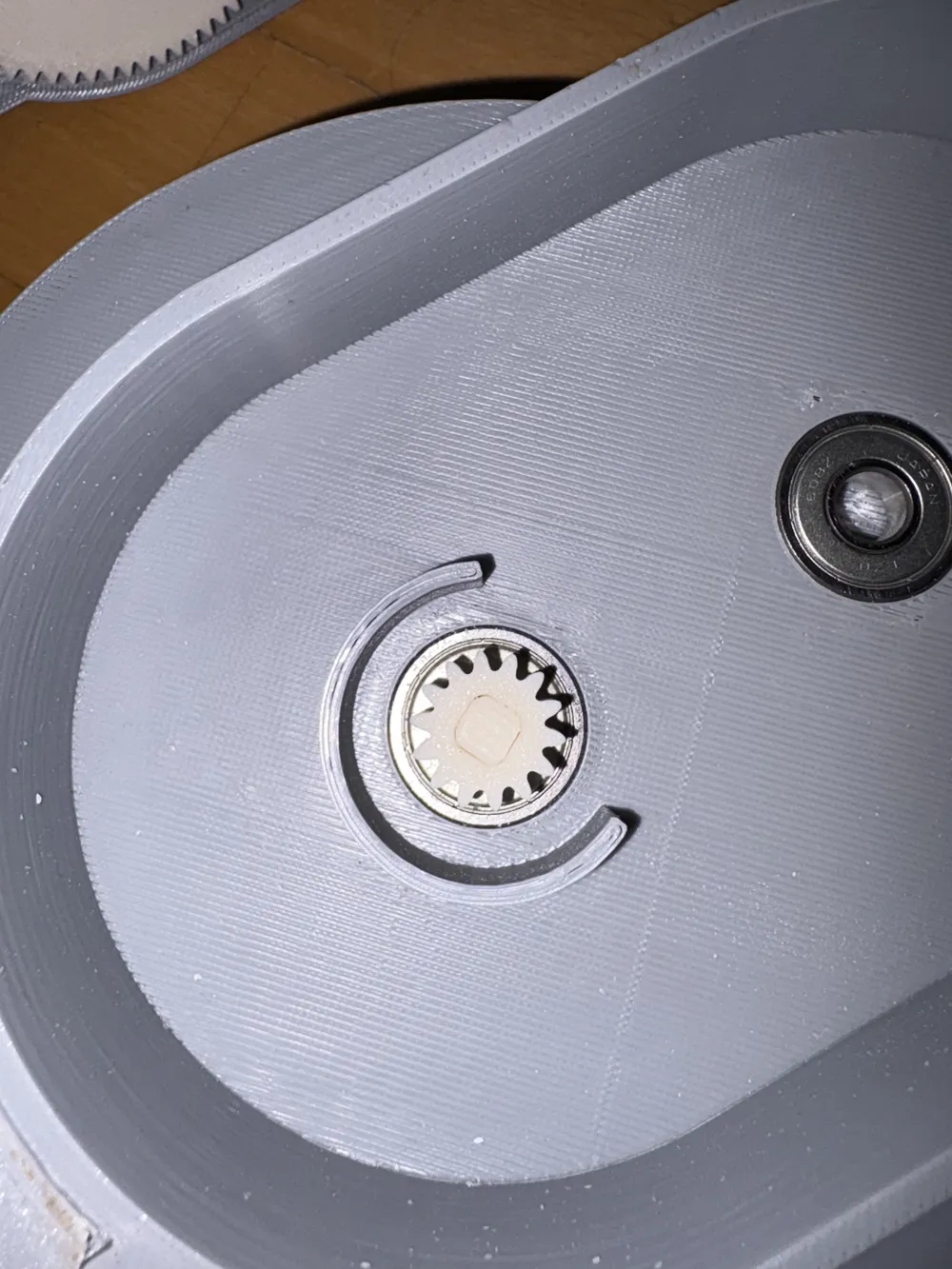
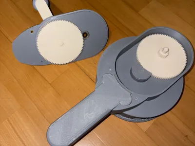
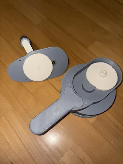
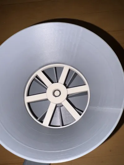
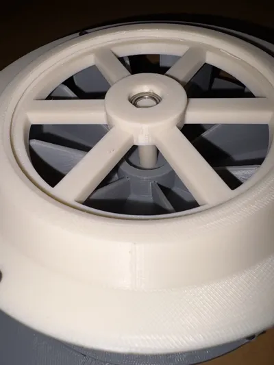
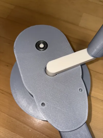
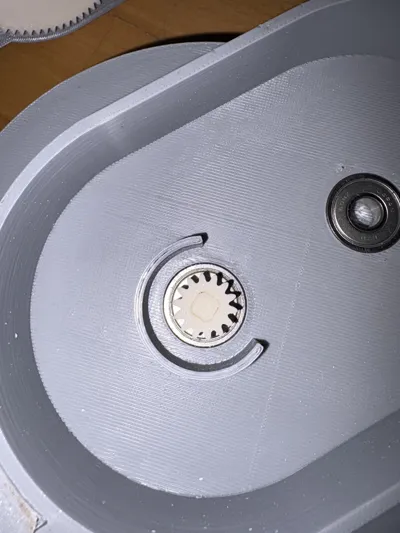
After I printed and assembled the siren, I noticed that after barely medium force, the shafts started spinning separately from the gears, even after I glued them, so I made these new shafts and gears with polygon connections, so no glue is needed for assembly (in my experience you won't even need to glue the rotor to its shaft) and it handles all the torque you put on them (I noticed that the gears start skipping teeth when I suddenly apply all the force I can), the tolerances are quite tight, so you'll need some force (and maybe some post processing) to assemble the components. All of these fit the original housing, since I just tweaked the original step files. I also shared my step files for easier modifications, if needed. I also made the crank handle grip longer, so you won't need to print that ring that goes on top of it.
Print orientations:
- shafts: c_shaft_rotor; c_shaft_midgear_6mm_1; c_shaft_midgear_6mm_2 - laid down on their sides (their axes is parallel with the print bed), use supports, will need some post processing to make their cross section circular
- gears: c_gear_rotor; c_gear_midgear_6mm; c_gear_crank - on their flat sides, this is trivial I think, no supports needed
- c_crank - on it's side, so the axes are parallel with the print bed, this gives the part the most strength (first I printed this part on it's flat side, and between layer lines, it snapped after 10 seconds of medium torque), use supports
- c_rotor_housing_cover - on it's flat side, also trivial, use supports
- c_crank_grip - standing upright, its axis is perpendicular to the print bed, also trivial, no supports needed, only if you know your printer can't really print reliably the rounded edge
I printed it from ABS and ASA, I encourage to use more heavy-duty/engineering grade materials for these high load-bearing parts
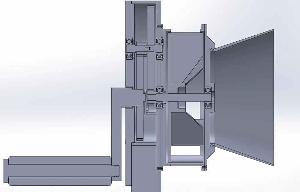
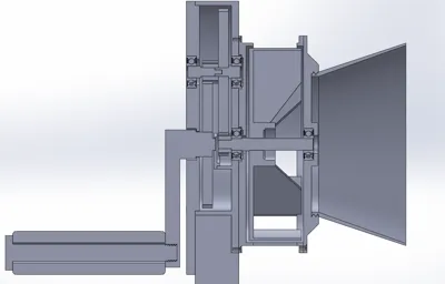
See cross section photo for correct assembly
This remix is based on

License



Comment & Rating (7)