Packintosh - Mac 128 mini-ITX PC case


Print Profile(1)

Bill of Materials

Description

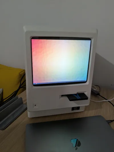
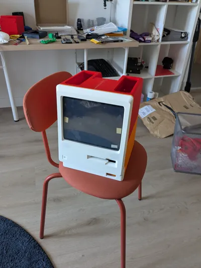
Meet Packintosh : a mini-ITX enclosure for PCs inspired by the legendary Macintosh 128
Features
- Mini-ITX motherboard support
- SFX PSU
- CPU cooler up to 75mm
- Horizontal GPU support up to 215mm, double slot width
- Vertical GPU support up to 268mm, double slot width
- Slot-in 2.5 inch drive bay
- 120mm or 140mm top exhaust fan
- Optional 2.5 inch drive support (120mm fan only)
- Integrated screen, using Ipad 3 glass and panel
- Integrated speakers
- Front IO
READ BEFORE PRINTING OR BUYING PARTS

- READ. THE. WHOLE. MANUAL. FIRST.
- Packintosh is a complex build. Do not expect a “print and play” model : this WILL require careful fitting, gluing, filing, sanding. I've done my utmost best to design parts that can be easily printed and assembled, but bad things can (and will) happen.
- Packintosh aims to fit a modern, 500W+ computer in a case designed in the 80s for a 60W computer. Airflow will not be good. Your components may suffer or break because of this, you have been warned !
- Packintosh can be printed out of PLA, but the result will be… less than convincing. ABS/ASA or better is strongly recommanded ; I personally chose ASA-CF for the dimensional stability, but any fiber-reinforced type of ABS/ASA should do just fine.
Parts list
- Approx. two kilos (two standard spools) of filament
- ABS/ASA, fiber reinforced recommanded
- Mini-ITX PC build
- SFX PSU (SFX-L technically fits, but it might be very hard to route cables)
- CPU cooler up to 75mm
- Two slot GPU
- up to 215mm
- up to 268mm if using the vertical mount, along with :
- A PCIe riser (200mm works well)
- A PCIe 270 degree bracket
- Extension cables for the GPU IO
- One top fan, 120mm or 140mm
- One 2.5 internal drive (120mm top fan only)
- Adhesive, like CA glue, and/or filament-solvent slurry (ASA in acetone worked well)
- M3 hex bolts of all sizes, 5mm to 25mm (buy a box, they are dirt cheap)
- Screws and bolt of approx. similar size can also work, but heads may not fit in the designed recesses
The following parts are not standardized enough ; I've provided the models to fit the ones I bought, but you may have to create your own ; here is the list for reference → https://www.amazon.fr/hz/wishlist/ls/2I9MYZEM4X2AF?ref_=wl_share
- Power button
- Front IO cable
- 2.5 inch drive connector/USB dock
- Integrated speakers
- Display and power cables
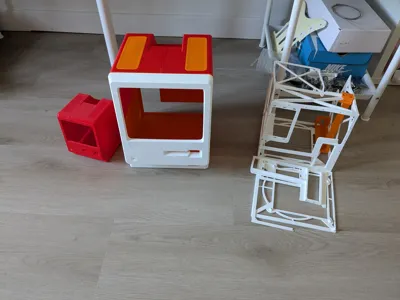
Building
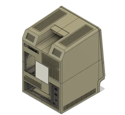
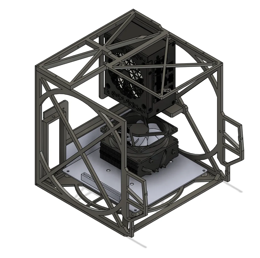
Inner chassis
Print the five parts of the inner chassis, and glue them together using the indexing holes to ensure good alignment. A piece of filament should fit, but if the hole is too narrow, use a purge line from a print start (the long L shaped thingy).

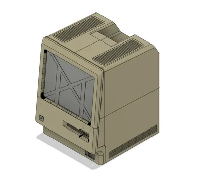
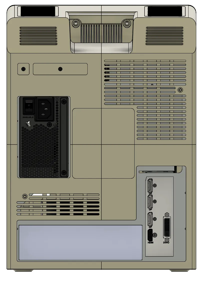
Back case
Print the four parts and two accessories plates. Keep the four feet and two vents aside for later. Glue the front wings first to the back parts ; you should now have four quadrants of the back. Glue the top quadrants, then the bottom ones ; then glue the top and bottom together.


Front Plate
Print the two parts. Glue the parts.

Optional - Vertical mount
Print the mount and cap (and PCIe bracket if you extending cable fit, or remix the models so that they do). You can then slide the mount in the inner chassis and secure it with the cap and two bolts.

Other Parts
The other parts print don't have any particular instructions (drive parts, badges, screen holder and face IO)
Post-Processing
I am not good at post processing. Follow a proper guide for this ! I filled all deep grooves with plastic filler, sanded, primed and painted. It does not look great, but I don't mind all that much.
Assembly
When everything is printed, you can begin the assembly. I would advise tapping the holes for best results.
Face Plate
Assemble the drive parts with the face plate. If you have a SATA/U.2 connector, you can secure it to the top part of the drive slot. Speakers can be slotted in the two recesses. The screen glass can now be fixed to the frame. For alignment purposes, I recommand that you glue the screen to the glass with a mild adhesive ; use a test target to properly align the corners. Use the screen holder to help holding everything together (adhesive helps !). Fix the front IO and power button to the frame.


Once all done, cable manage everything as best as you can. I chose to stick the screen controller on top of the drive slot, but you can also stick it to the back of the screen holder.
Inner chassis
Start by attaching the top fan (hidden in the next pictures for visibility).

Prepare the motherboard with every component except the GPU and 2.5 drive. Screw in the board to the chassis (the 4th bolt, near the PSU, will be extremely hard to get. I skipped it entierely)

Place the PSU in the slot and secure it with screws.
For regular GPU mount, place the GPU. You should route your internal display cable using the notch at the top of the PCIe opening.

For vertical GPU, prepare the IO extension cables by plugging them on the card. Plug the PCIe extension in the motherboard, and the 270 degree bracket on the extension. Line up the bracket with the vertical mount, and seat the GPU while routing the extension cables. Screw in the card. Assemble the PCI back bracket with the extension cables, and secure to the back opening.

If you have a 2.5 inch drive, place it on the bracket on top of the chassis.

Mating the face and chassis
Tidy up both parts, and identify the cables that will cross : front IO cable (USB3.0), power button, screen power cable and display cable. Bring the two part close, plug the cables. Screw the face to the chassis with four bolts, and secure the drive slot to the chassis with a bolt.


Back case
Attach the feet by either screwing or gluing. A felt or rubber disc can be added to avoid scratching surfaces.
Rest the whole front assembly on its face, and slide the back case over it. You may have to manoeuver the back to get it to properly. Use the two holes at the back to screw the case to the chassis.
You can also use two extra long bolts in the carry handle recess (like the original !), using an extra long screwdrive. I did not bother. It hold fine without them.
Last step ! Place the vents and apply the badges :)

Comment & Rating (50)