Wearable Iron Man 3 Arc Reactor (soldering)


Print Profile(4)


Description
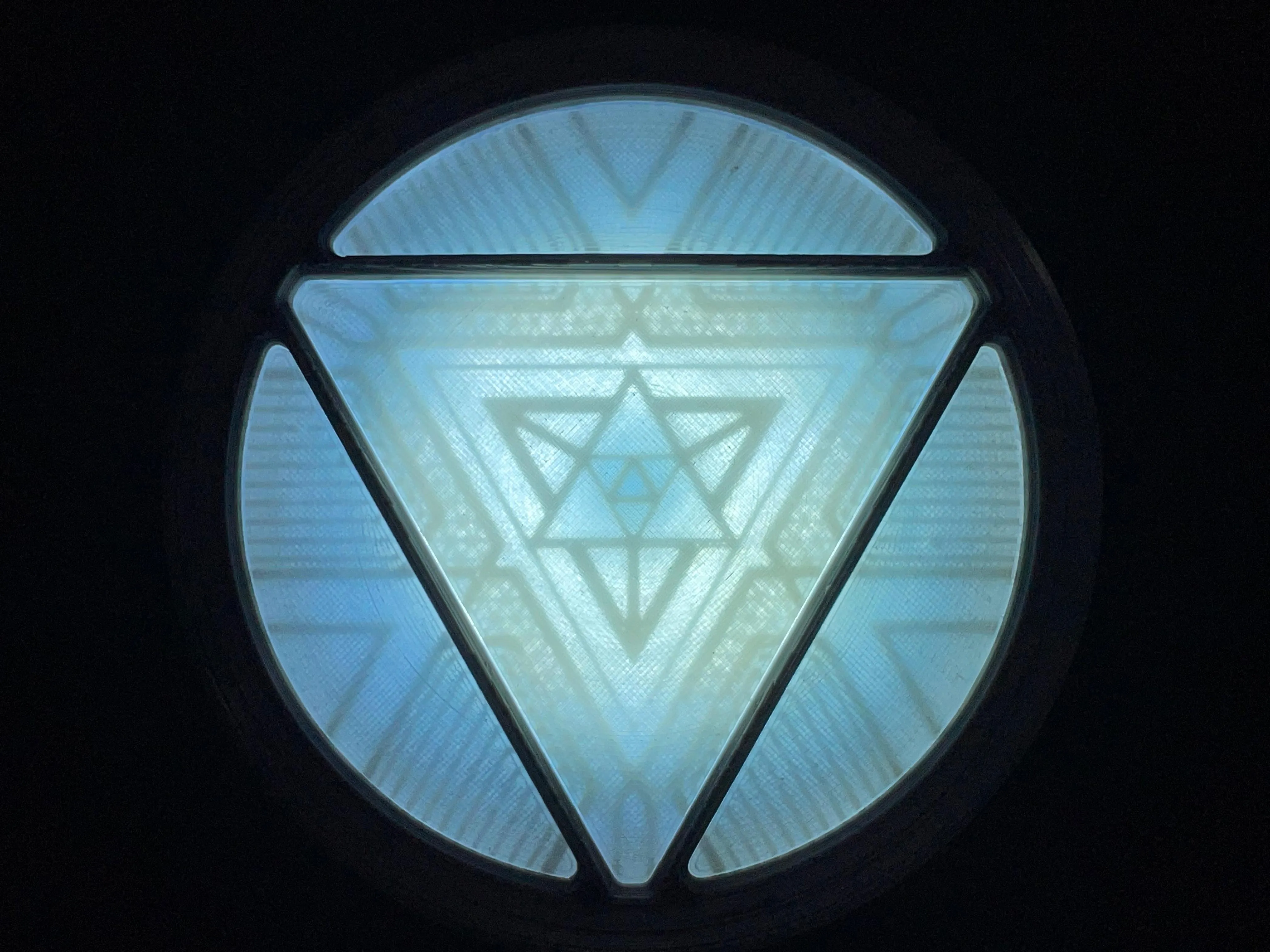
V2 Lighting now released!! Only compatible with AMS version as of now!!!
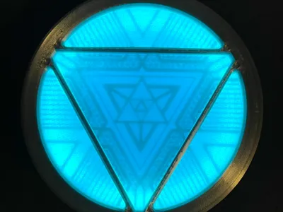
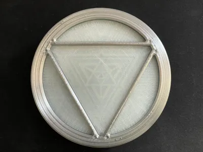
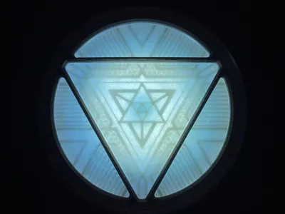
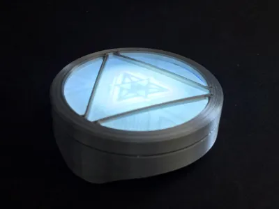
First two photos are V2 lighting, the rest are V1 lighting. V1 lighting files still included in the print profiles but deactivated by default.
V2 is a drop in replacement if you already printed V1!
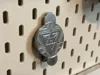
Magnetic mount for an IKEA Skadis board available as a print profile!
Uses two 10x3mm magnets just like the reactor

This project was inspired by this model on Thingiverse. Go check it out and give it a like because the creator Neon172 did a really fantastic job! He has some other Arc Reactors that look phenomenal as well and they're all free so go show him some love!
I used two parts from that model with permission of the creator, both of which are modified and have many hours put in to them so while I considered uploading this as a remix, I believe I'm justified in uploading this as an original model and also have the permission to do so from Neon172. I didn't just copy/paste anything and I have a bunch of iterations with test prints and file versions to prove it ;)
Boost Me (for free)
Finalizing all the details of the mounting system, making the geometric details more accurate and finding the best parts to use took a lot of time (and some money on parts i ended up not using), a boost would be very much appreciated!
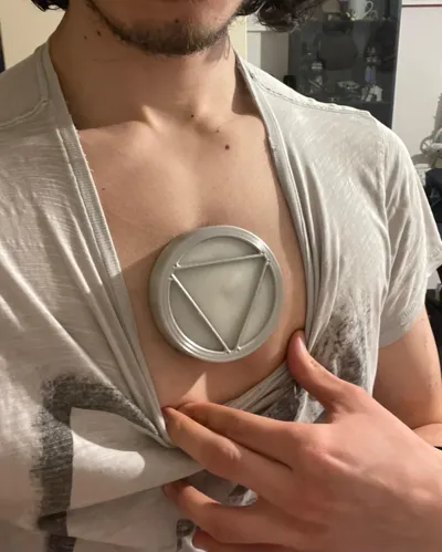
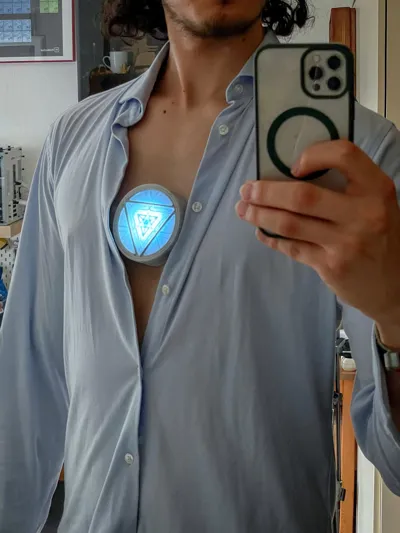
This arc reactor uses magnets to mount to your chest so it looks like it's actually built into your chest! By far the most realistic mounting system aside from just gluing the whole thing to your chest like they did in the movies (which you could still do with this one, however that's a lot more adhesive to remove and limits your options for adhesives). Scroll down to the end of the description for mounting instructions.
How to change the shape to fit better (Fusion)
The shape of the mount is modeled to fit my chest, which should fit most males decently. You can make modifications to the “chest plane” form in the Fusion file “bodies” folder, just edit the feature in the timeline (purple cube icon) and edit the form. Change the form to fit your chest shape and it'll automatically adjust the model shape. Small changes should be fine, but no guarantees that it'll work out.
Nozzle Size
Everything is made to be printable with a 0.4mm nozzle, however I do recommend printing the detail plate for the non-AMS version with a 0.2mm nozzle. A 0.2mm print profile for that part is provided.
Which Lens to print - AMS or non-AMS
I strongly recommend printing the V2 Lighting AMS profile (read the following warning!) which has a Lens with embedded details as this provides higher screen accuracy and much better visibility of the details, however if you don't have one there is a non-AMS profile with a normal Lens and a Detail Plate you can print. The geometry won't be as visible though because the plate is closer to the light source and further away from the Lens surface. Below you can see a comparison of both, the AMS version on the left is clearly more detailed. I might still work on a better non-AMS version, but no promises on when that will come out.
WARNING
Eryone PLA Glow (see the parts list) has some difficulty feeding with the AMS Lite in my experience. I was still able to print with it, however I had to fix feeding issues multiple times across multiple different test prints. This didn't affect the quality of the print as far as I can tell, however it can be annoying. Just keep an eye out on the printer if you use the same filament. If you find a suitable replacement then feel free to post in the comments and add a picture of it, it's always good to have alternative filament options.


Parts needed
- Eryone PLA Glow blue - works incredibly well for the Lens (not because of the glowing, but because the normal color looks like the milky glass of the original reactor) - Aliexpress link
- Bambu PLA Silk+ Silver
- Bambu Transparent PETG Blue
- Double sided tape
- Super glue
- 6x Magnet 3x1.5 mm
- 4x Magnet 10x3 mm
- LED Strip - Aliexpress link - NEW - edge lit V2 Lighting
- Li-Po Battery - Aliexpress Link
- 1.25mm JST connectors - Aliexpress Link
- Heat shrink - 2mm, 3mm (more than 3mm if your resistor is thicker)
- Toggle Switch SS-12D00G 3mm - Aliexpress Link
- 10 Ohm Resistor
- LED Panel - Aliexpress link - OLD - center lit V1 Lighting - I highly recommend the new edge lit version, however it's here if you really want it
The resistor was mandatory for the old lighting as the panel will get super bright and very hot without it. The new edge lit version doesn't necessarily need one as it doesn't get as bright and hot as the panel, however I still highly recommend using one to set the current for 3-3 ½ hour battery life. The brightness increase is small so it's not worth running without imo - haven't measured the current draw without so I don't know the battery life without it
- Sandpaper 60-3000 grit (optional but highly recommended, the Lens looks WAY better sanded)
- Prosthetics Glue (Spirit Gum) - a Bandage or skin safe tape might work well too if it sticks enough
Disclaimer: I am not a medical professional. I am not responsible for any damage done to your body by using products I have listed. I am merely listing things that work for me and on my skin. DO NOT JUST TAKE MY WORD FOR IT. I'm a stranger on the internet, you must do your own research before sticking anything to your skin or using any medical products. Consult your doctor and/or skin care provider to see if there are any issues with any of the products that can be used for this purpose and follow proper instructions for whatever you use.
Sanding
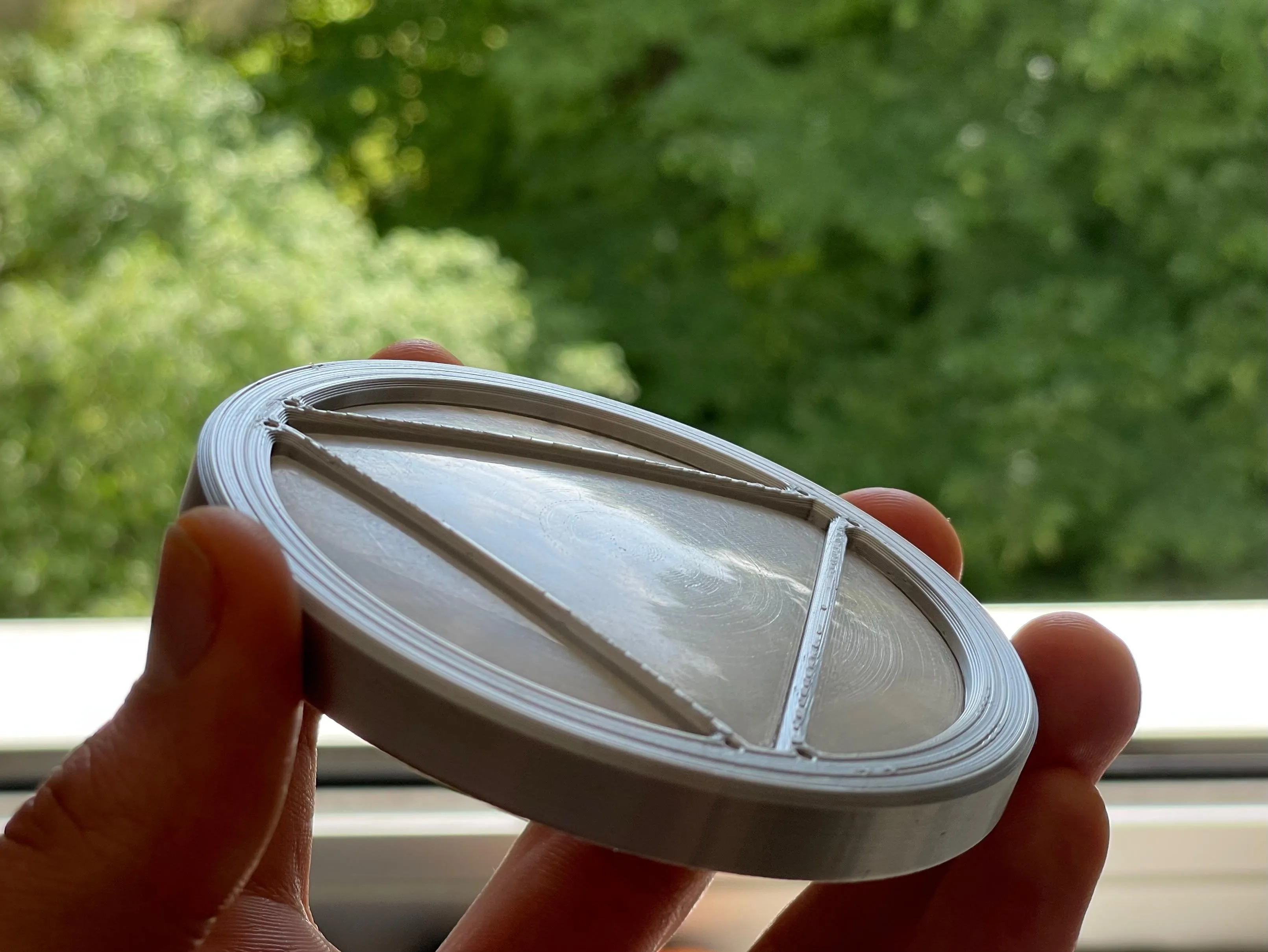
I highly recommend sanding the Lens. Eryone glow PLA is fairly easy to sand after you get it roughed up with 60 grit.
I used an electric hand sander for 60 and 120 grit, after that wet sanding with 240, 400, 600, 1000, 1500, 2500, 3000. 60 grit definitely takes the most time, but after that it's really fast. Just spend about 2-3 minutes on every wet sanding stage and you can get it reflecting almost like real glass.
In the picture you can see the trees and blue sky in the reflection and it looks even sharper in person. It really doesn't look like plastic until you get close and can see the printing lines, so sanding makes a huge difference. Definitely worth the effort in my opinion.
Sanding the bottom of the Lens up to 400 grit can also help get rid of some scarring from the supports which can be visible when light shines through.
The AMS version is printed using PETG supports which makes the removal much easier while also leaving basically no scarring from supports. Just make sure you're using PETG, if not then change the support settings back to default.

Assembly

Glue 3 3x1.5mm magnets in the spots marked in the picture.
I chose to have the top two facing one way and the bottom one by the seam facing the other way so that the seam is always on the bottom when wearing it.

Glue 3 more in the corresponding spots in the shell as seen in the picture.
Be sure to check the orientation of each magnet so the cover is attracted and not repelled.
If in doubt, let a magnet stick to the corresponding one in the Cover and use a sharpie to mark the exposed side. That marked side has to be glued down.

Next glue 2 10x3mm magnets in the bottom of the shell.
If you want, you can put some glue on the inside of the shell where the top magnet pokes through to make sure those cracks are filled.
Next, fit the Lens into the Cover. Glue isn't needed here.

The next step depends on if you printed the AMS version or not (the picture shows the non-AMS version):
AMS: Blue Transparent Plate
Non-AMS: Detail Plate
Insert the Plate after the Lens into the Cover with the bottom of the plate facing the Lens. There are three small protrusions in the Cover so the Plate snaps into place without any glue. Be sure to push it all the way until it snaps in on all three protrusions.
The next steps require soldering.
Basic soldering tips
- Heat up the thing the solder is supposed to stick to (wire/pad/pin) and touch the solder to that, not directly to the tip of the soldering iron. It sticks much better that way.
- Put some solder on each surface individually (tinning), then put them together and heat both surfaces with the soldering iron simultaneously. The solder that's already on them will bind them together.
- If your solder joint is ugly and pointy, put some flux on it and remelt it
Cut the LED Strip at a length of 22.4 mm. This should be 9 segments. Remove the heatshrink and desolder the wires that are pre-soldered. Replace them with at least 20 mm long wires with a male JST connector (the one with pins visible). Solder the red to the + Pad on the LED Strip and the black to the - Pad. After that, remove the adhesive and stick the strip to the inside radius of the Separator Plate. Make sure the wires and solder blobs fit in the opening in the radius.
For the switch you'll need one male and one female JST connector. The LED Panel takes way too much current and would sear your eyes and start melting the PLA within about 10 seconds (don't ask how I know that), so we need a current limiting resistor. I used a 10 Ohm resistor for this, however you can go slightly higher if you want even more battery life (not over 50 though). The light will get dimmer the higher you go, so try some values out if 10 Ohms is still too bright for you.
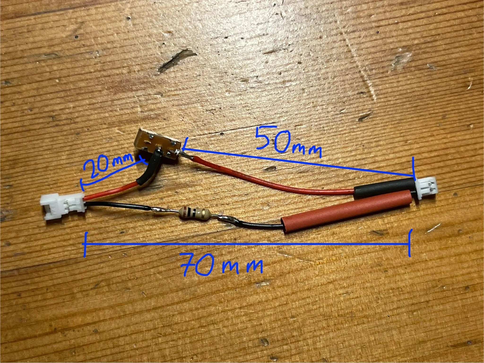
See the image for how this is wired together.
The red wire of the male connector (left) should be ~20mm.
The red wire of the female connector (right) should be ~50mm.
The black of both connectors plus the resistor should be ~70mm. (The black being a tiny bit shorter than the entire red connection makes it naturally bend which is beneficial later)
Cut off one of the outer pins of the switch. Orient it as in the picture, bending the middle pin down and the right pin out, making sure they don't contact the housing anywhere. This makes mounting the switch and routing the cables easier.
Be sure to put the heat shrink on the wires before soldering them (don't ask me why I mention that…) and make sure they're far enough away from the soldering joints so they don't shrink due to heat conduction in the wire.
Solder as seen in the picture (male red to middle switch pin, female red to right switch pin, black to resistor to black).
Before you put the heat shrink on, push the switch so it's on the side of the pin you cut off (off position), plug in the battery and LED Panel and turn it on to make sure everything is working.
The switch bridges the middle pin with the pin on the side it's pushed to, so push it to the side the cable is connected to and the LEDs should turn on, push it to the side with the cut off pin and there's no completed circuit so no current flows.

If it's working, turn it off and unplug everything. Cover the solder joints with the heat shrink and shrink them to cover any bare metal as seen in the picture.
That's all the soldering done!

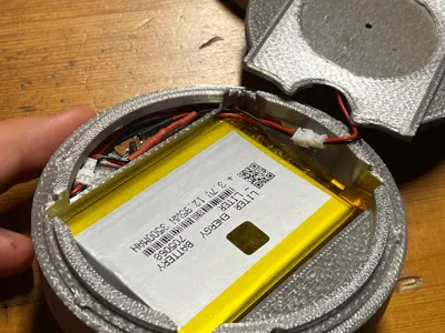
Feed the battery wire into the hole in the Shell and feed it through.
Add a strip of double sided tape to the bottom of the battery and stick it to the shell. Don't use so much so you can't remove it, this is just to keep it from rattling.

Now plug it into the switch circuit and feed the female connector of the switch circuit through the hole in the opposite direction of the battery wire as seen in the next pictures.


Place the switch into the Shell. If it doesn't go in straight, check to see if there's some filament from the supports or a bad layer stuck in there that's making it uneven.
The switch should sit tight enough to not need glue, however if it comes out easily you can use some super glue on the sides of the switch. Not on the bottom, otherwise you might get some inside the switch mechanism and glue it in place. Also, glue is generally supposed to keep something from sliding, not from pulling apart so the sides are better.

Check to make sure the switch is off and plug in the LED Panel.
V1:

Push the Separator Plate into the Shell and push any excess cable into the space between the battery and Shell to make sure it doesn't cast a shadow by sticking up.
V2:
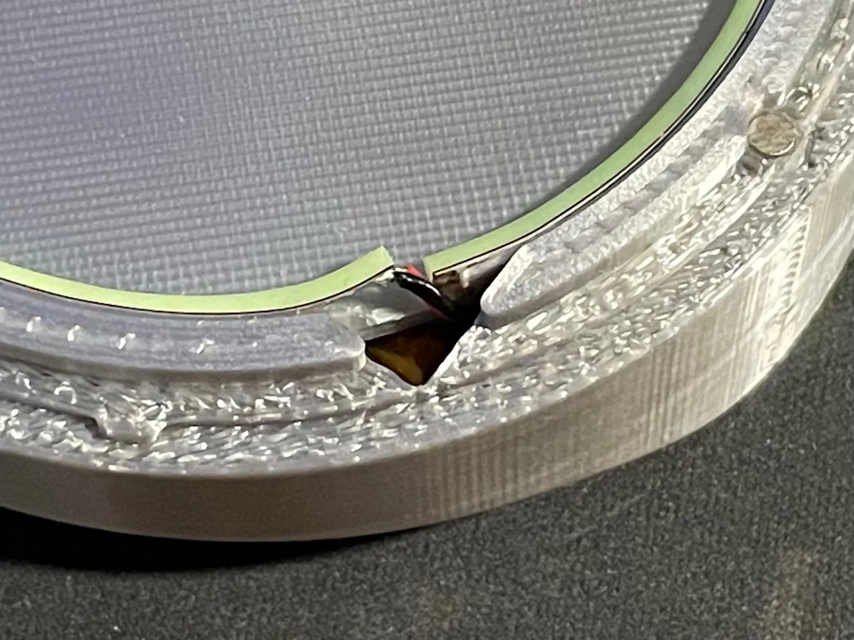
The cable goes through the hole in the corner. If the strip is lifted slightly like in the picture, be sure to stick it down to the radius. Use super glue if necessary. This ensures even lighting around the whole edge.
If you printed the non-AMS version, insert the Blue Transparent Plate now. Make sure the round cutouts line up with the magnets.
Put the Cover on, flip the switch and you're done!
Enjoy your “fully” functional arc reactor!
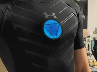
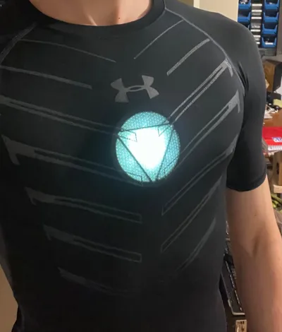
Add a compression shirt for the full Iron Man 3 garage look ;)

How to wear
The mounting system is magnetic, so no straps or harnesses required.
The way I’ve worn it so far is by using skin safe adhesives to stick the magnets to my skin and then attaching the reactor to those. Alternatively, you can use magnets in other ways to mount it, for example using a skin tight shirt and magnets behind that. You could wear that under a compression shirt so it doesn’t sag. Or if you don’t mind harnesses, add some magnets to a harness and wear it like that. I believe magnets give you the most freedom to wear it in a way that fits for you.
Read the disclaimer I wrote earlier, I'm not responsible for anything you stick to your skin or any damage done by removing something you stuck to your skin. Do this at your own risk and do your own research.
Take the two 10x3mm magnets that are still left and whatever adhesive you're using.
If using tape/bandage, you can just stick it between the magnets and then push the reactor against your chest. Carefully slide the reactor away to separate the magnets without pulling the tape off and secure the tape on your skin.
If using glue, you can do the same with some clear packing tape and then you can see exactly where the magnets need to be glued. Then secure them with glue in a way that the remover can still get to it so it's easier to remove later.
Now you just need to clip the reactor on the your chest and the magnets will hold it in place.
Tips for spirit gum:
Make sure it's tacky when you stick the magnets to your skin. Put some tape or bandage over the magnets so that there's a slight gap between the magnets when you put the reactor on. This makes it much easier to remove, reducing the chance that the magnets will pull away from your skin when you take the reactor off. It also helps take some of the force off of the spirit gum.
You should have pretty much full range of motion, however depending on you well built you are, compressing your pectorals too much will cause it to pop off. Move around a bit to get a feel for that. You can add another pair of magnets in between the reactor and the ones glued onto your skin to add raise the reactor if you need to.
If you use a compression shirt its should stay in place pretty well on its own when just walking/standing so in a pinch you can just have the compression shirt hold it in place. You might have to adjust it every now and then but if you're not comfortable gluing/taping anything to your skin or your skin doesn't do well with that it's still possible to wear it like that.
Charging the battery

You can use a USB C Battery Voltage Regulator board like a TP4056 to charge the battery.
Just solder a male JST connector to the board, red to B+ and black to B- and plug in a USB-C cable.
Just a tiny bit more soldering, even simpler than what you just did for this project.
The board will charge the battery to 4.2V and stop which is what you want.
Just unplug the battery from the switch and plug it into the charger.
You can print the shell I made for a USB-C TP4056 here
Boost Me (for free)
If you made it through all of that, congratulations! I hope you enjoy your arc reactor :D As you see, a lot of work went into making this and writing the instructions and if you haven't already, I would really appreciate a boost. It really helps to allow me to continue making things like this.
None of the links provided are affiliate links, I just like using Aliexpress for electrical components
License
You may create derivative works based on this object, provided that all such derivative works are published exclusively on the MakerWorld platform and include proper attribution to the original creator. You may not share, upload, host, distribute, or publish this object—or any derivative work of this object—on any other digital platform, marketplace, or distribution channel. Commercial use of this object and any derivative works is strictly prohibited. This includes, but is not limited to, selling, renting, sublicensing, or using the object in any context in which you receive monetary compensation or other financial benefits.
Comment & Rating (25)