
Lumetra - modular photography stand system
Print Profile(8)


Bill of Materials


- 1/4" 20-UNC 1", 7/8" or 1 1/4" screw x 1: for the top mount
- M3x20 screw if 1/4" is unavailable x 1: for the top mount
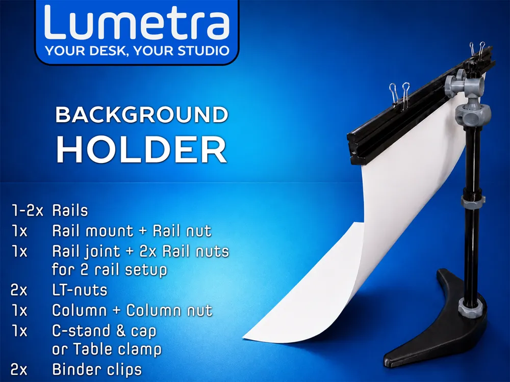
- binder clips x 2: for the rail holder
Description
The Lumetra system keeps growing with new modules, attachments, and more. A dedicated Lumetra Collection was created to keep everything organized. Check it often and follow me for updates!
All changes and updates related to this model set are listed at the end.
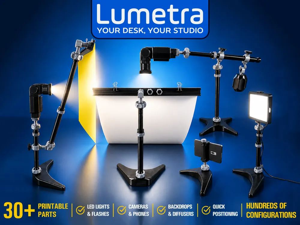
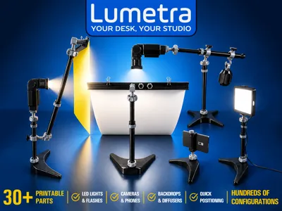
Lumetra is a modular stand system designed to simplify the setup of lights, light modifiers, cameras, and backgrounds for product photography. With over 30 parts, it offers hundreds of configurations and supports a wide range of accessories, helping you achieve professional results right from your desk.
Featuring extendable columns and ball-joint connectors for easy positioning and adjustment, Lumetra allows for versatile use for:
- LED lights or Photo flashes
- Smartphones and small cameras
- Backgrounds - paper, plastic, fabric, or printed backdrops
- Diffusers, color gels and reflective sheets
The Ball joints provide 360° rotation around the vertical axis and up to 50° tilt in any direction, giving you flexible control over the arrangement of your equipment.
Components Overview
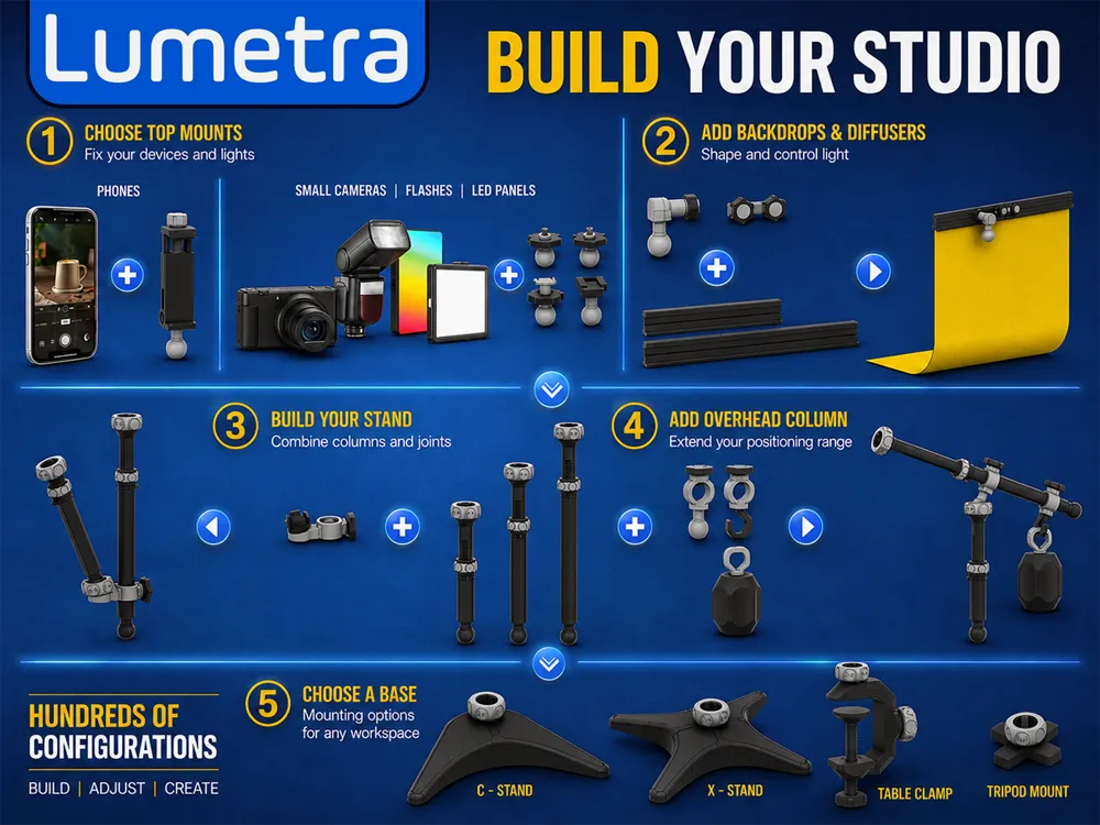
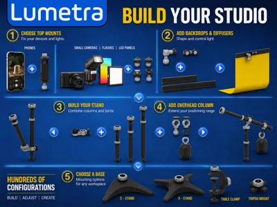
Lumetra includes four main parts: base, columns, top joints, and optional specialized joints.
Base
Allows for attachment of columns or equipment directly.
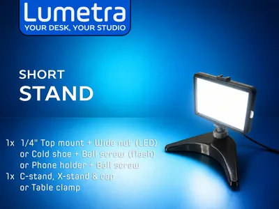
- C-shaped and X-shaped weighted stands for on-desk use
- A clamp for attaching to desks, doors, windows, cabinets or other furniture
- Tripod mount adapter for standard photographic tripods
Columns
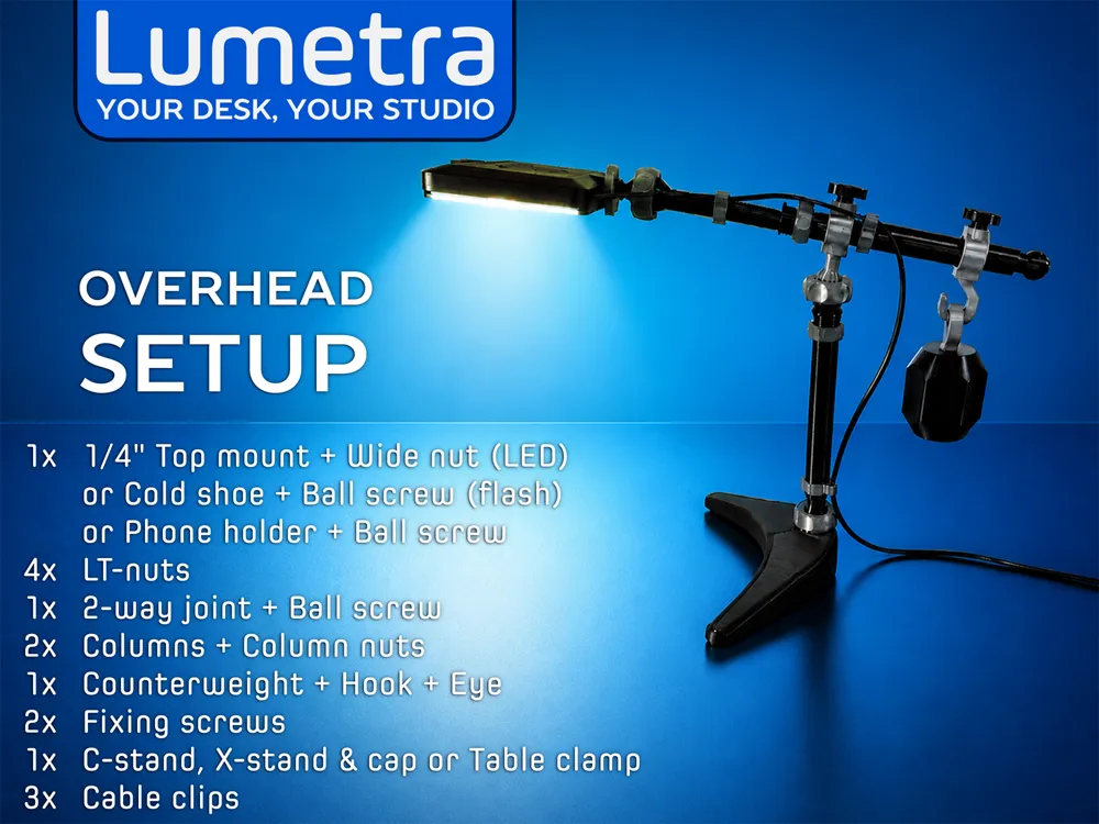
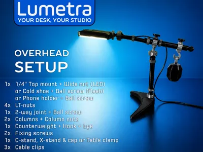
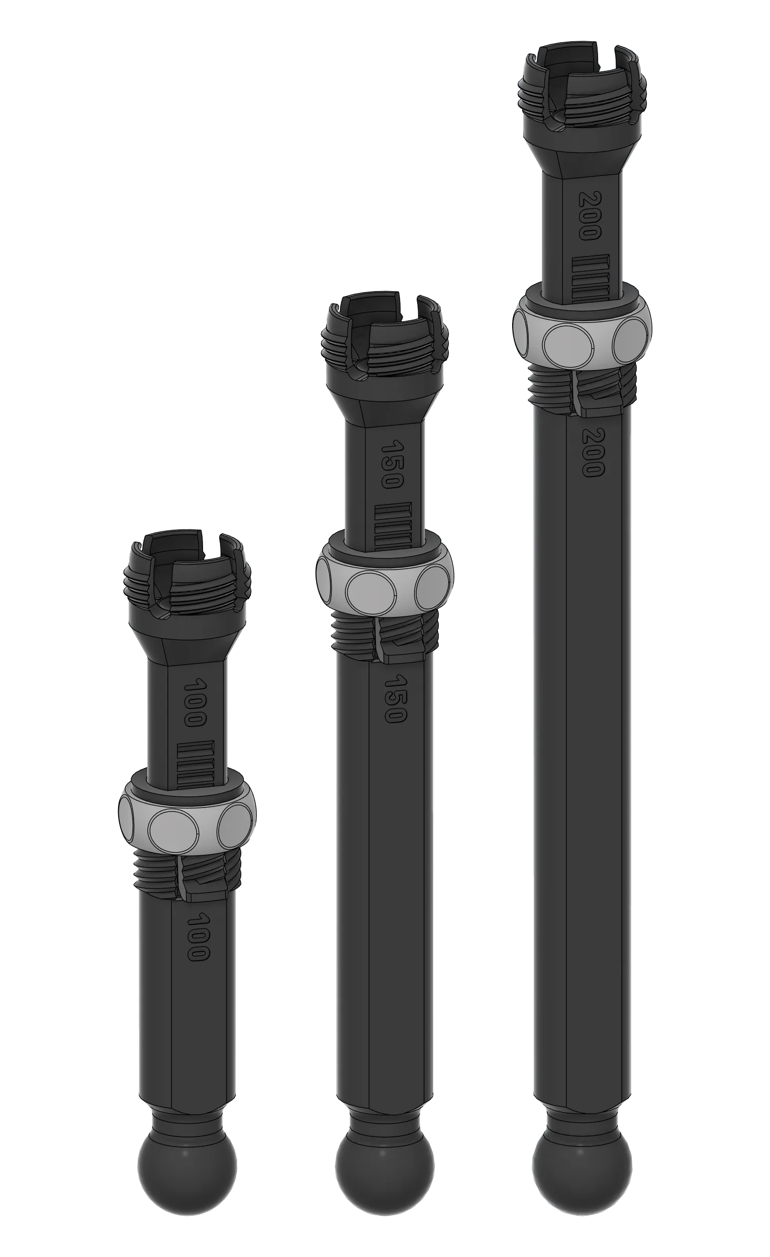
Three extendable sizes are provided - 100–130 mm, 150–230 mm, and 200–330 mm. Use individually, stacked for height, or joined perpendicularly for T-shaped overhead setups for top-down lighting or shooting.
Top Attachments for mounting various equipment:
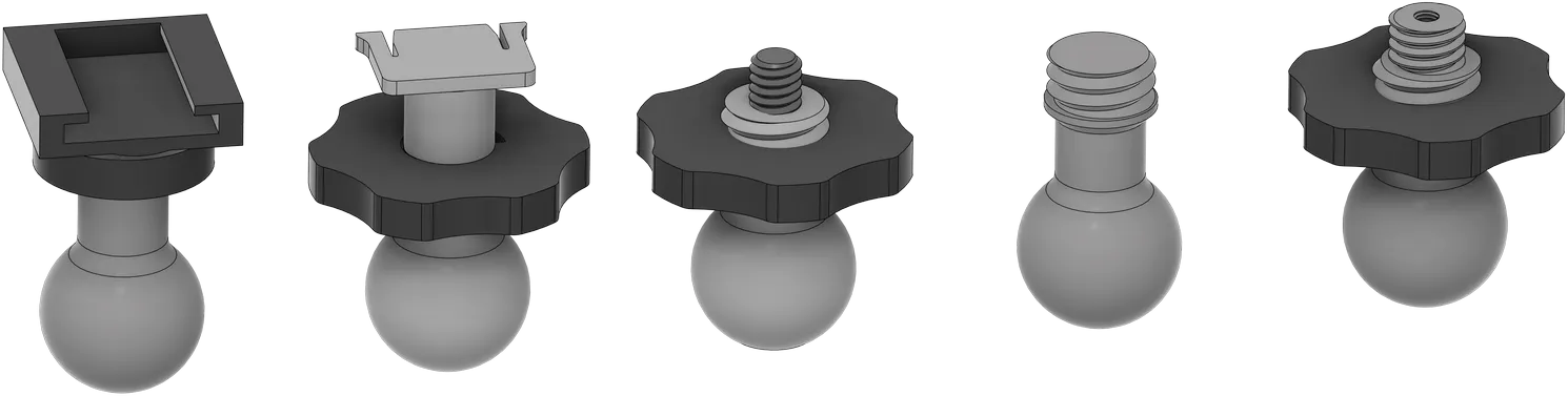
- 1/4" screw ball joint for LEDs, cameras, and accessories
- 3/8" screw ball joint for compatible photo gear
- Cold shoe mount for flashes or LED panels
- Flash-style adapter for LED panels with cold-shoe-like bases
- Phone holder for flexible phone positioning
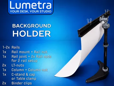
- Modular rail for backgrounds, reflectors, diffusers, or light color filters
Specialized Attachments for expanded functionality:
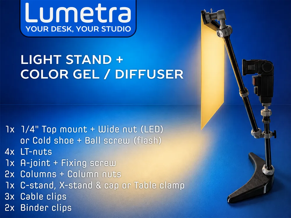
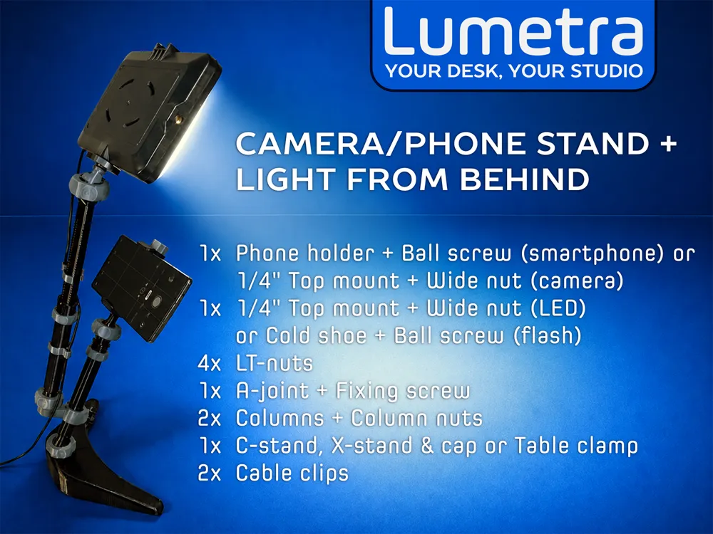
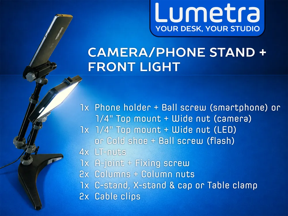
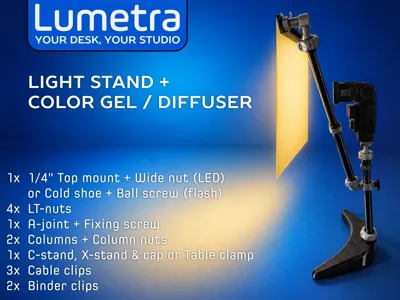
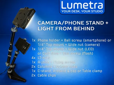
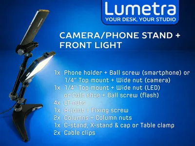
- A-joint for adding a second column alongside, useful for positioning a camera or smartphone behind/in front of a light, or for holding filters or diffusers in front of a light source.
- 2-way joints for perpendicular column connections or hanging a counterweight.
- Counterweight for stabilizing perpendicular setups
- Cable clips to keep cables organized along the columns
Printing and Assembly
All parts can be printed on a small printer like the A1 Mini, except for the 200 mm column. Use PETG or PCTG for printing, with Bambu Lab PETG HF providing the best surface finish and durability based on tests. The counterweight and rails can be printed in PLA if preferred.
Important:
- This system includes joints and other parts that work under constant stress. To prevent breakage, always print with very dry filament. This improves layer adhesion and helps produce stronger, more reliable parts.
- Some parts, such as the ball screws and columns, have a very small contact area with the build plate. For reliable printing, clean the build plate thoroughly before printing and use print glue for better adhesion.
- There are custom fine tuned print settings for each object in the supplied print profiles. To print duplicates of an object, open (never import in a new project) the relevant profile and duplicate the needed object on a new plate.
The ball socket and ball screw must be firmly secured to the joints or braces. Apply a small amount of universal adhesive or epoxy to the threads before screwing them in.
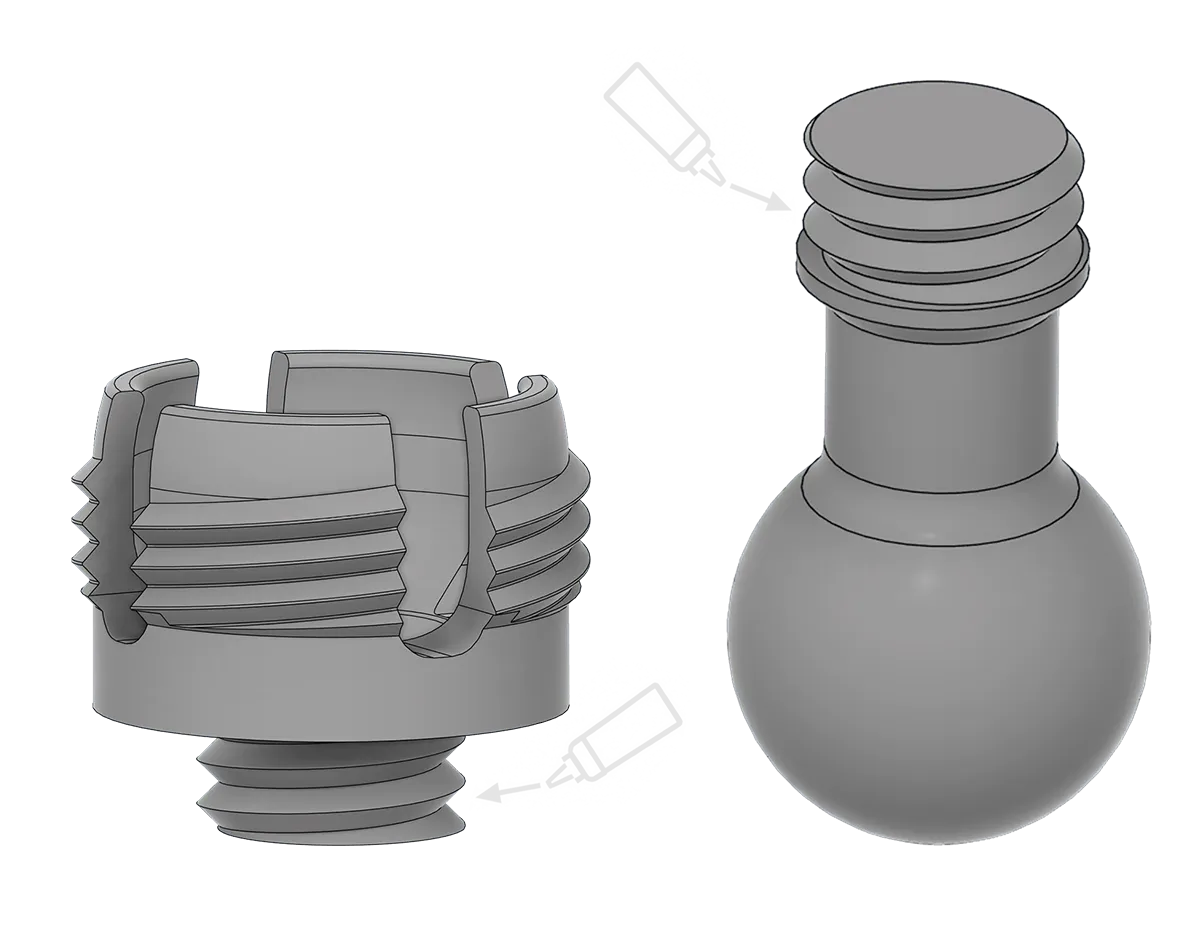
- Always keep an LT-nut on the socket, even when not in use, to protect the fins from accidental damage.
Base
Both the C-stand and X-stand are hollow and must be filled with metal balls, bolts, nuts, small nails, or sand for added weight. After filling, seal the bottom hole with the supplied cap (found in the nuts, bolts, and joints profile). For best surface finish, avoid placing other parts on the print plate.
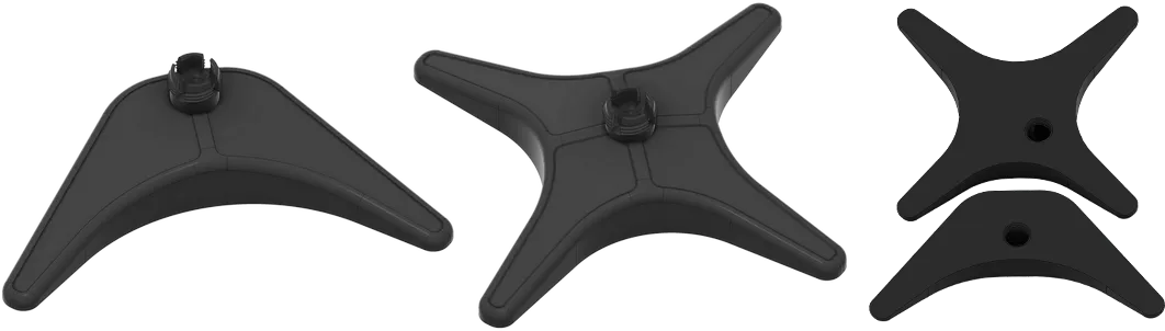
To assemble the table clamp, screw in the long tightening screw until its top is visible. Then, press the round jaw against it until it clicks. Glue a small piece of rubber or thick fabric to the jaws to avoid scratching surfaces. Add a ball socket to the top and/or side of the clamp by applying glue to the threads and screwing it in.
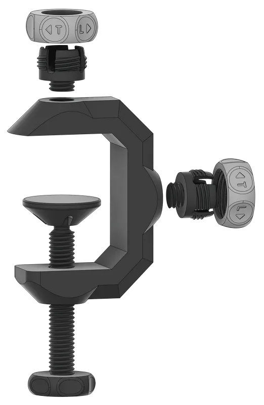
Columns
The columns are made of an inner column and an outer tube, secured using a column nut (found in the nuts, bolts & joints profile). To install it, remove the inner rod, slide the nut up, press the raised lever down, and screw it in fully.
There is an outer brim set, almost fused to the edges. This is to ensure the columns do not fall off during printing. Trim the brim and file the edges at the end.
Top mounts
- The 1/4" top mount (in the nuts, bolts & joints profile), uses a 1/4"-20 UNC, 1" hex socket cap screw. Apply glue at the base of the screw head and halfway along the thread before inserting. Mounts for 7/8" and 1 1/4" length screws are also included in the archive.
- If 1/4" screws are hard to source, an included top mount with a plastic thread and M3x20 support screw can be used, but it’s not as tough. To improve reliability, apply epoxy along the entire M3 screw before insertion and avoid overtightening during use.
- The 3/8" top mount also uses an M3x20 screw and requires the same care.
- The supplied wide nut will prevent top mounts from loosening during use. For a better grip, consider gluing rubber gasket or thick fabric to the nut’s top side.
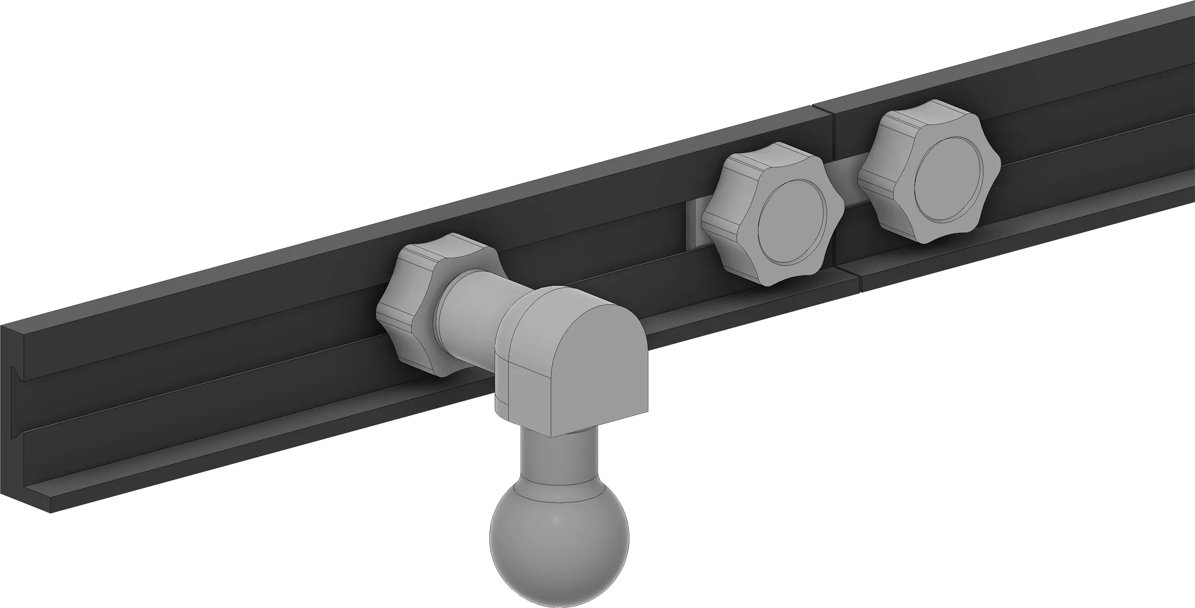
- The included backdrop rail comes in 2 lengths - 150 mm and 220 mm—but you can scale the length as needed. To attach it to a column, use a rail joint with a ball screw—apply glue to the threads before insertion. To connect two rails, use the provided rail-to-rail joint along with two small rail nuts.
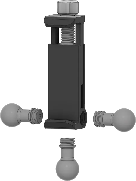
- The phone holder accepts a Ball screw from below or the sides for vertical or horizontal use.
Specialized Attachments and accessories
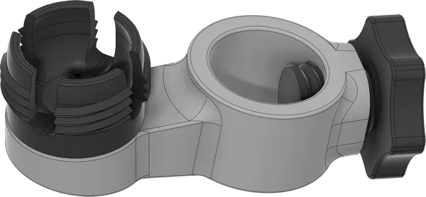
The A-joint uses a ball socket (from nuts, bolts & joints profile). Apply glue to the bottom threads before screwing it in.
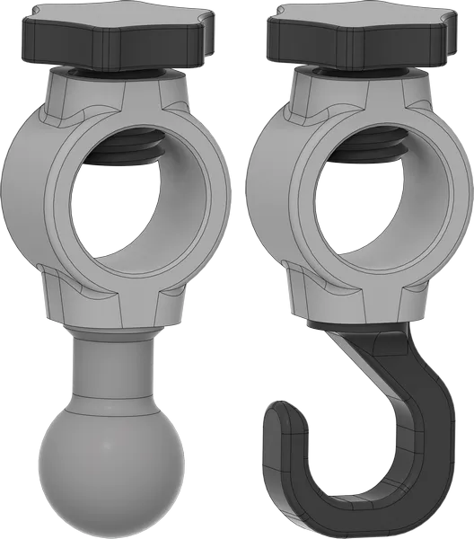
The 2-way and optional 3-way joints are assembled in two configurations: with a Ball screw and a tightening bolt or with a hook and a tightening bolt. Apply glue to the threads of the Ball screw or the hook before screwing them in.
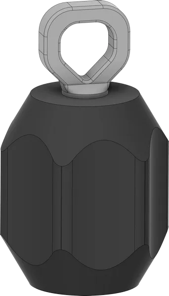
The counterweight can be printed in PLA if desired and should be filled with metal balls, nuts, bolts, or sand before sealing it with the counterweight eye. Apply glue to the threads to keep it securely in place.
Usage
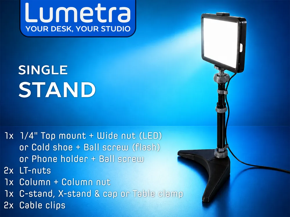
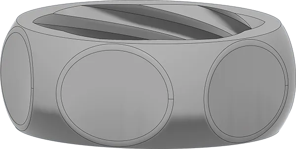
Lumetra’s ball joints enable very easy positioning and adjustment. To secure a ball ended component into a socket, an LT-nut (loosen–tighten nut) is used.
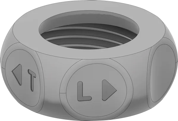
Place the nut on top of the socket but do not screw yet, then push in the component’s ball end into the socket. Finally, tighten the LT-nut. To adjust tilt or rotation, apply force until the desired position is reached, no need to loosen the nut. To disassemble a joint, unscrew the LT-nut and pull out or tilt the ball end until it pops out. If the LT-nut is overtightened and cannot be loosened manually, use the provided LT-wrench to assist in loosening it.
The columns are extendable, with three sizes provided: 100–130 mm, 150–230 mm, and 200–330 mm. To adjust height, loosen the locking nut, move the inner column, then tighten the nut back. Use an LT-nut to attach mounts on top and to connect columns to a base.
The table clamp allows you to attach columns or gear directly (via a top mount) to various surfaces, such as tables, desks, doors, or window frames.
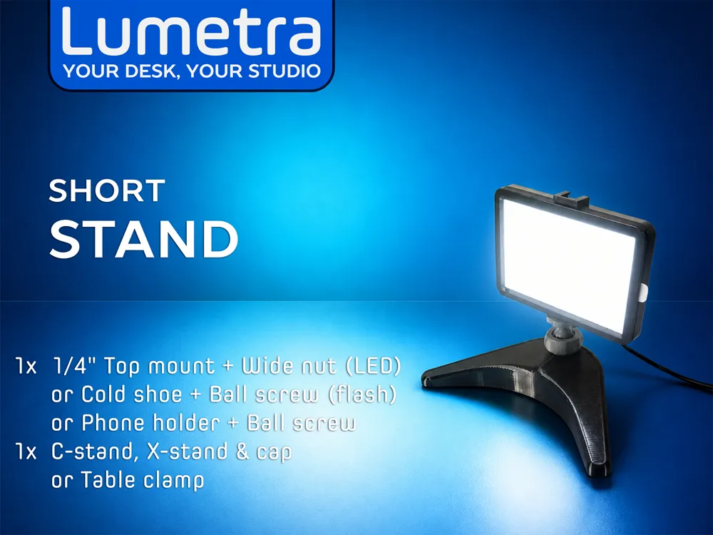
To support the columns, use the provided C-stand and X-stands.
The C-stand is compact and ideal for use close to vertical surfaces, while the X-stand offers greater stability in all directions, making it suitable for heavier equipment.
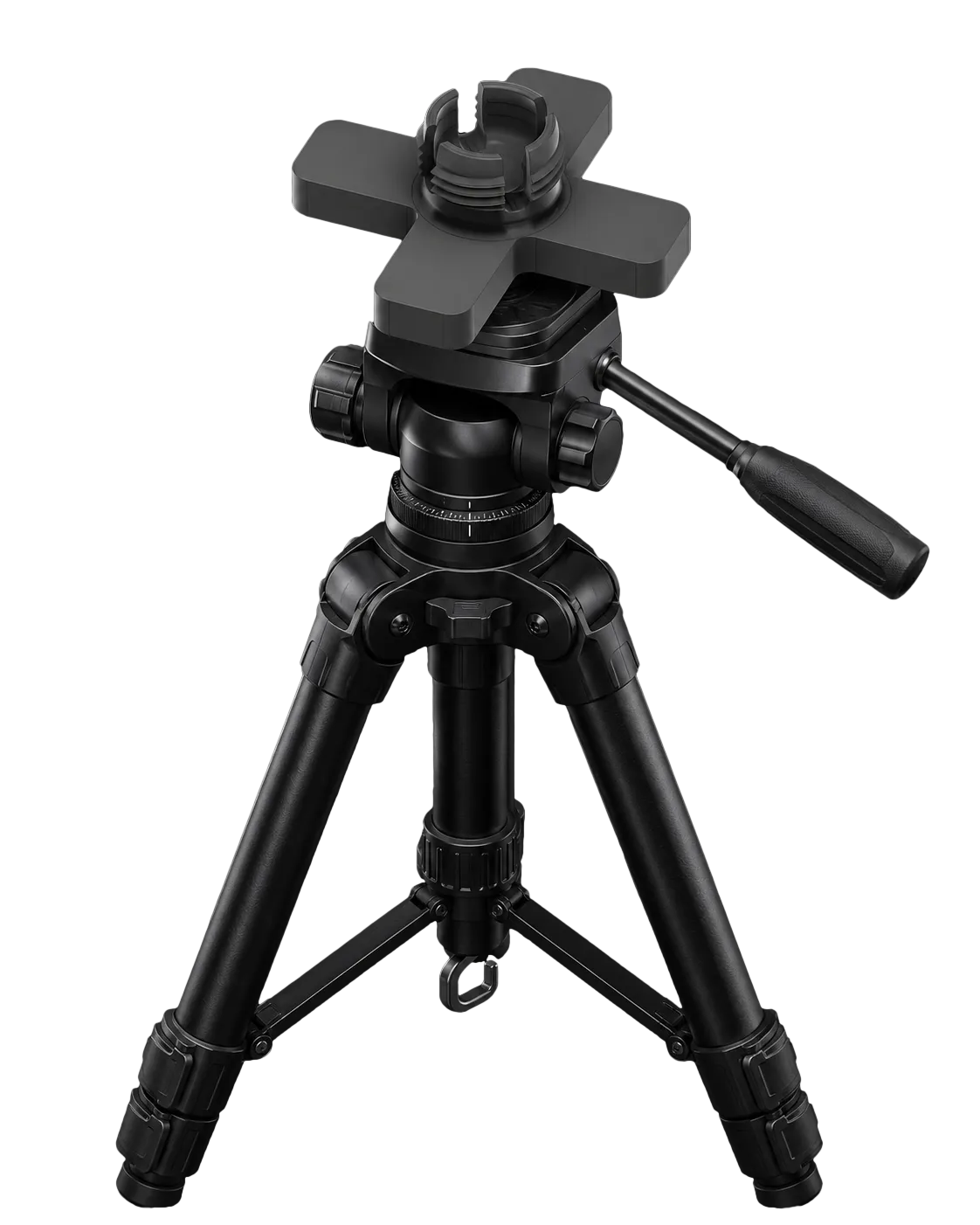
The system can also be mounted on a photographic tripod using the included tripod mount adapter, which features a 1/4" threaded hole on the bottom and a ball socket on top (the model is in the nuts, bolts and joints profile).
An A-joint is used to attach a second column alongside an existing one and tilt it between -15° and +35°, allowing it to:
- Mount a camera or smartphone behind or in front of a light
- Hold color filter or diffusers on a rail in front of a light
- Add another light at a different height, but on the same column
An additional A-joint with 0° – 50° tilt range is also included in the STL/CAD Files section.
The 2-way joint, in combination with a Ball screw, enables perpendicular attachment of a secondary column. For overhead configurations, another copy of the joint can be assembled with a hook to support a counterweight for load balancing.
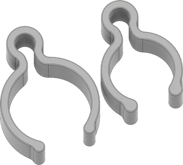
The included Background rail attaches to columns with Rail-to-Ball screw joint and a small Rail nut (all located in the nuts, bolts & joints profile). Connect multiple rails for extended length with the supplied Rail-to-Rail joint. Attach backdrops, diffusers, or color filters to the rail with binder clips.
Two sizes of cable clips are available to secure equipment cables along the column tubes or upper columns.
When taking photos with a mounted phone or camera, use a remote shutter to avoid shaking.
If you have any ideas for new attachments or components for Lumetra, feel free to share them with me — I’ll do my best to design them. A STEP file of the internal and external joint threads is also included to help you create your own parts.
Boost Me (for free)
This photo stand took 8 weeks and 3 kg of filament (and counting) to develop, and it's now used daily for professional product shoots.
I’m happy to share all the files for free — feel free to print, use, and enjoy them for non-commercial purposes. If you like Lumetra, a like, boost, and photos of your prints would mean a lot!
Like the project? Buy me a coffee to keep it growing!
👉 https://coff.ee/sparky.summer
Thank you!
CHANGES AND UPDATES
21/07/25
- The Rail-to-Ball Screw joint (in the nuts&bolts&joints profile) has been updated with a circular tip for mounting the rail at any angle, and an added rear thread for attaching a Ball Screw horizontally. The old design is still available in the STL/CAD files section.
- The C- and X-stands received a minor update. The ball socket has been slightly raised to make it easier to screw in an LT-nut. Additionally, you can now print two C-stands on a single plate without sacrificing wall quality.
01/05/26
- Added non-periscopic Simple columns, to withstand heavier loads. Check them here: https://makerworld.com/en/models/2740334-lumetra-simple-columns#profileId-3038642
License

You shall not share, sub-license, sell, rent, host, transfer, or distribute in any way the digital or 3D printed versions of this object, nor any other derivative work of this object in its digital or physical format (including - but not limited to - remixes of this object, and hosting on other digital platforms). The objects may not be used without permission in any way whatsoever in which you charge money, or collect fees.


Comment & Rating (350)