
A1/A1 mini Cable Management Support
Print Profile(8)



Description
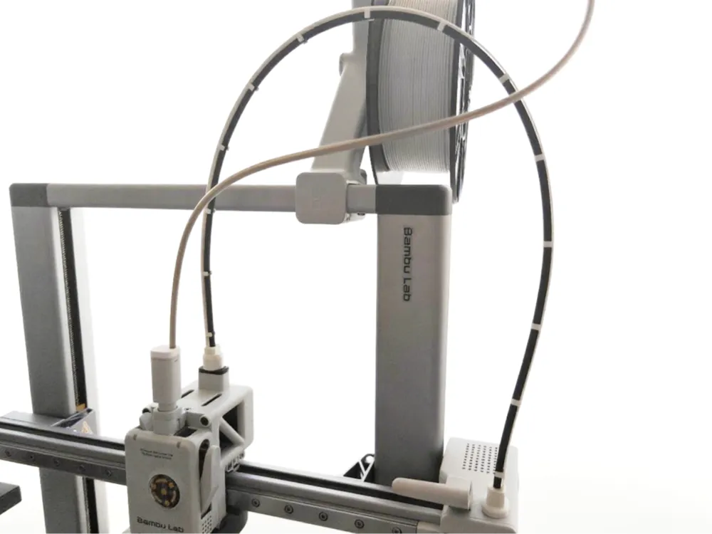
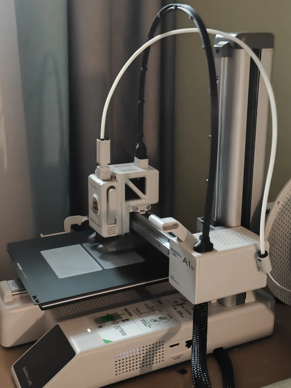
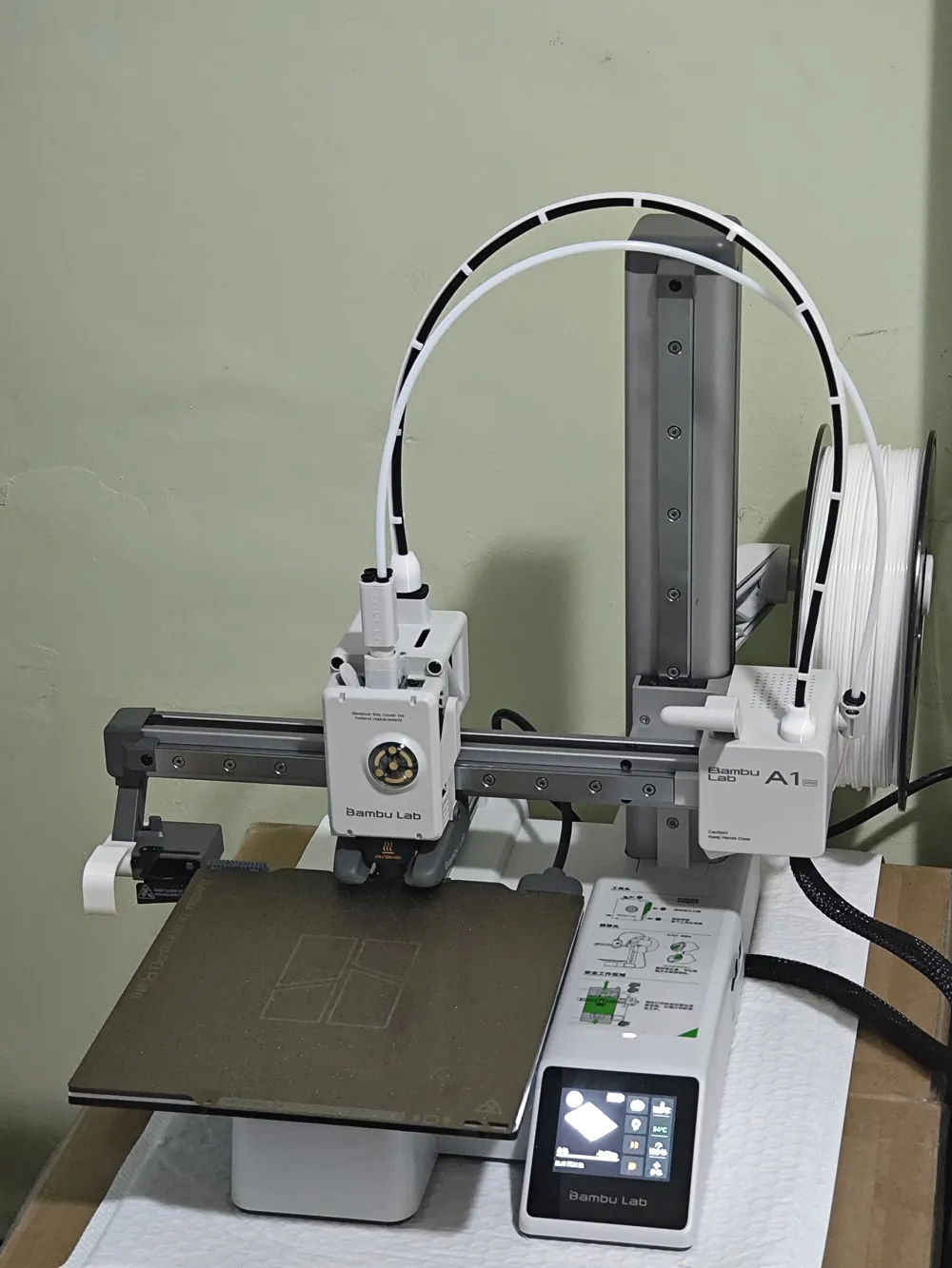
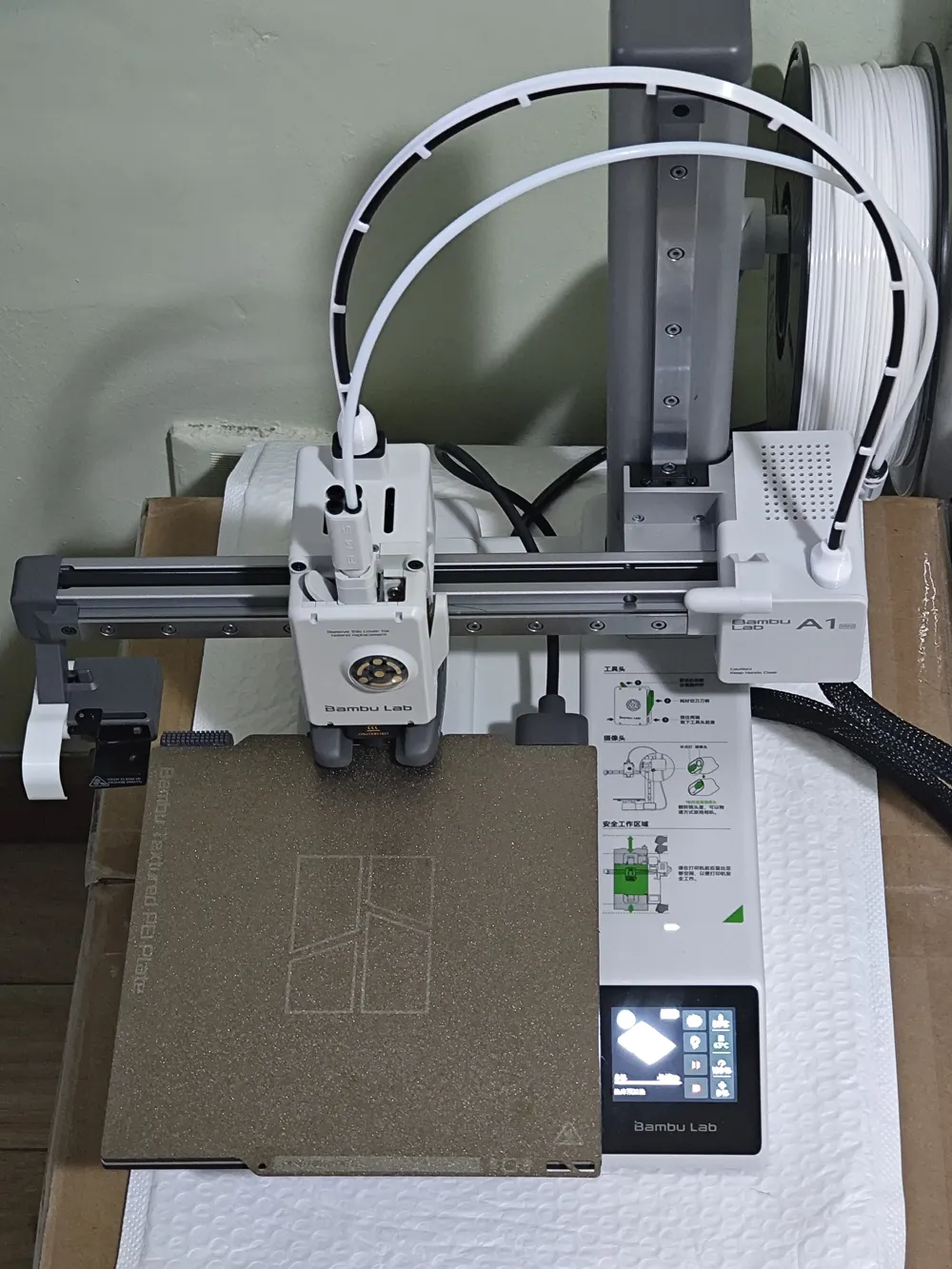
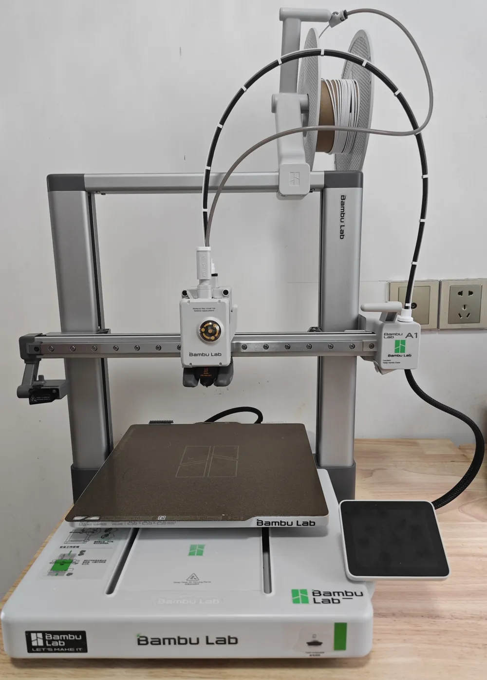
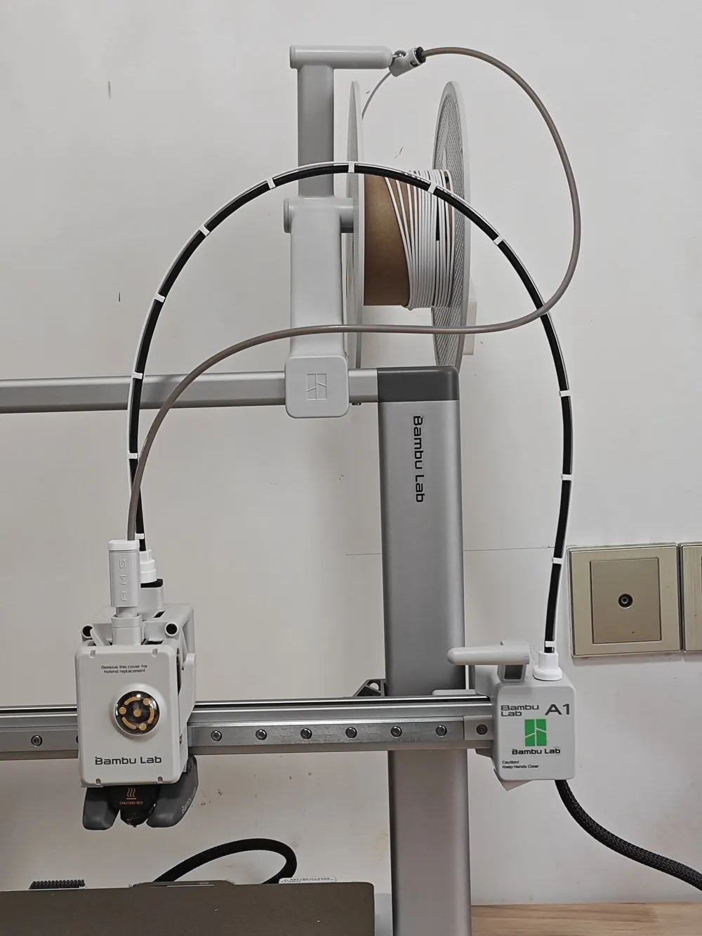
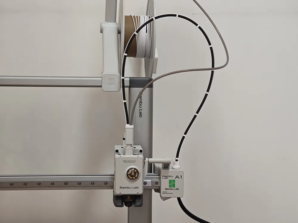
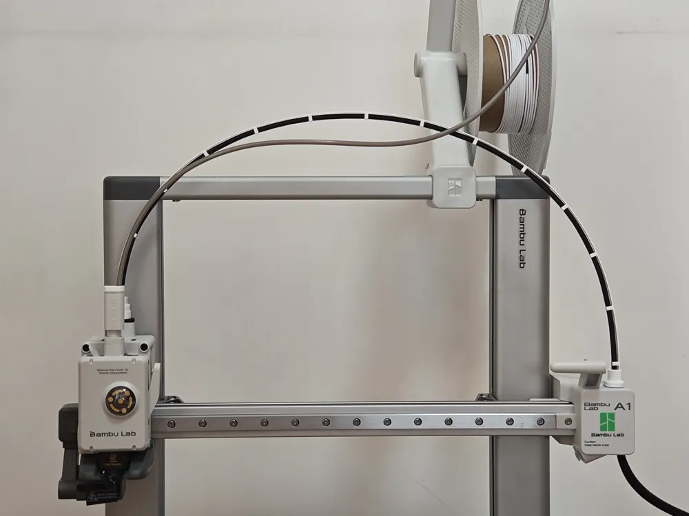
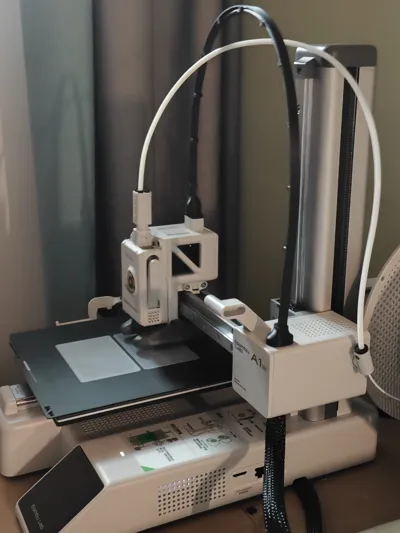
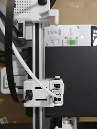
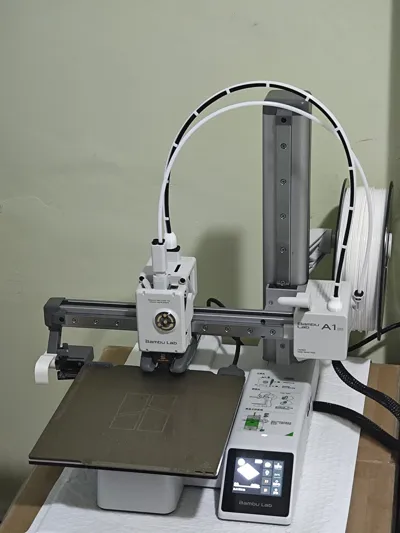
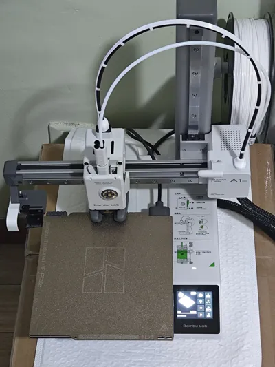
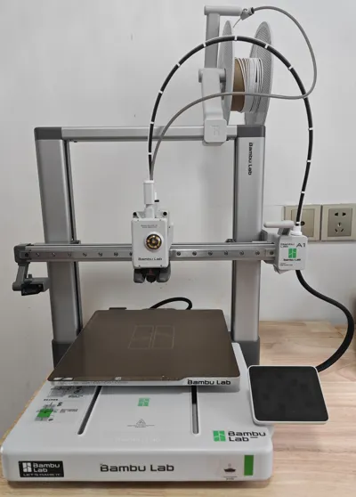
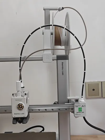
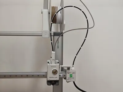
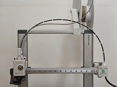
A1/A1mini Cable Management Support
Design Concept
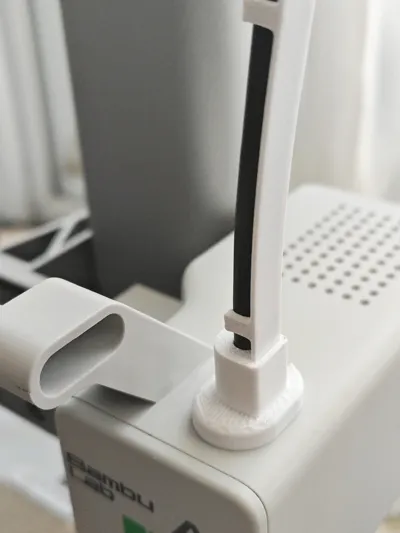
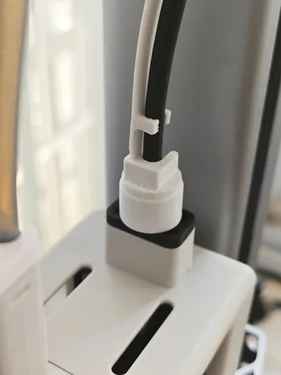
Addressing the shortcomings of existing cable management support models in terms of aesthetics and practicality, I undertook a completely new design. Through precise measurements and multiple iterative tests, I finally created this minimalist style cable management solution specifically designed for the A1/A1mini series
Version Update Log
Update Date | Important Updates |
|---|---|
| 2025-08-02 | Optimized connector opening size, significantly improving installation experience |
| 2025-07-22 | Released A1 lower support version[Download Link] |
| 2025-07-17 | Optimized printing parameters, comprehensively improving surface quality and support effect ⚠️ Note: The support structure is tightly integrated with the model, please exercise caution when removing |
| 2025-07-16 | Optimized buckle dimensions and connector structure, increased brim width to improve adhesion |
| 2025-07-01 | Added A1mini compatible version (thanks to @米隆 @cloud for testing support) 📌The left and right connectors are universal with the A1 version |
| 2025-06-28 | Enhanced connector structural strength, improving installation stability |
Specifications
| Parameter | A1 Version | A1mini Version |
|---|---|---|
| Total support strap length | 666mm | 550mm |
| Support strap thickness | 1.0mm | 1.0mm |
| Support strap width | 7.0mm | 7.0mm |
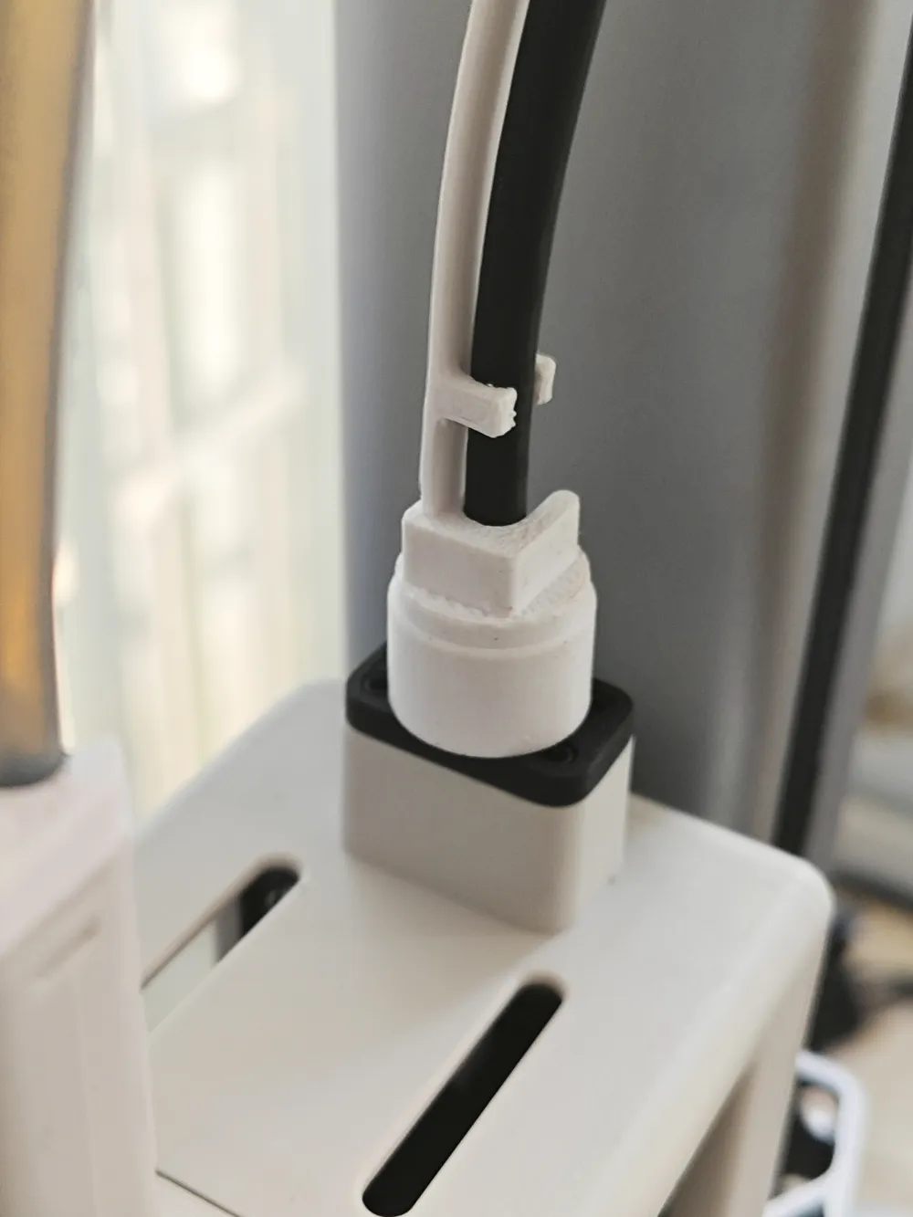
| Connector groove size | 7.1×1×5mm | 7.1×1×5mm |
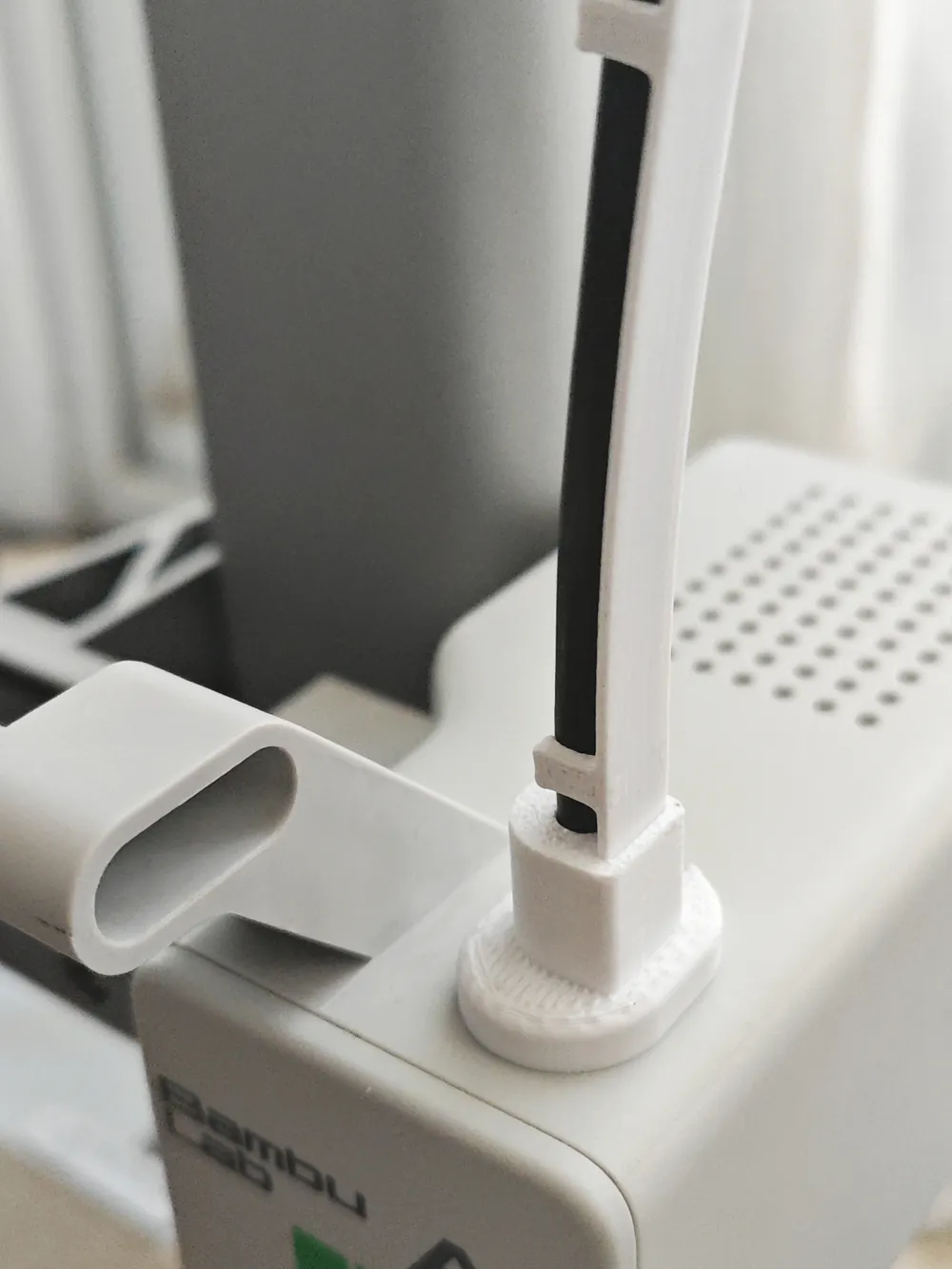
| Left connector height | 16.4mm | 16.4mm |
| Right connector height | 13.6mm | 13.6mm |
Product Advantages
- ✨ Ultra-lightweight: Extremely light, barely affecting equipment motion performance
- 🎨 Minimalist Aesthetics: Compact size, seamlessly integrating into the overall equipment design
- 🔒 Reliable Fastening: Buckle design ensures stable and secure cable management
- 💰 Economical and Energy-saving: Minimal filament required, clear advantage in printing costs
- 🛡️ Durable: Flexible structural design, excellent fatigue resistance
Printing Guide
Support Strategy
- One-piece printing: Uses inverted external supports, easy to remove and smooth inside
- Split printing: Achieves a better appearance
Material Selection
- [Recommended] PETG: Excellent durability and flexibility
- [Optional] PLA: Be aware of environmental humidity and long-term brittleness issues
- [Required] Pre-treatment: Ensure the build plate is clean and the material is dry
Parameter Suggestions
- Layer height: 0.12mm (better surface quality)
- Adhesion: Enable brim function (prevents warping)
- Temperature: Adjust according to filament characteristics
🛠️ Installation Guide
1. Preparation and Post-processing
- Visual Inspection: Check that the model's appearance is intact and that there are no residues in the connector groove
- Sanding Treatment: Check for any print residues or burrs on the support strap. If necessary, use sandpaper or similar tools for light sanding to ensure a smooth and unobstructed surface
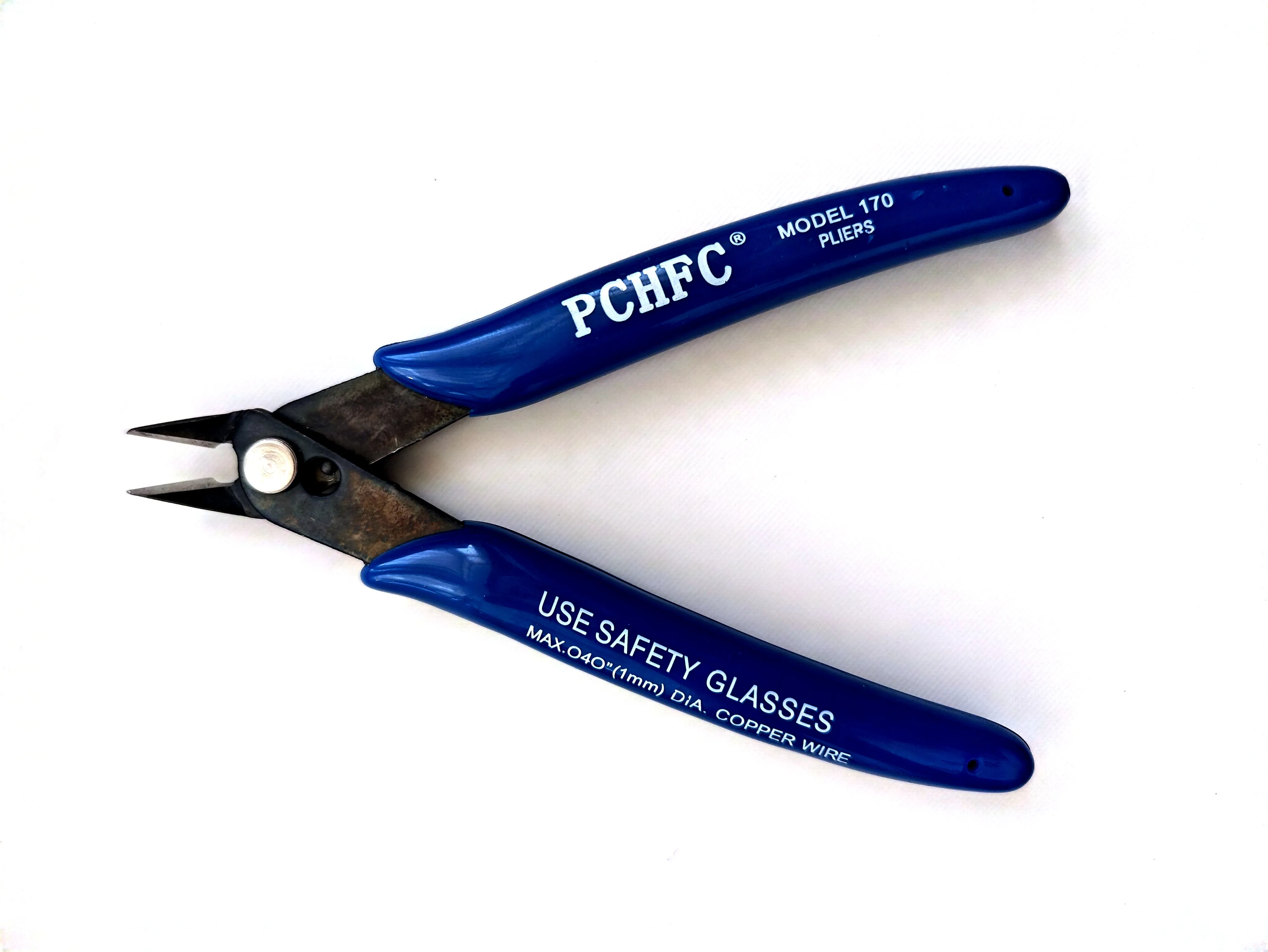
- Support Removal: After printing, please wait for the model to cool completely to room temperature, then carefully remove all supports using flush cutters or similar tools
2. Installation Steps
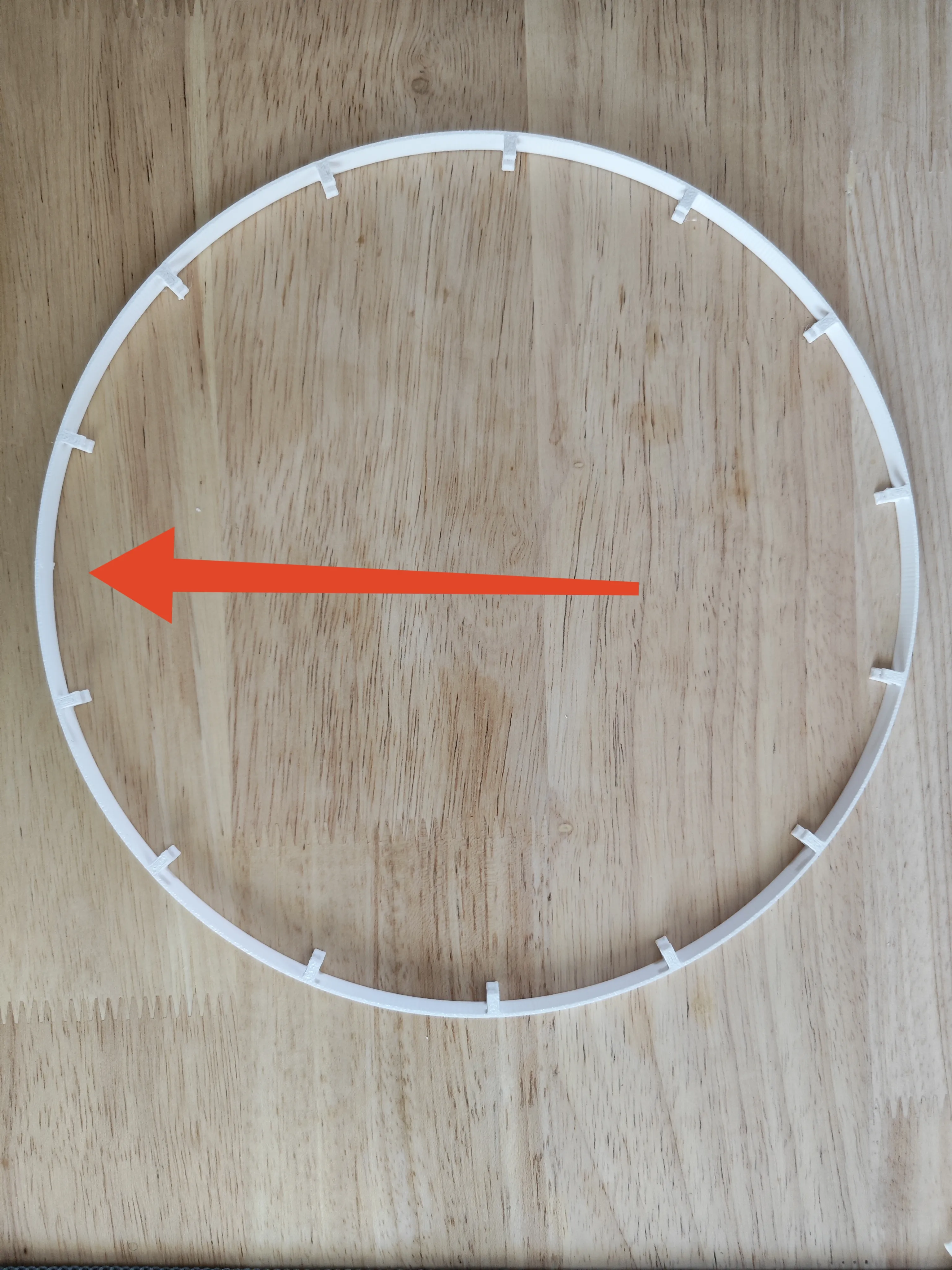
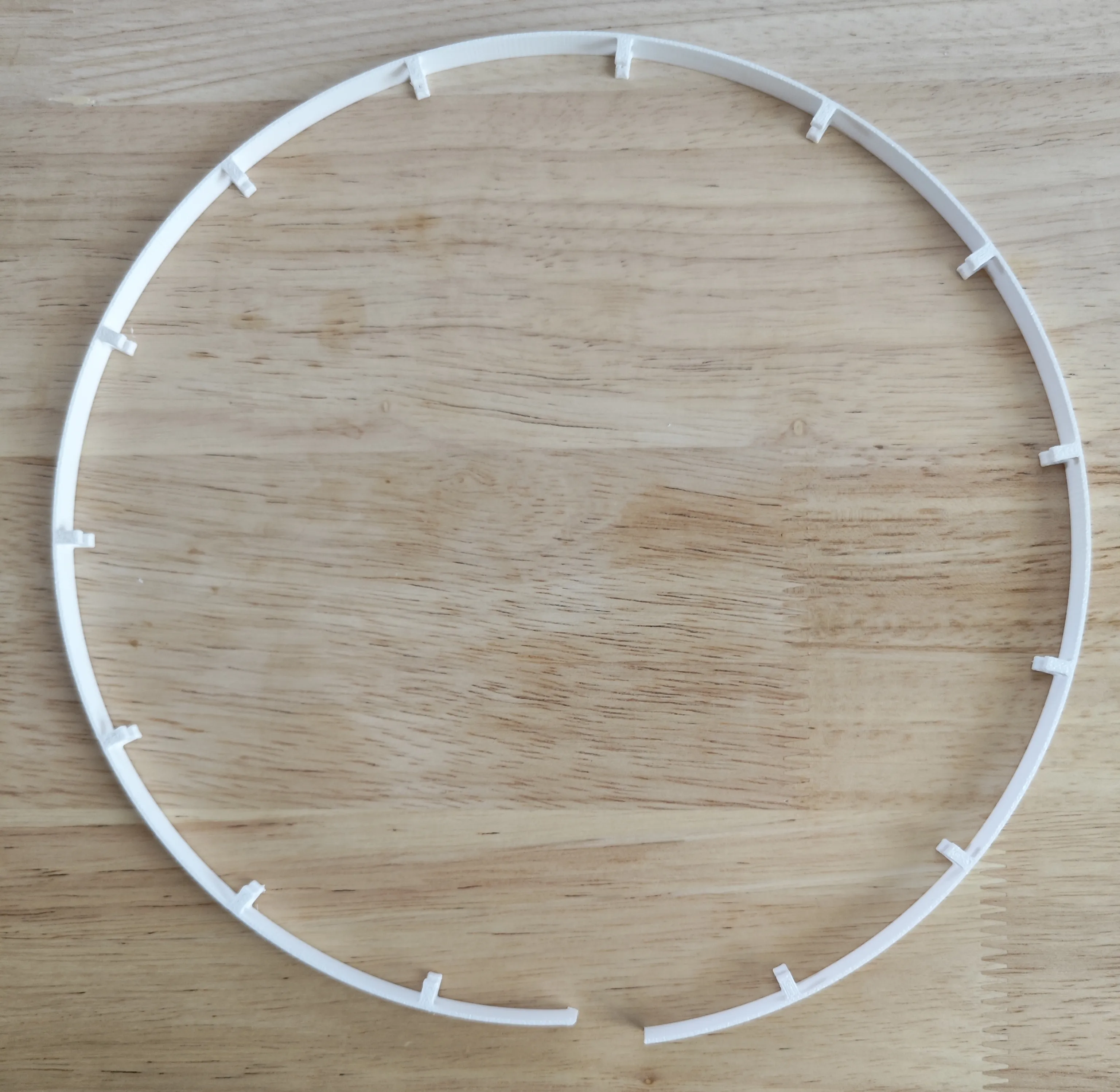
Step One: Cut the main body of the cable tie strap
- Locate the widest section of the cable management support strap
Cut it along its middle seam (Z-axis seam preset position) into two parts
Step Two: Install the left (printhead side) connector
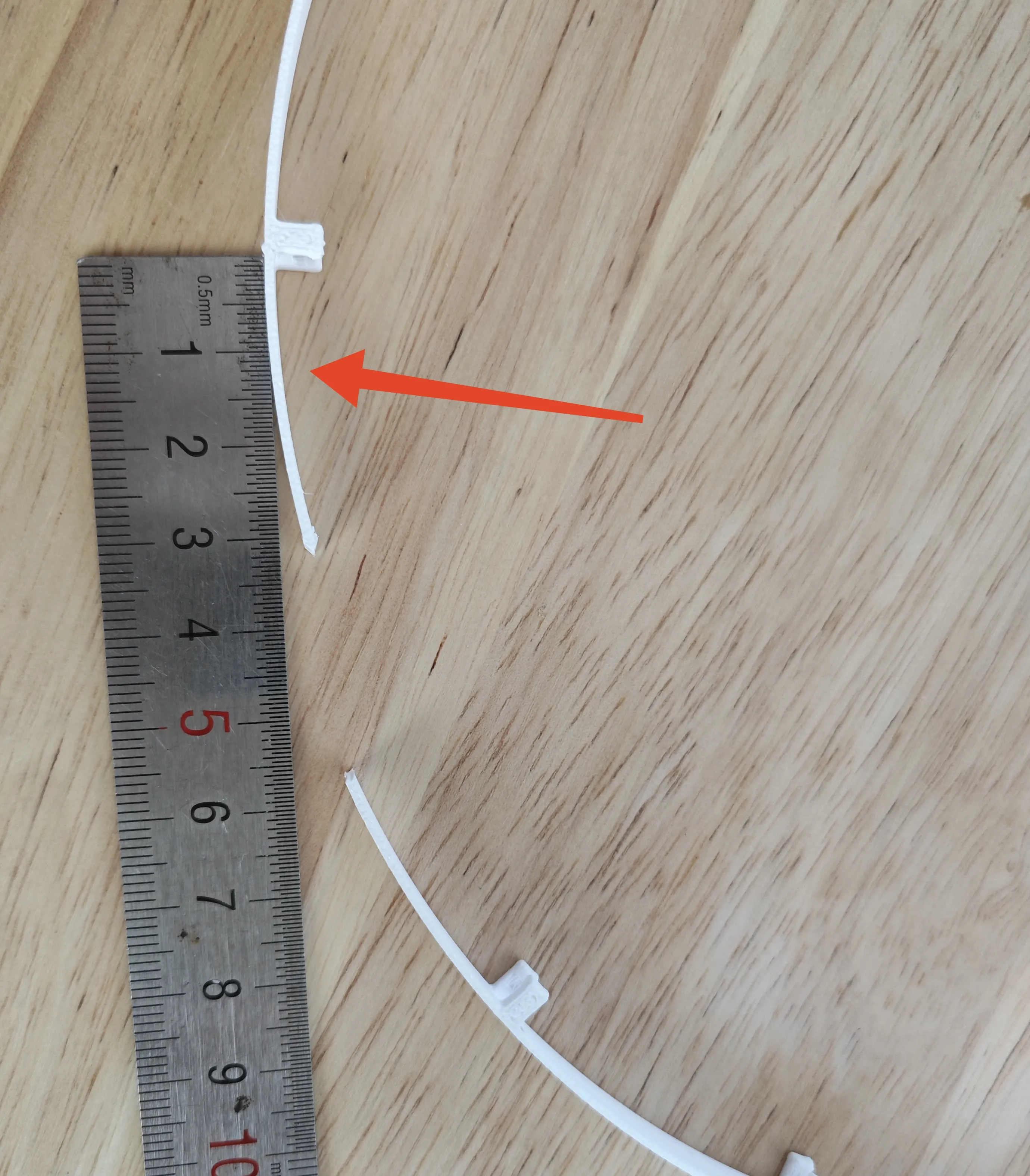
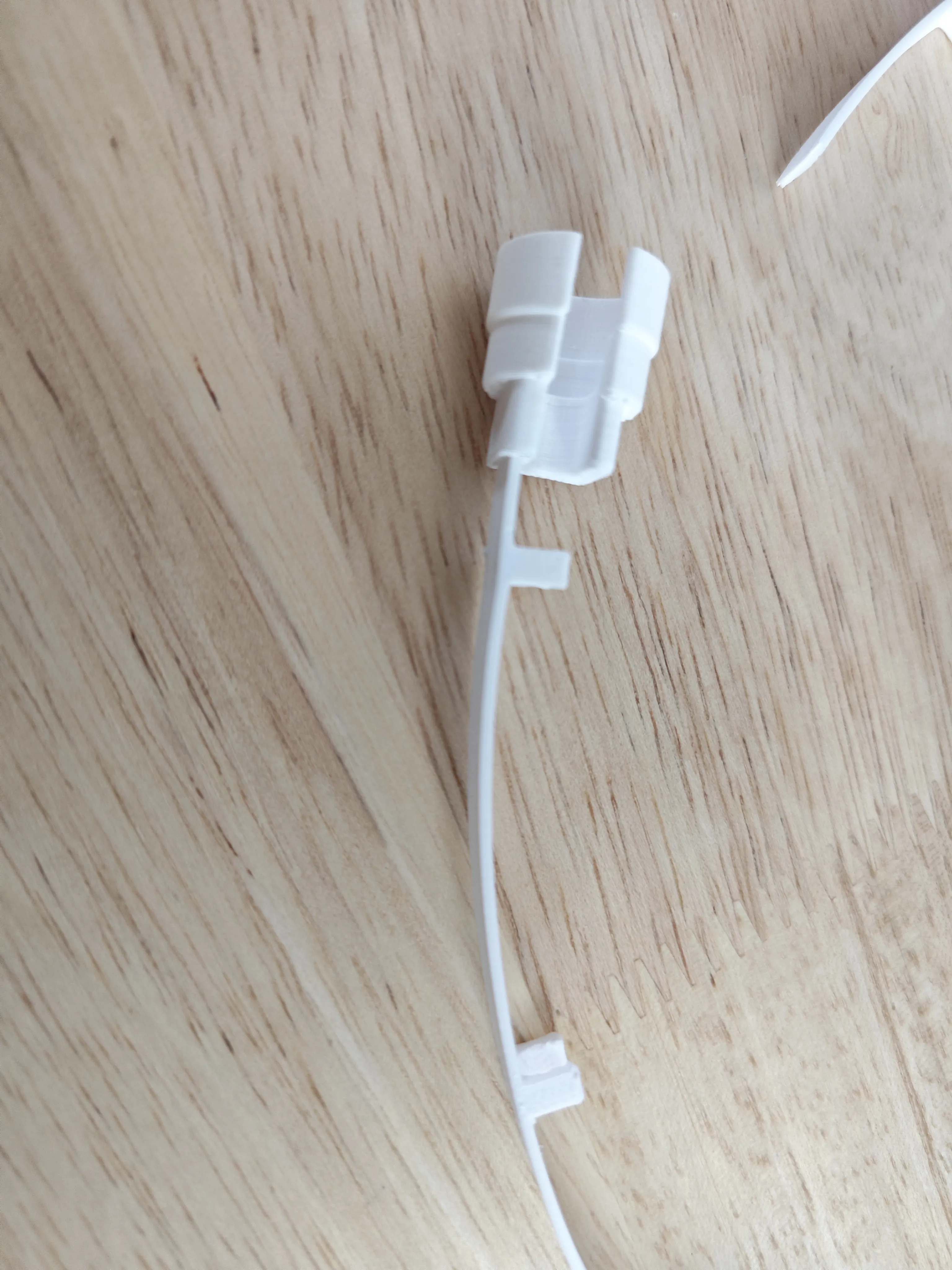
- Pre-cut: Cut the part of the trimmed cable management support strap (the end for the printhead side) near the connector to about 12mm-20mm (you can install and compare the length first, then cut, depending on the actual situation)
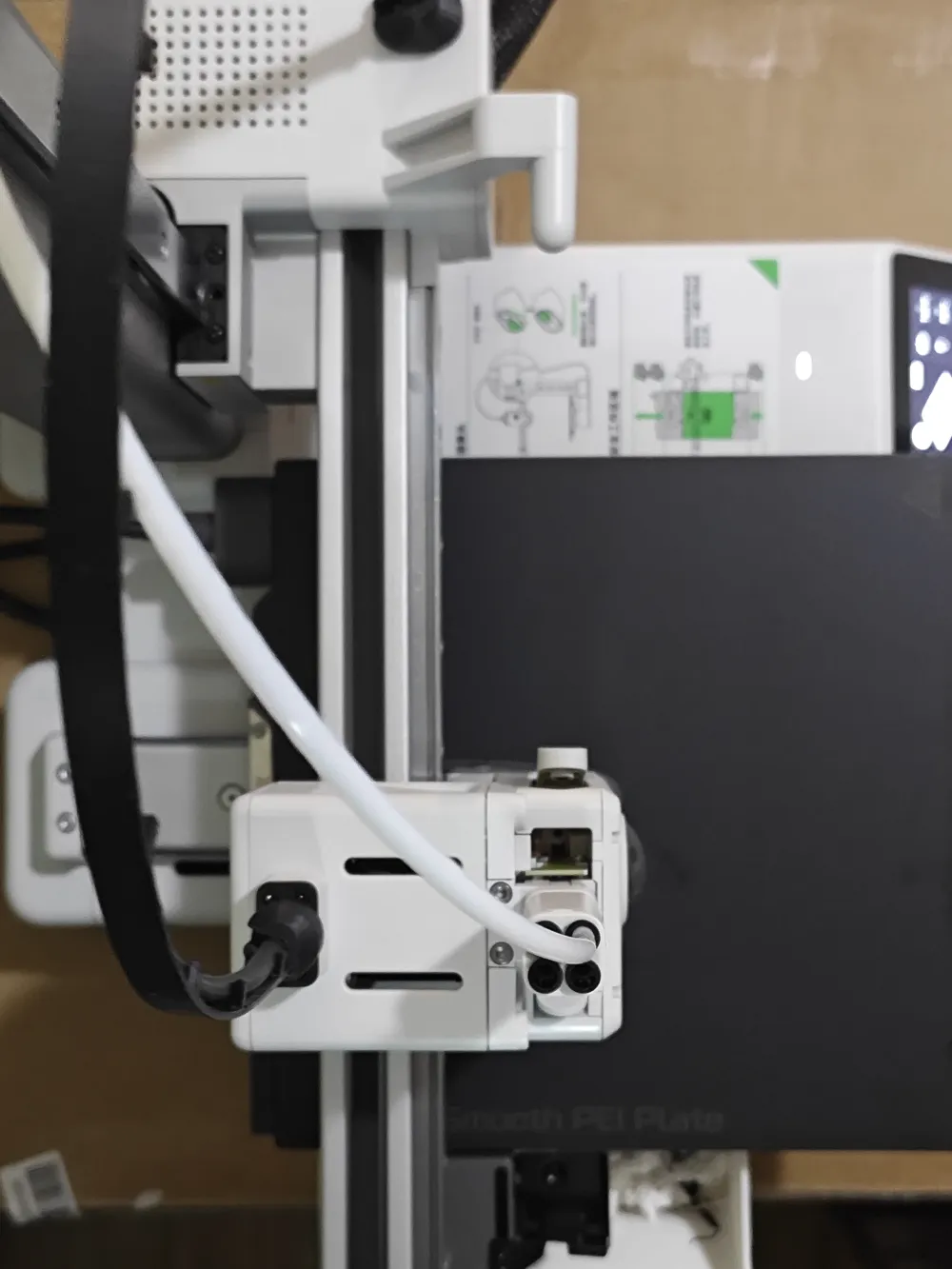
- Confirm Direction: Ensure the connector's opening faces the back of the printer
Pre-assembly: First assemble this connector with the cable management support strap before installing it onto the cable. Note: If it cannot be inserted smoothly, lightly sand the end of the cable management support strap until it can be easily installed
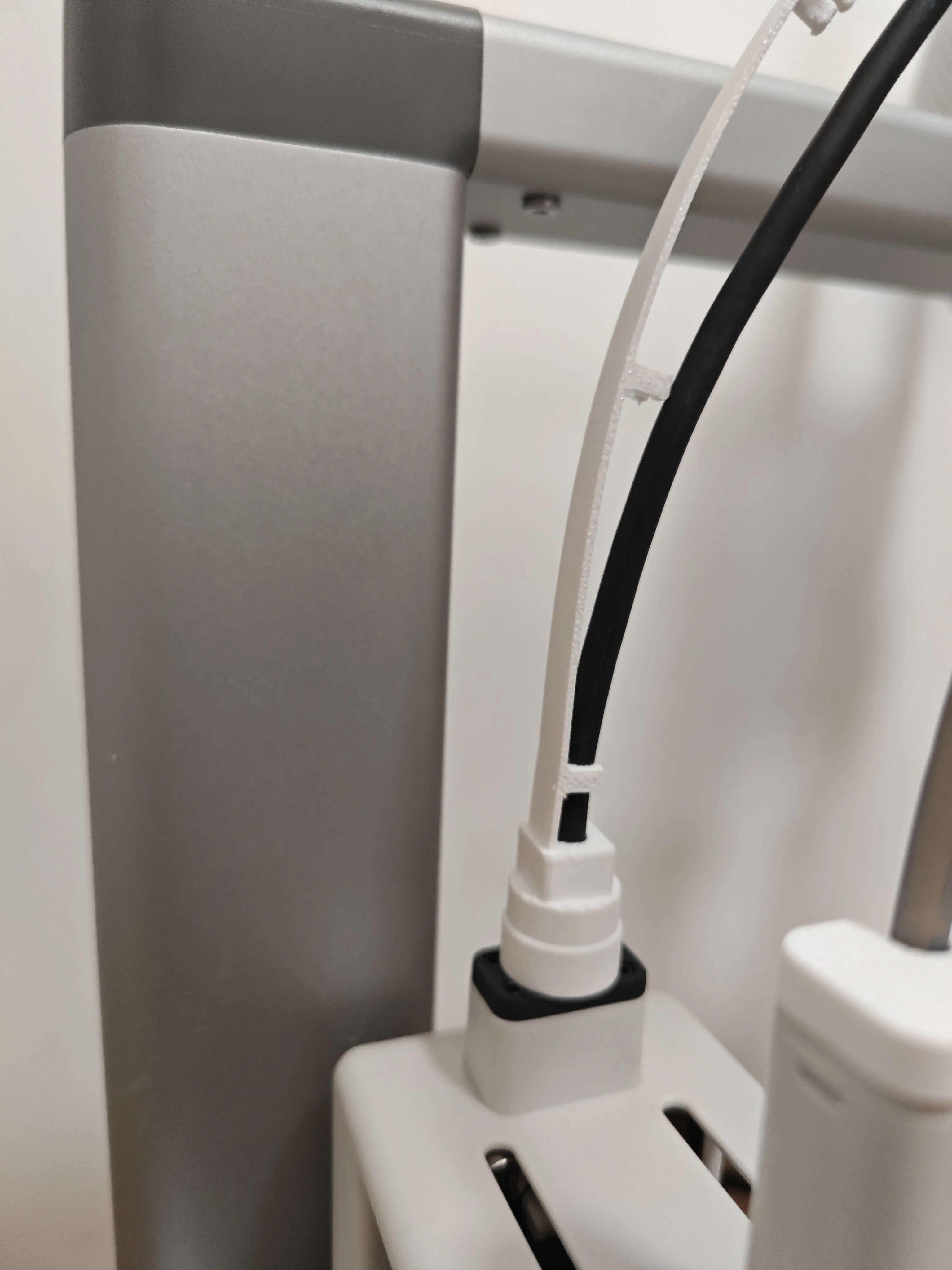
Step Three: Secure the cable
- Along the cable's path, fasten all buckles of the installed cable management support strap one by one
- Key: Do not fasten the last buckle yet to allow for later length adjustment
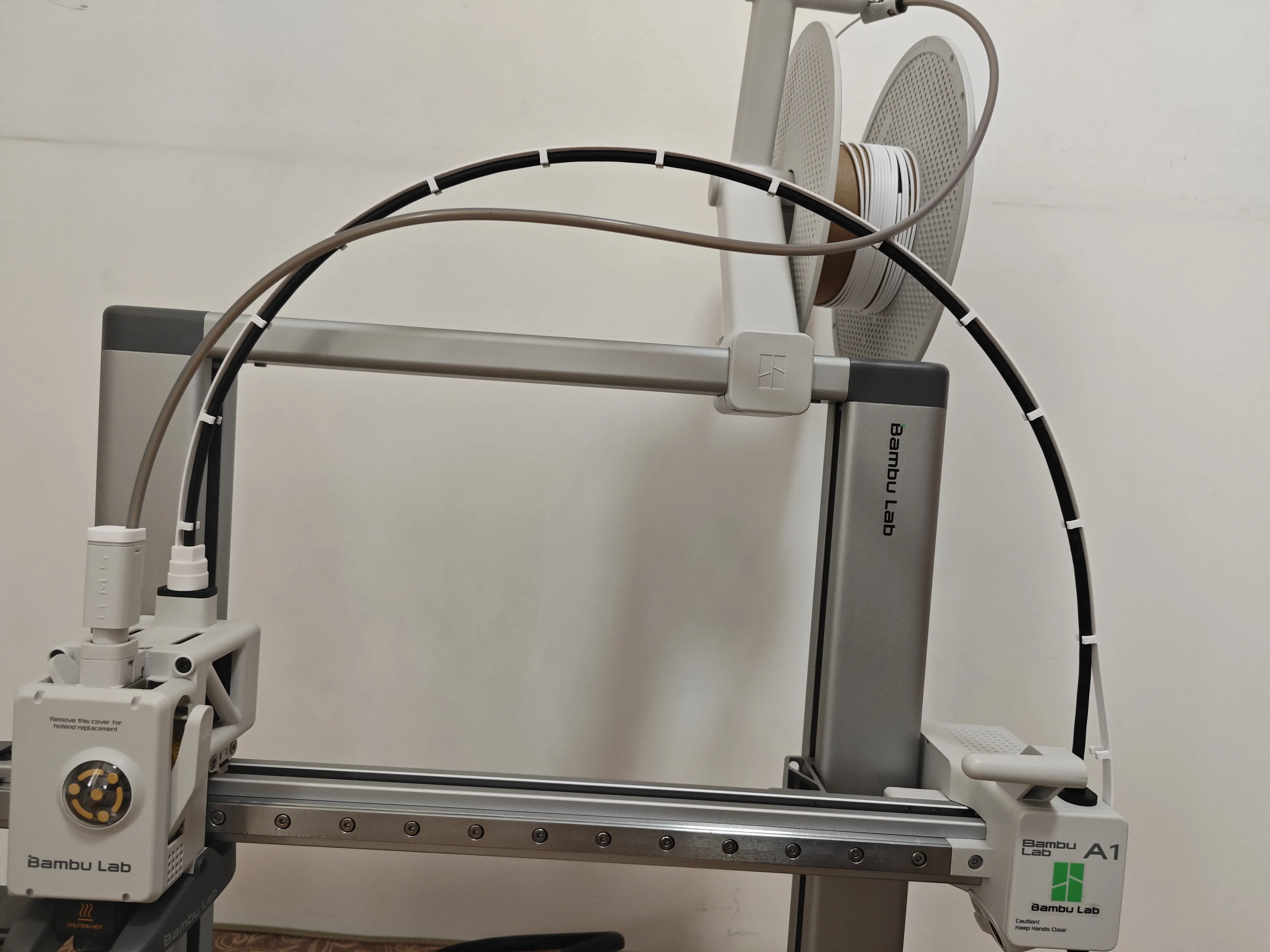
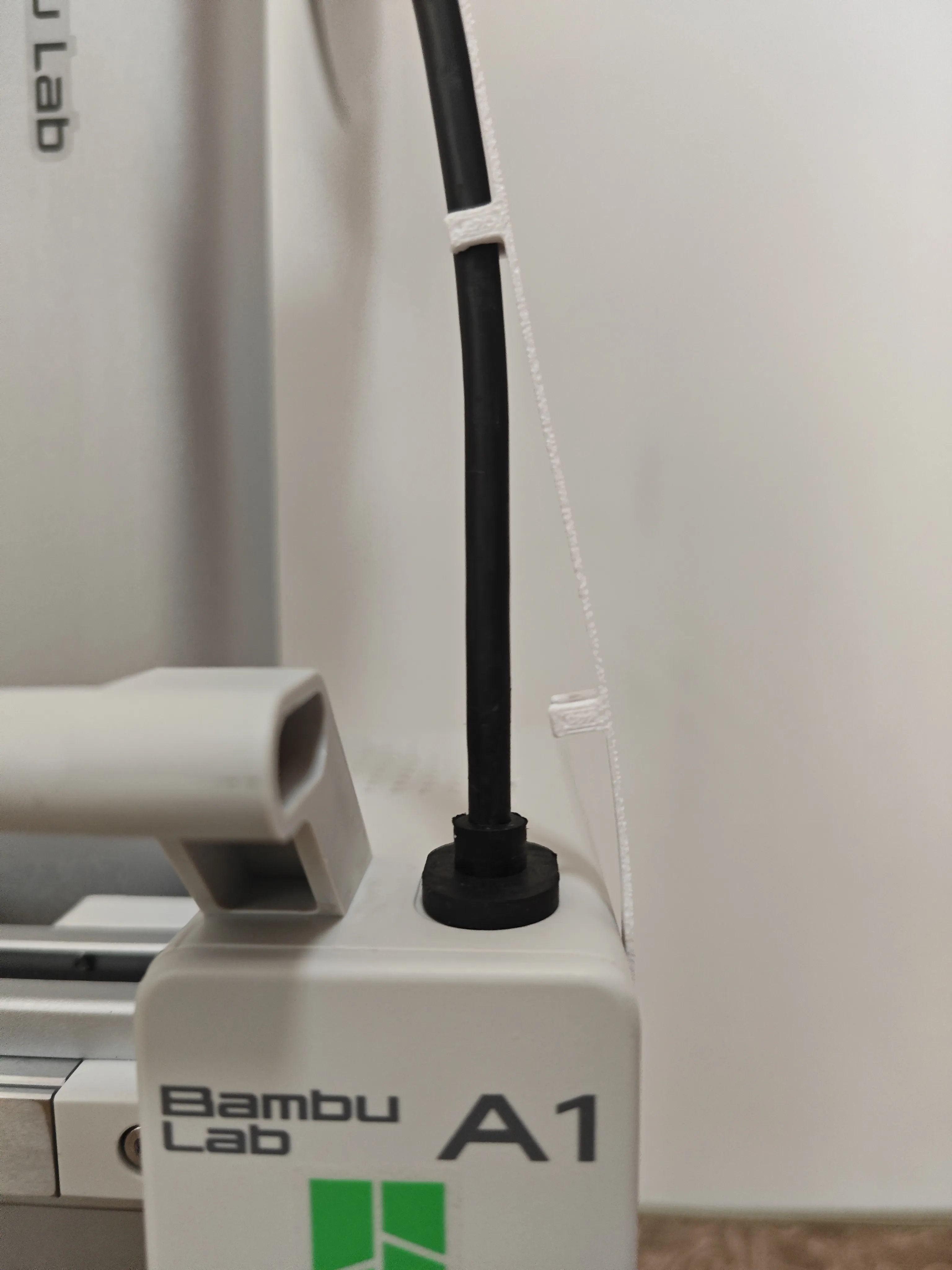
Step Four: Install the right connector and finally secure
- Install the other end: Install the connector at the other end of the cable management support strap to the right side of the printer, also ensuring its opening faces backward
- Determine Length: Straighten the cable and determine the appropriate length for the cable management support strap, ensuring the cable is naturally relaxed and not too tight or too loose
- Cut and Install: After cutting off the excess length, insert the right connector into its 5mm deep mounting slot to secure it
- Complete Installation: Finally, fasten the last buckle that was left unfastened earlier to complete the entire installation
- Adjust the cable tie: After installation, if the cable management support strap's curvature is not smooth enough, you can manually adjust the curve to optimize the cable's arc
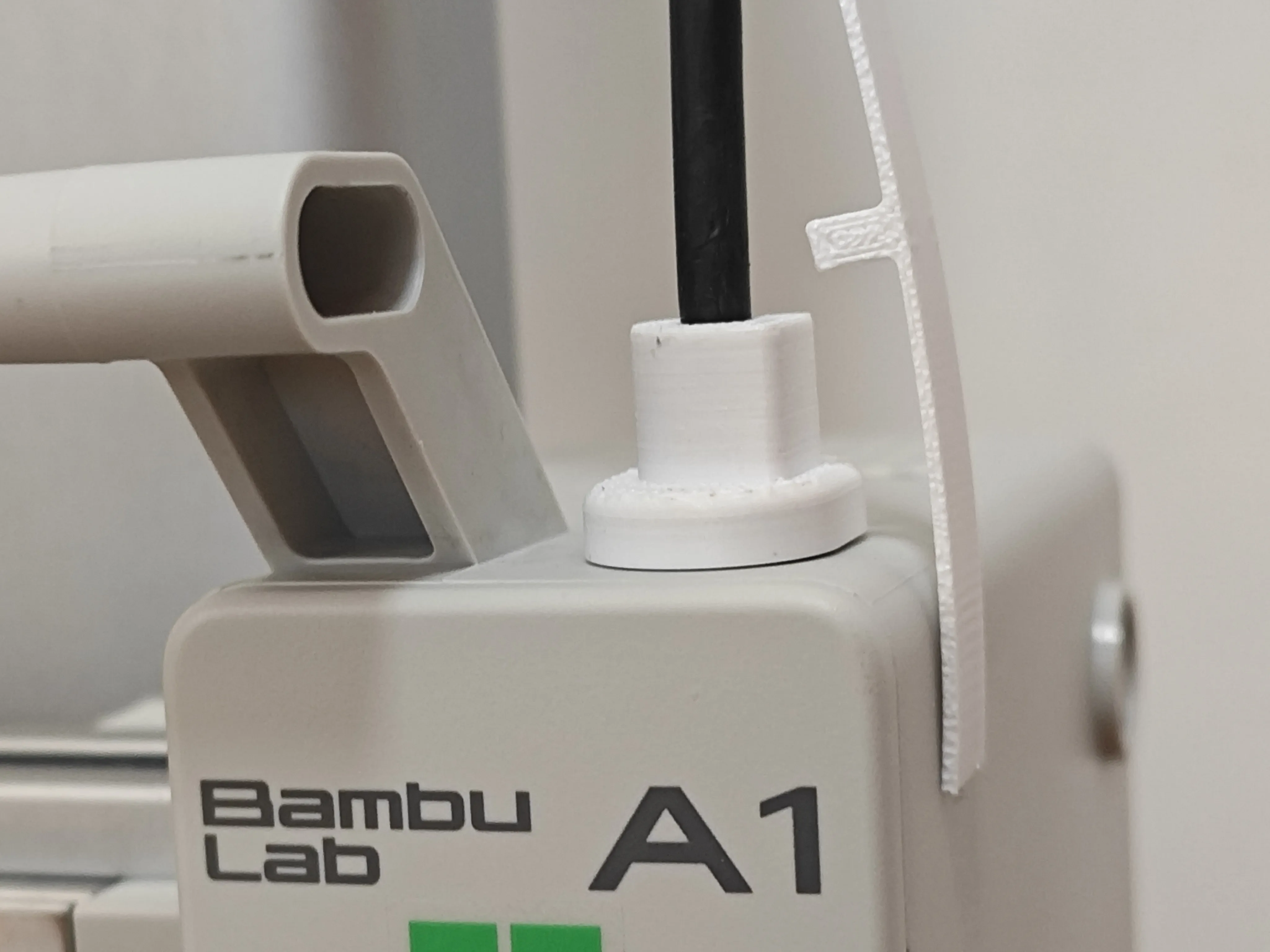
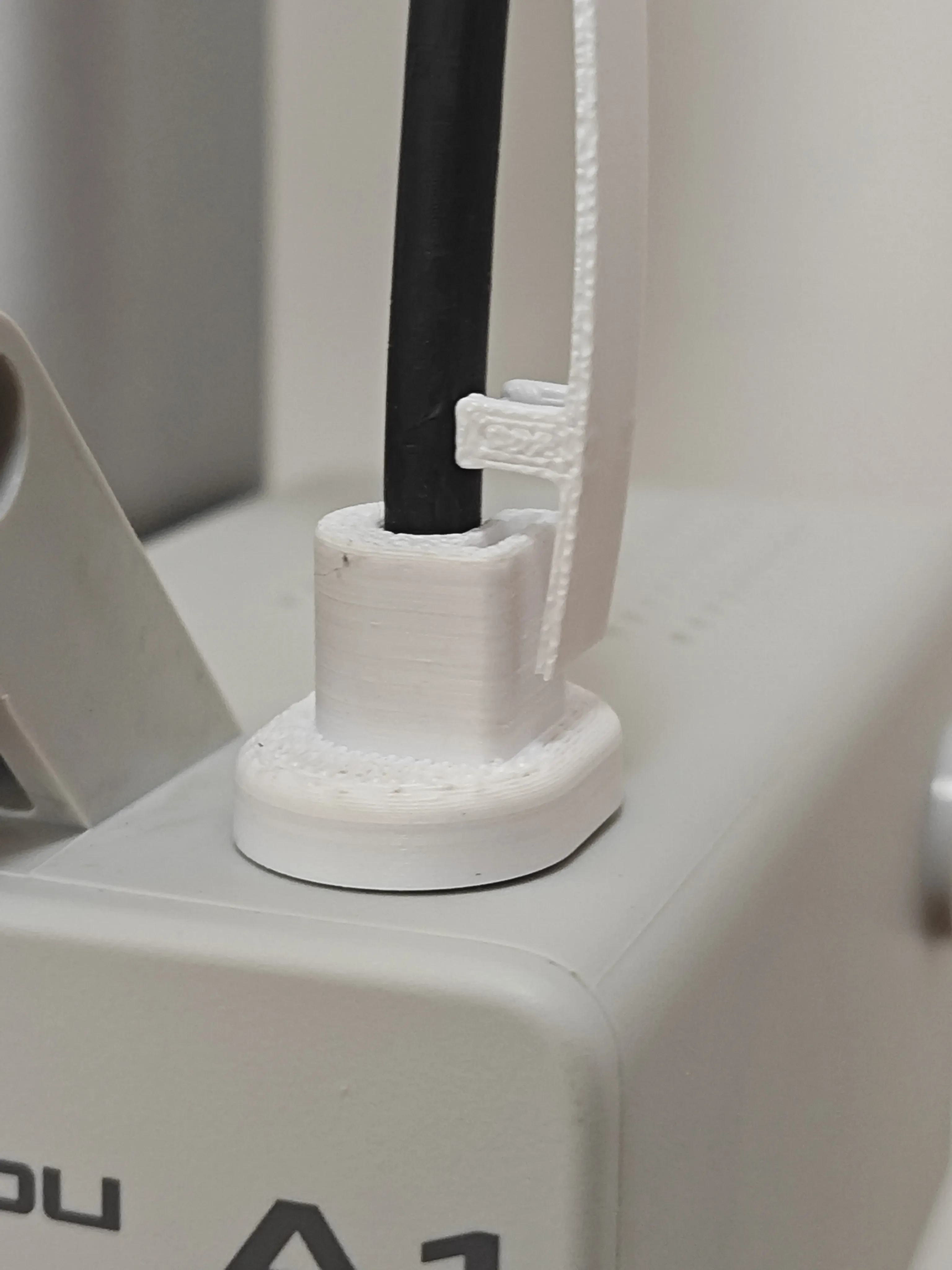
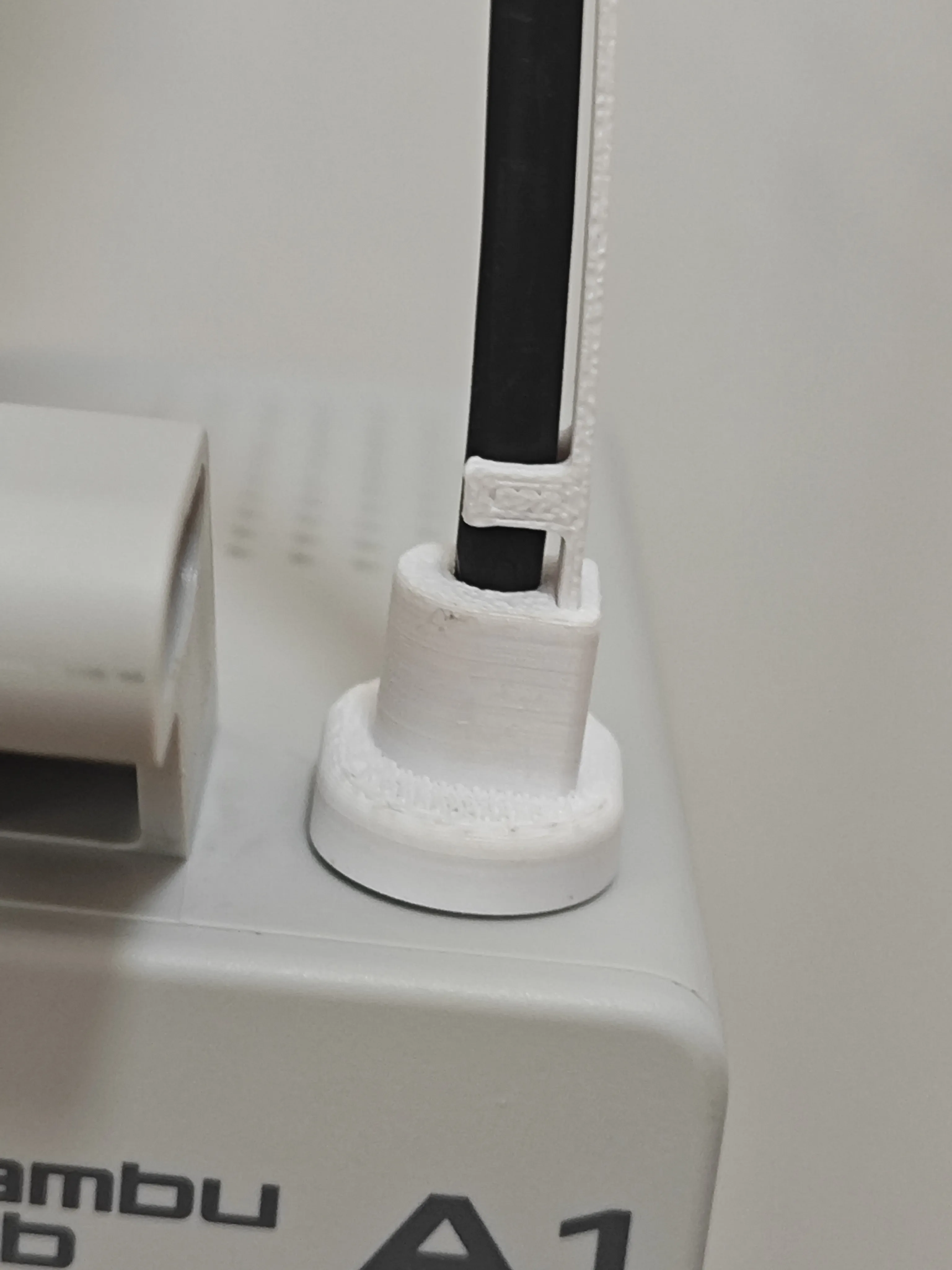
Warm Reminder: During operation, do not forcibly bend the cable or use excessive force. Ensure all buckles and connectors are properly seated to avoid affecting the normal movement of the printhead
❓ Frequently Asked Questions
Q1: What if the support structure is difficult to remove?
A: Ensure the model is completely cool, and carefully pry it open from the gaps using flush cutters or similar tools. Cooler materials become more brittle, making them easier to remove
Q2: How to improve difficulty in assembling the connector groove?
A: Ensure the groove is clean and free of residues, and that the print dimensions are accurate. If necessary, lightly sand the end of the cable management support strap or the inside of the groove
Q3: Are there scratches or marks on the cable after installation?
A1: If the buckles are not printed well or supports are not cleanly removed, there might be burrs. Forcibly installing them can damage the cable. It is recommended to clean and deburr any flaws inside the buckles after printing. Slight marks might appear on the cable after installation
Support and Communication
Boost Me (for free)
This project is my second open-source work, and I appreciate the strong support from the community!
If you encounter any issues or have good suggestions, please leave a comment on the project page to discuss. Your feedback will help me continuously improve and jointly promote the perfection and development of the project
License

You shall not share, sub-license, sell, rent, host, transfer, or distribute in any way the digital or 3D printed versions of this object, nor any other derivative work of this object in its digital or physical format (including - but not limited to - remixes of this object, and hosting on other digital platforms). The objects may not be used without permission in any way whatsoever in which you charge money, or collect fees.


Comment & Rating (577)