Big size Flip Clock V1 (WiFi / NTP or RTC Version)


Print Profile(2)


Description
Project : ESP8266 Servo Flip Clock - V1 Prototype (WiFi / NTP Version or RTC Version)
Example Code..
https://github.com/ppfamily99/FlipClock
Boost Me (for free)
Introduction
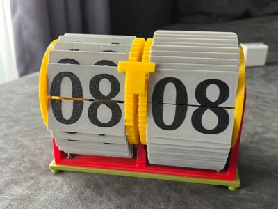
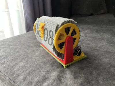
Welcome to the WiFi-enabled version of the 3D Printed Flip Clock project. This variant is a true IoT device, designed for those who prefer a "set it and forget it" experience. By leveraging an internet connection, this clock automatically fetches the precise time and maintains perfect accuracy without any manual intervention. It combines retro mechanics with modern, hands-free smart technology.
Key Features
- Designed for 3D Printing: All primary mechanical components are designed to be printed on a standard FDM 3D printer.
- Servo-Driven Mechanism: Utilizes common and affordable servo motors to drive the hour and minute flap mechanisms.
- Powered by ESP8266: A powerful and popular WiFi-enabled microcontroller at its core.
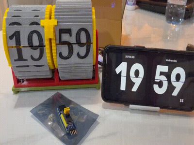
- Automatic Time Sync via NTP: The clock connects to your WiFi and fetches the precise time from internet NTP servers (time.google.com). It automatically adjusts for your timezone, ensuring it's always accurate.
- User-Friendly WiFiManager: No need to hardcode WiFi credentials into the code! On the first boot (or if the connection is lost), the clock creates its own WiFi Access Point. You can simply connect to it with your phone or computer, and a web portal will automatically open, allowing you to scan for and connect to your home WiFi network.
- Precise Feedback System: Employs limit switches to detect the "home" position (00) and each subsequent step. This allows the system to be precise and self-correcting, which is critical for long-term reliability.
Required Hardware & Components
In addition to the 3D printed parts, you will need the following components for this WiFi version.
Electronics:
- ESP8266 Microcontroller (NodeMCU or WEMOS D1 Mini recommended)
- 4x Micro Limit Switches
- An external 5V, 2A power supply (for the servos)
- Wires and a prototyping board as needed
Non-Printable & Modified Parts (Must be sourced/made separately):
- Main Axle Shaft (1x): You will need one metal or carbon fiber shaft that is 5mm in diameter and 15cm in length. This part cannot be 3D printed and is critical for the main axle.
- 360° Modified Servos (2x): The project requires two SG90 micro servos that have been modified for continuous 360-degree rotation. Standard, unmodified SG90 servos (which are limited to ~180 degrees) will not work. You must either purchase pre-modified servos or perform the modification yourself.
Screws & Nuts: - For the Clock Base:
- 4x M3x12mm Screws
- 4x M3 Nuts
- For Mounting Limit Switches:
- 2x M2x20mm Screws
- 4x M2x12mm Screws
- 6x M2 Nuts
Assembly Instructions
The proper assembly of the mechanical parts is critical for the clock to function correctly. Please follow these steps carefully, especially regarding the alignment of the number flaps with the limit switches.
1. Wheel Identification and Placement
Before attaching any number flaps, you must first assemble the main wheels onto the central axle.
- Thread the Wheels onto the Axle: Slide both wheels onto the 5mm main axle shaft.
- Identify the Wheels:
- Hour Wheel: This is the wheel with fewer flap holes (24 holes).
- Minute Wheel: This is the wheel with more flap holes (60 holes).
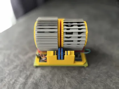
- Correct Orientation: Position the wheels so that their geared sides face inwards (towards the middle). This is essential for the gears to align properly with the servo motor gears.
2. Initial Flap Alignment (Homing)
The initial placement of the "00" number flaps determines the clock's calibration. This step is extremely important.
- Locate the Contact Point: Each wheel has a single, unique contact point designed to trigger its "home" limit switch.
- Position for Homing: Manually rotate each wheel until its contact point is perfectly aligned with and touching its respective home limit switch.
- Hang the "00" Flaps: While the wheels are held in this "home" position, hang the "00" flap for the hour wheel and the "00" flap for the minute wheel. This ensures that the physical "00" display corresponds exactly to the electronic home position.
3. Identifying and Attaching the Number Flaps
You will have two distinct sets of number flaps. It's important to identify them correctly before assembly.
- Hour Flap Set:
- Quantity: 24 pieces (for numbers 00-23).
- Identifier: The mounting hooks on these flaps are shorter than the minute flaps.
- Minute Flap Set:
- Quantity: 60 pieces (for numbers 00-59).
- Identifier: The mounting hooks on these flaps are taller than the hour flaps.
⚠️ CAUTION: Handle with Extreme Care
- The mounting hooks on the number flaps are small, delicate, and can break easily if too much force is applied.
- When attaching each flap to its wheel, you must be very careful. You will need to learn the right amount to gently bend or flex the flap to snap it into the wheel's holes.
- Do not force them. If a flap doesn't fit, check for any printing imperfections and try again gently. It is better to take your time than to break the parts.
Project Status: V1 Prototype (IMPORTANT - Please Read!)
This project is currently a "Prototype Version" and should be considered "In Development." This means:
- Not Fully Calibrated: The values in the provided source code, especially those related to the servo motors (SERVO_MOVE_OFFSET, SERVO_STOP_POSITION), are starting values only. You will need to experiment and fine-tune these parameters to get your servos to operate smoothly with your specific build.
- Mechanical Tolerances: 3D printers and filaments have varying tolerances. You may need to slightly scale the 3D models or sand/file the printed parts to ensure all mechanical components fit together and move freely without binding.
- Limit Switch Positioning: The physical placement of the limit switches is critical for accuracy. You will need to carefully adjust their positions to ensure they are triggered reliably at the correct point in the mechanism's rotation.
- DIY Is Required: This is not a "print-and-play" project. It is intended for makers who are willing and able to troubleshoot, tune code, and adjust mechanical parts. A foundational understanding of the components is expected.
In summary: I am sharing all files (3D models and source code) on an "as-is" basis to serve as a starting point and a guide for other makers.
I hope this project inspires you. If you build it, improve it, or have suggestions, please feel free to share your make and your feedback.
Happy Making!
License
You shall not share, sub-license, sell, rent, host, transfer, or distribute in any way the digital or 3D printed versions of this object, nor any other derivative work of this object in its digital or physical format (including - but not limited to - remixes of this object, and hosting on other digital platforms). The objects may not be used without permission in any way whatsoever in which you charge money, or collect fees.
Comment & Rating (17)