


Print Profile(1)

Bill of Materials


- Wemos D1 mini x 1: Or Arduino Nano, for Stepper motor signal
- 28BYJ-48 5V stepper motor x 1: driving the mechanism
- ULN2003 stepper driver module x 1: driving the stepper motor
- DC barrel jack x 1:
- 4x45mm brass rod x 2: recommend getting one long rod and cutting to size for shorter versions
- 4x15mm brass rod x 1:
- 4x70mm brass rod x 1:
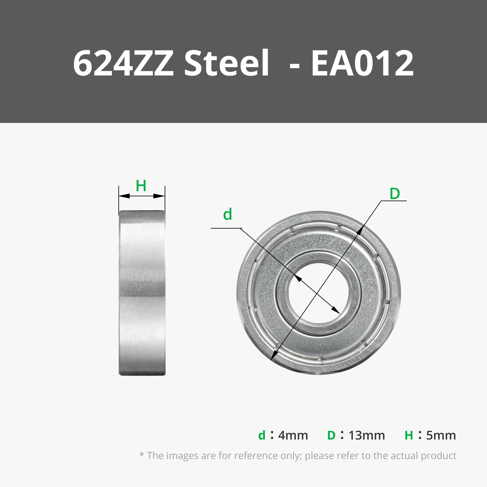
- 698ZZ bearing x 1:
- 20mm diameter steel ball x 1: big size to differentiate between minute and hour hand
- fine grain sand x 1: one hand full should be enough
- a few wires x 1:
Description

Inspired by the sand drawing tables and the beautiful project SAND watch by Studio AYASKAN, I decided to build my own sand-based clock with a little ancient theme.
The sand becomes the watchface as the two marbles draw the time as a line in the sand.
While Medusa, ehem, excuse me - Prusadusa(sorry Bambu - no Bambudusa yet) watches over them, ready to strike anyone trying to mess with time.
If you're not a fan of putting Prusas face on everything, you can substitute the “prusadusa” model for anything you like. The central pin is sticking out about 12mm and is 4mm in diameter, anything with a proper hole should fit. If you want to add time indicators to the watchface I'd recommend using roman or greek statues holding the numbers, to fit the theme.
UPDATE: I've added a few statues with numbers to make reading the clock a little easier, they are based on the fantastic Son of Niobe scan by GeoffreyMarchal (see file description for the link)
Printing Instructions
Printing most of the parts in 0.2mm and PLA should be good enough, for the LowerHousing and Watchface I would recommend to go with 0,15mm for the extra smoothness.
The Prusadusa should be printed using SLA, unfortunately it seems you can't combine SLA and FDM print files within one design, otherwise I'd have supplied the sliced file as well.
Assembly Instructions
Before I show you how to build this beast of a mechanical clock, I'd like to take the time to thank the original author of the beautiful Medusa model, I had the pleasure to redecorate with Jo Prusas face: Yasashii Kyojin Studio he has a multitude of wonderful sculpts available on his thingiverse account, so definitely check him out.
Boost Me (for free)
If you like this model, feel free to leave a boost. Thanks.
Find the Assembly Instructions below
What you'll need
To build this clock you'll need a few extra parts in addition to the 3D printed ones.

These tools might come in handy:
- Soldering Iron
- PC + Arduino IDE
- small Philips Screwdriver
- Superglue
- Pumpwrench/Pliers

Wiring Diagram

Assembly
Before your proceed: It's a good idea to prepare a spare arduino with the basic Arduino Stepper Example, so you can test your gears+stepper during assembly. Nothing is more frustrating than having to take the whole thing apart again after finding an issue in the mechanism the last minute. Test early, test often!
| 1. |  | Start by pushing all the bearings into the gears, depending on the accuracy of your printer you might need to use a pumpwrench or pliers to get the bearings to fit.
|
| 2. |  | Push the drive_gear_motor_side onto the shaft of the stepper motor.
|
| 3. |  | Fix the stepper motor to the motor-base with two M3 screws, be careful to align the hole below the stepper mount with the drive-gears pin.
|
| 4. |  | Push the 15mm brass rod into the drive_gear_intermediate, using pliers if necessary.
|
| 5. |  | Insert the drive_gear_intermediate into the slot next to the motor mount.
|
| 6. |  | Secure the drive_gear_intermediate in its place using the intermediate_gear_cap and two M3 screws.
|
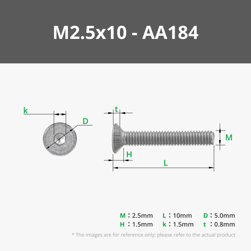
| 7. |  | Mount the stepper-driver board onto the small posts below the motor mount using your M2.5 screws.
|
| 8. | Now is a good time for a first test, connect your Arduino and the motor to the stepper driver and see if both gears move without issue. Depending on your printer you might have to give the gears and holes a little sanding to increase tolerances. If this initial test runs smoothly it's time to get your final Arduino ready. Upload the “firmware”(which you can find on github here: https://github.com/fluetke/sandclock_fw) | |
| 9. |   | Solder wires from your dc-barrel-jack onto the RAW(+) and GND(-) pins of your arduino, then connect your Arduinos VCC, GND and the motor pins you defined in the firmware with the stepper drivers corresponding pins. (see Wiring diagram) I used headers and jumper wires for my prototype, but you might want to solder the whole thing together, if you're not planning on taking it apart later. Route the wires between the stepper motor and the walls of the LowerHousing to make sure they don't interfere with the mechanics. |
| 10. |  | Arduino programmed? Motor connected? Good! Now it's time to assemble the gears. To keep things steady, you can add a little superglue to the left-most holes (when the stepper motor is on the right), before inserting the 45mm brass rods into them. You can mount the gear_plate to the top of the three pillars, to keep the rods aligned until the glue is dry. Whatever you do, don't put glue in the center hole, this is where the main axle will need to rotate later. |
| 11. |  | Grab your 70mm brass rod and the drive_gear_1rpm_seconds_axle. Push the gear onto the rod, so that its teeth sit about 4-5mm from the end of the rod. You might need to superglue the gear onto the rod, if your printer is very precise and there is no friction fit between gear and rod. The rod will later rotate once every minute and help move the seconds hand of the clock. |
| 12. |  | Insert the 70mm rod into the central hole, carefully aligning the gear with the intermediate_gear.
|
| 13. |   | Next, take the 1st_reduction_gear(it has a small angle next to the bearing) and push it on the leftmost brass axle(the one furthest away from the motor) right down to the bottom. Be careful to match the gearing with the drive_gear_1rpm_seconds_axle. |
| 14. |
  | Push the 2nd_reduction_gear_standoff onto the remaining axle without gear. Then push the 2nd_reduction_gear onto the same rod, again carefully aligning the gear to the 1st_reduction_gear's output gearing. |
| 15. |   | Depending on your tolerances you might need to add the 3rd_reduction_gear_standoff onto the leftmost axle, then push the 3rd_reduction_gear onto the same axle. With this setup you might want to run another test of your mechanical setup, by running the stepper motor again, make sure everthing runs smoothly. |
| 16. |  |
If everything runs ok, add the 4th_reduction_gear onto the central axle, this will later drive our minute hand. |
| 17. |  | Next add the 5th_reduction_gear_standoff to the leftmost column and then insert the final gear for the leftmost axle, the 5th_reduction_gear.
|
| 18. |   | Take the 6th_reduction_gear_hourDrive and push it onto the 8mm pillar of the 4th_reduction_gear.
|
| 19. |  | Complete the assembly of the clockwork by installing the gear_plate to keep the different axles aligned.
|
| 20. |   | Time to prepare the hour and minute hands of your clock. Take the printed parts hour_hand, minute_hand and the neodymium magnets and glue the magnets into their respective recesses on the hands. |
| 21. |   | After the glue has dried, install both hands onto your clockwork. First push the hour_hand onto the pillar of the 6th_reduction_gear and the minute_hand onto the pillar of the 4th_reduction_gear. |
| 22. |    | With the clock hands assembled you now have one last chance to test your assembly before putting the cover plate on. It makes sense to run the clock for a full cycle of 12 hours now, to check if there are any issues left unnoticed. Set the hands to the 12h position to give them a nice starting point(I recommend using on of the 6 screw mounts for the watchface as a guide.
Then connect the power and let the clockwork run for the next 12 hours (or use a test-firmware with a slightly higher motor rpm if you're impatient :-) |
| 23. |   | Now that your clockwork has passed it's final test(hopefully) you can mount the watchface on the top to close of the mechanics department. Insert your last 624Z bearing into the bottom of the watchface. Secure the watchface on the top using the 6 remaining M3 screws. |
| 24 |  | Fill the plate of the watchface with fine-grained sand(quick headsup: the one used in the picture did turn out not to be fine enough) until you've reached the line on the central cone(about 2-3mm). Set your 10mm steel ball onto the minute_hands magnet and the bigger 20mm steel ball on the outer edge of the watchface on to of the hour_hands magnet. They should snap into position once you're close enough. |
| 25 |  | Finally top of the “Prusadusa and the sands of time” clock by glueing the Prusadusa model onto the central pin sticking out of the cone in the middle. This is now your seconds hand.
|
Boost Me (for free)
If you've made it this far, feel free to leave a boost and a comment to show of your build.
Comment & Rating (0)