
H2C/D Modular Nozzle Management System (4-12 AMS)
Print Profile(15)


Bill of Materials









Description
Update December 26th 2025:
Major Upgrade Part has been released as a separate Print Profile. The modular NMS has just become significantly more capable!
After releasing the "Four in Two" adapter, which can replace the NMS in certain situations,
I received some very positive feedback regarding its low resistance.
It was repeatedly emphasized that the resistance is significantly lower than that of the NMS.
While this is very gratifying, I couldn't accept that this system, into which I invested countless hours of work and which is much neater and more visually appealing, doesn't perform as well as the new device.
I therefore spent many more hours working on this upgrade.
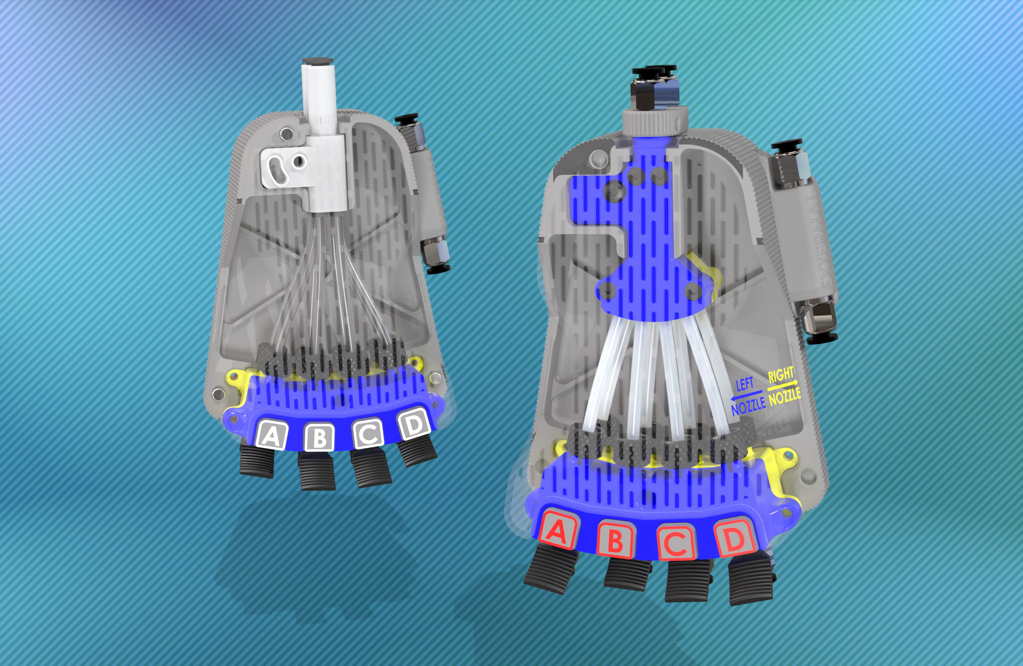
The technology of the internal splitter is very similar to that of the "Four in Two."
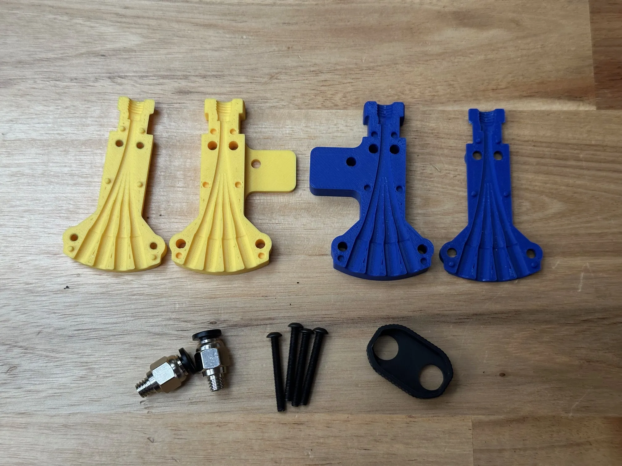
The intersection of the filament paths could thus be shifted significantly higher, resulting in straighter filament paths.
The slight S-curve that existed previously is now just a one-sided bend with a larger radius.
Furthermore, the tubes are all on the same plane, so the curvature in a second axis of the coordinate system, which was necessary due to the 4-in-1 adapters, is also eliminated. I promise that the overall resistance, especially for the two outer paths, is SIGNIFICANTLY lower than when using two Bambu 4-in-1 adapters.
Significantly smaller is a big statement, but how much smaller is it actually?
To illustrate the difference, which is otherwise only perceptible by touch, I filmed this video using two different spring scales.
If you're only interested in the data: The old version had a resistance of about 1.5 Newtons, while the new one only has about 0.6 Newtons. The resistance has therefore more than halved – I'm very, very happy with the result of the upgrade.
I will expand the documentation accordingly soon. For now, here is the most important information for switching to the new system:
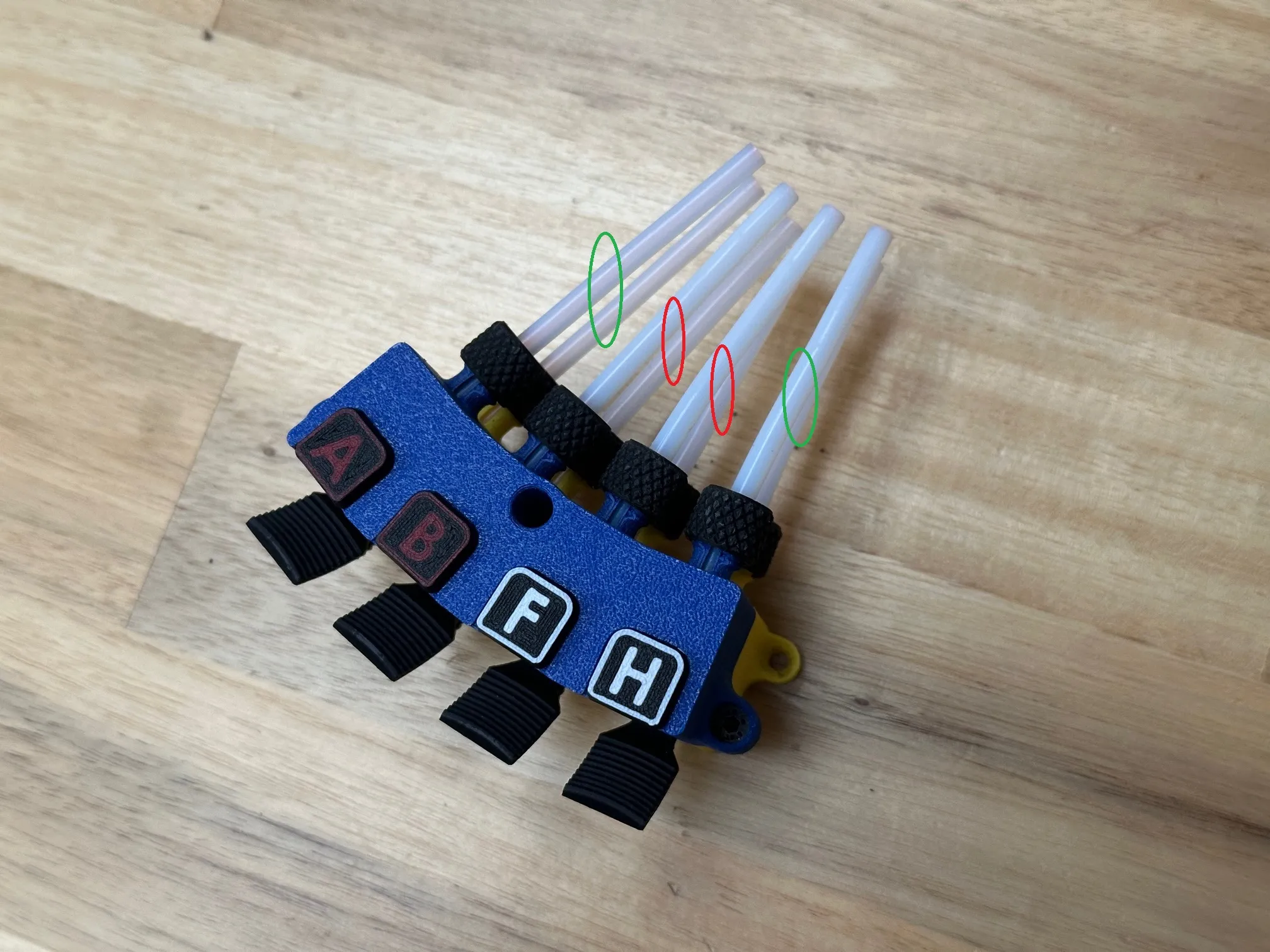
The outer four tubes between the new part an the sliding mechanism (green), need to be 63,5mm long, the inner ones 62,5mm
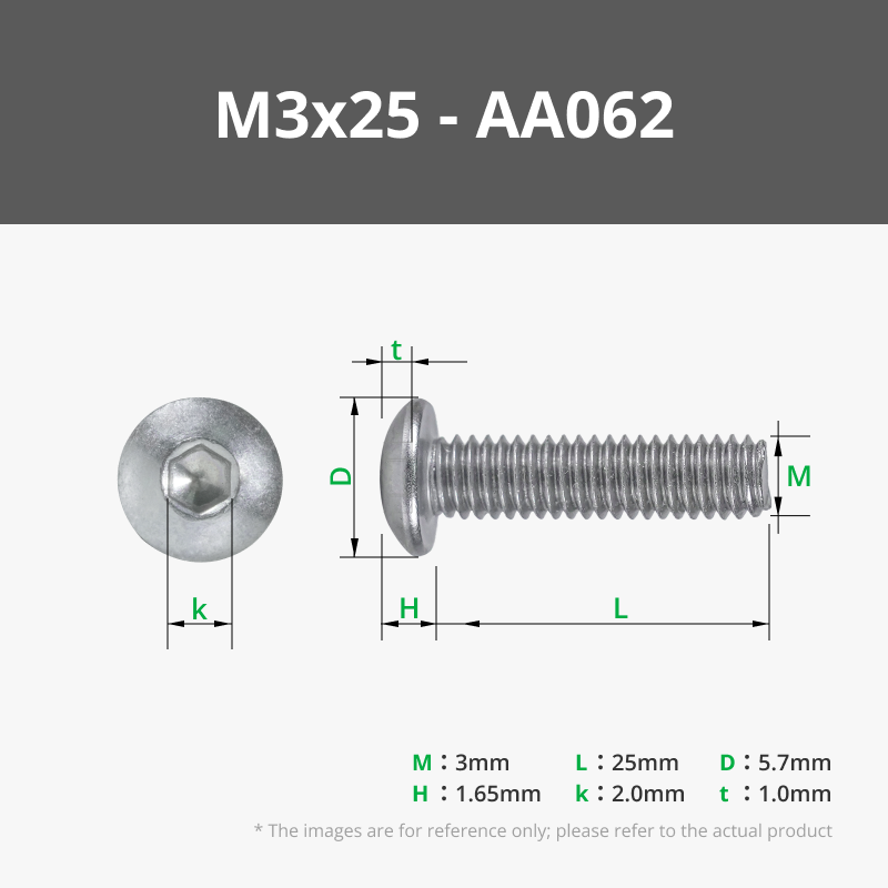
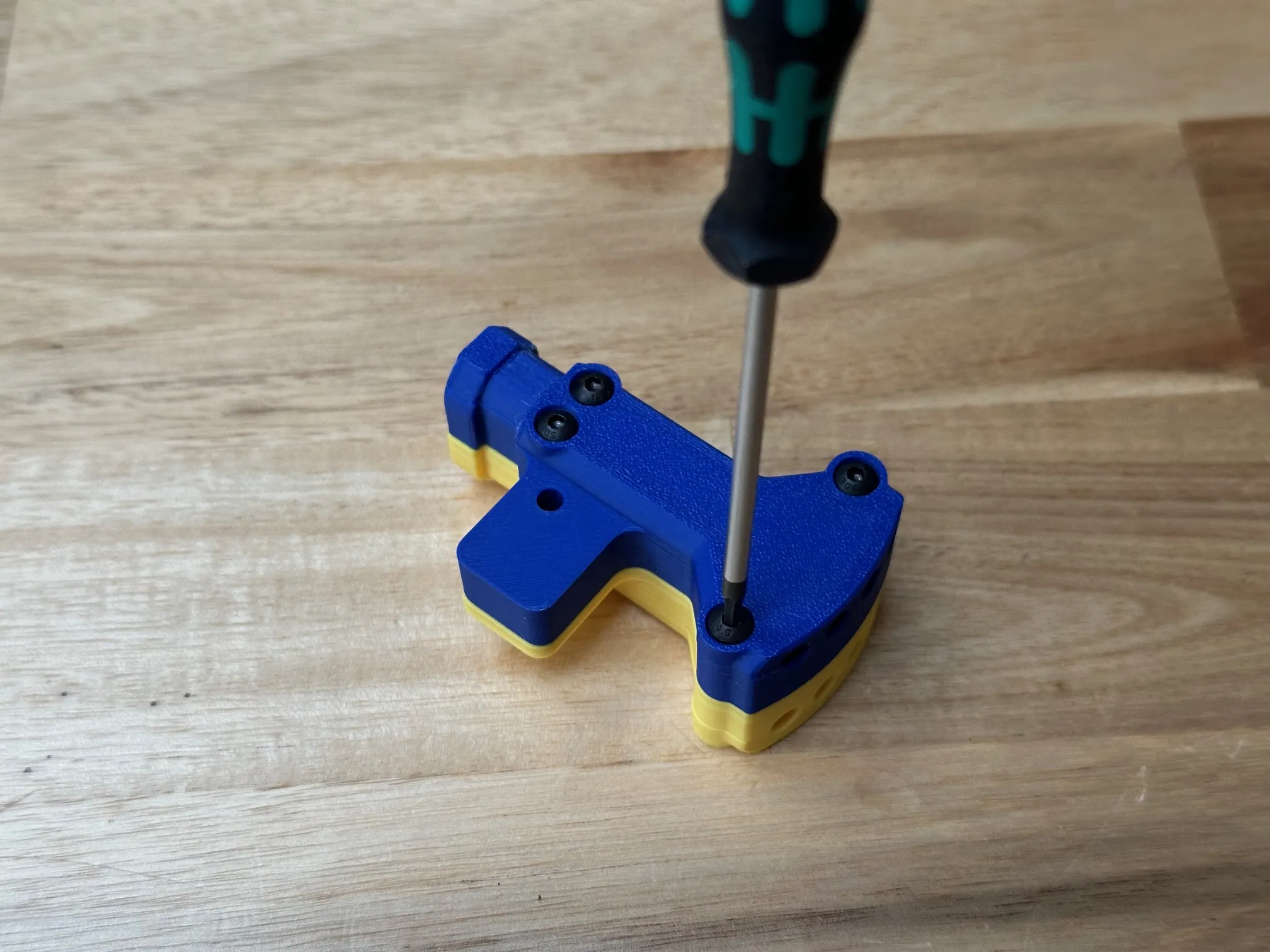
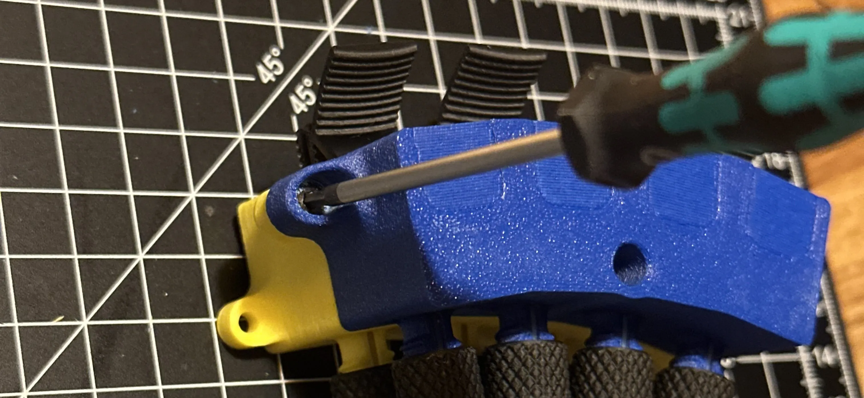
The four sections are sandwiched together with four BT3x25mm OR M3x25mm screws.
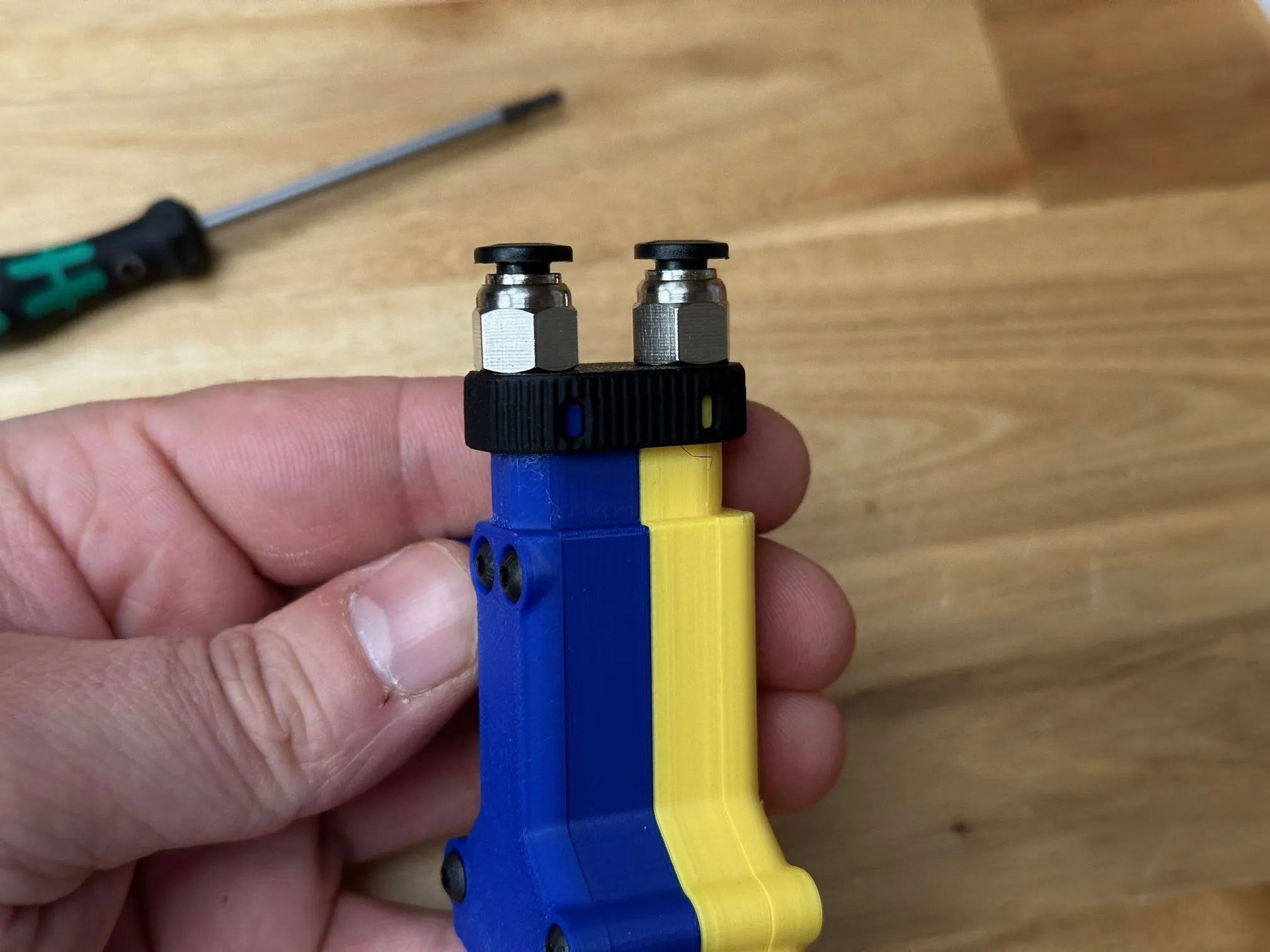
I recommend using PC4 M6 PTFE Tube Fittings from bambu lab store, they meet all the necessary requirements (article FC001)
Aside from the modified hose length and the assembly of the upgrade part, the installation of the entire system works exactly as described below. The new part fits plug-and-play into the existing setup; no other parts need to be reprinted.
Update early December 2025:
I know some of you have come across this model but can't use it optimally, especially since the mounting position on the printer is heavily customized to my own setup.
I've designed the “Four in Two” for all of you, which includes the core functionality of the NMS! https://makerworld.com/en/models/2055763
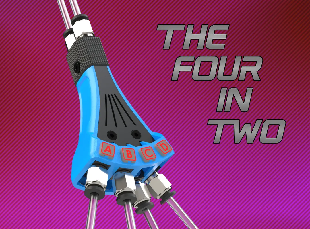
Thanks to its compact design, this alternative can easily be integrated into a wide variety of setups.
Update august 30th 2025:
A conversion kit has been added to replace the printed compression fittings on the couplings (inputs) with PC4 M6 fittings.
You can print this if you prefer hardware connectors instead of my printed compression fittings!
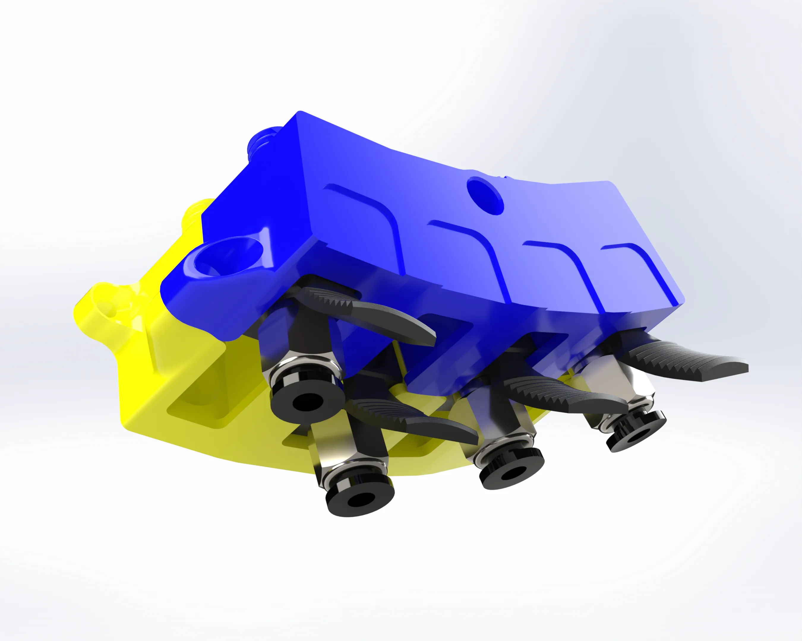
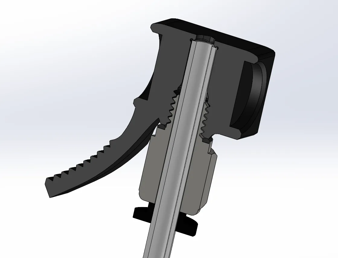
It is very important, to use the kind of fittings that allow you to push the PTFE tube THROUGH!!
check the linked option in the bill of materials. Bambu sells this exact type of M6 Fitting.
You can find the new parts as a separate print profile . In addition to the new couplings, a new manifold also needs to be printed, the cutout slots in the bottom of the parts have been made wider to make room for the fittings. You could alternatively remove some material from your existing manifold.
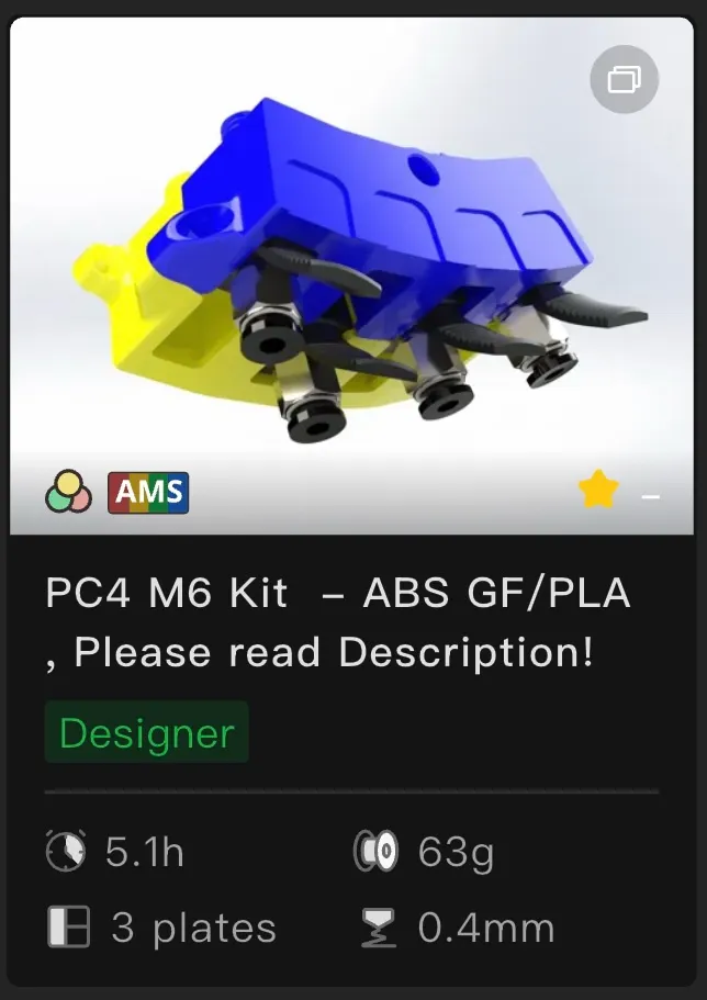
If you already completed the model, you can update it with the new parts if you like. If you have'nt started printing it yet and want to have this version right away, you need to substitute the corresponding plates in the main profiles (those that say “ALL PARTS”.
Now back to the model and how it works!
---------------------------
Hi there,
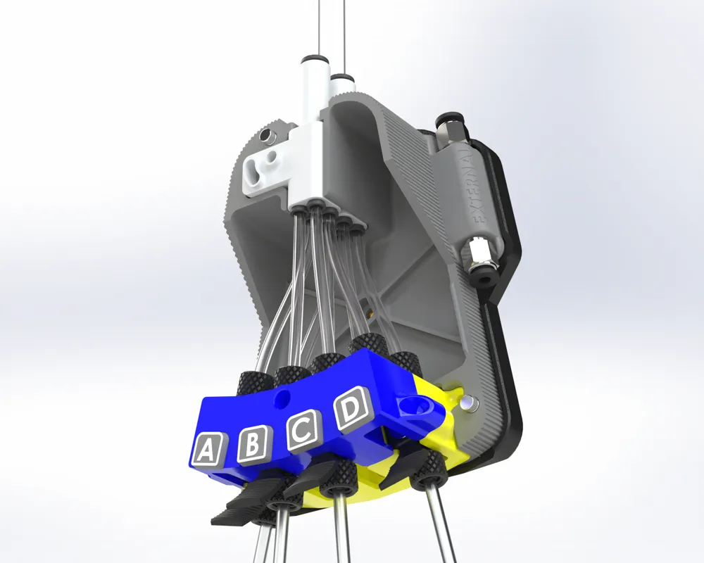
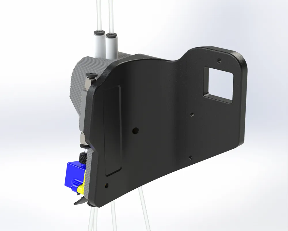
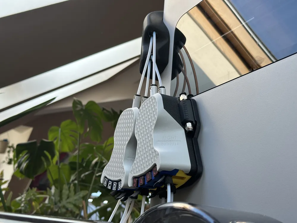
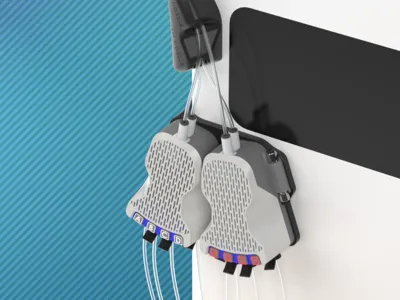
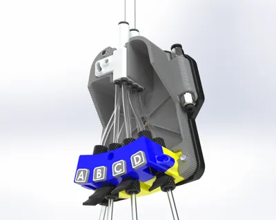
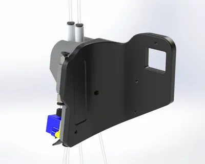
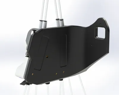
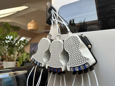
Say hello to the new version of my nozzle management system!
Boost Me (for free)
My projects tend to be very time consuming. This one has been the greatest effort i‘ve ever taken for a model. I did this for the community. Free access for everybody.
Please consider hitting the boost and like buttons to support me for future projects! Kind regards, M.I.M


Running the H2D with a multiple AMS System can be a bit complex and time consuming. If you want to make good use of the dual nozzle toolhead, you regularly have to fiddle around with the 4in1 adapters to use the machine to its full potential (Or change spools very often).
For a two material print, you want to use the toolhead to perform material changes, not the AMS. If you do a lot of experimental printing like me, you will end up having to change your left/right nozzle configuration for every other print.
Despite its good and reliable function, especially disconnecting PTFE tubes from the compact 4in1 adapter to change your AMS configuration is not an enjoyable task if you ask me. Especially if your printer is set up in a tight space.
Imagine you have to move the whole machine to perform a simple change 🤯
Not anymore. Switching is now super easy and can be done with two fingers. In less than a second.
After the changes, you will need to run the automatic AMS detection so the machine also knows how everything is connected!
It takes about 20-30 seconds per AMS unit. So if you have a huge setup, it can take a few minutes to complete. For minor changes, like only changing nozzle for one AMS unit, the manual mode is much more convenient!
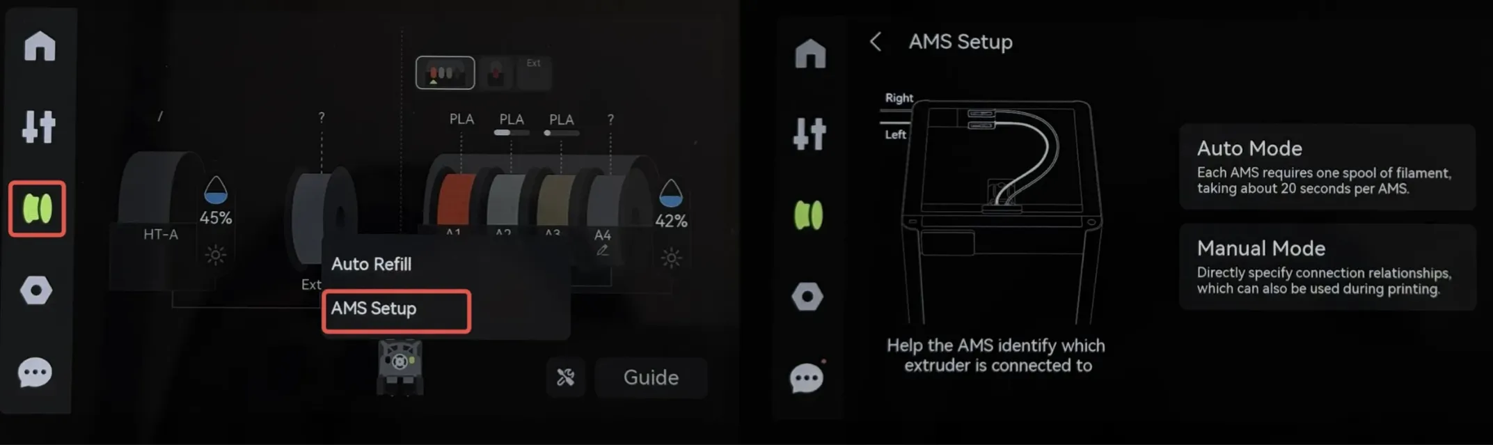
This function lets each AMS feed filament from one of the spools and the printer detects which buffer and nozzle it ends up reaching.
As said, it can also be set manually, which saves you a few minutes of time if you only made a small change.
The reactions to my first version have been overwhelming - thanks to each and everyone of you!
(https://makerworld.com/models/1387281)
There has been several requests and suggestions for changes, including my own - I tried to take all wishes into account as best as possible.
-solution for smaller setups
-solution for bigger setups
-external material pass through
-customizable lettering
-easier printing cover
-printable on a wider variety of printers
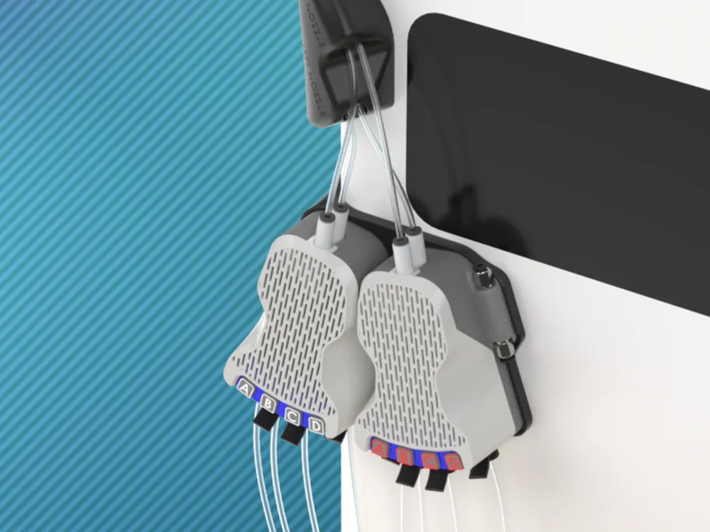

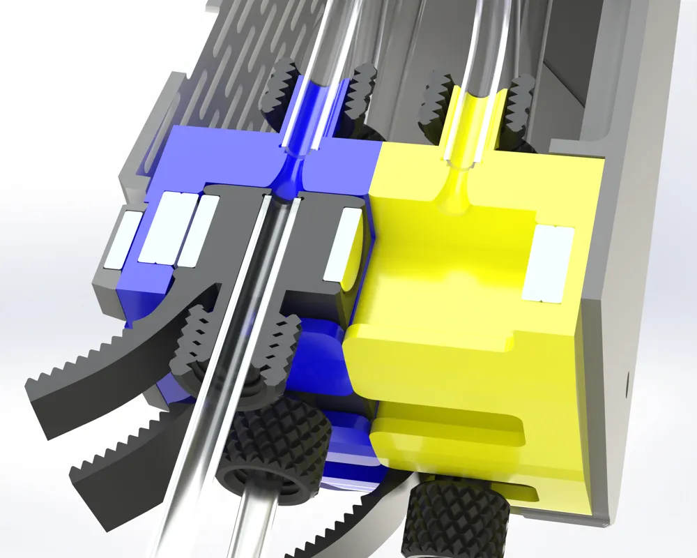
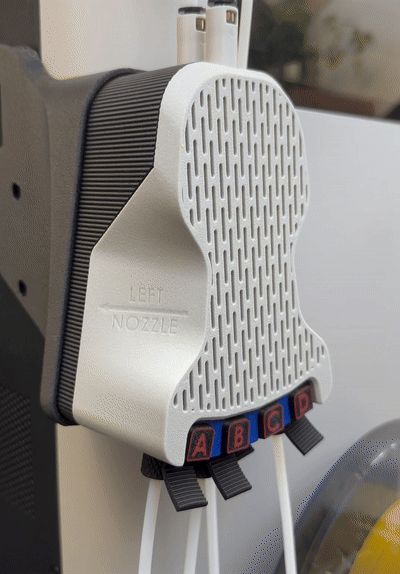
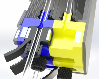
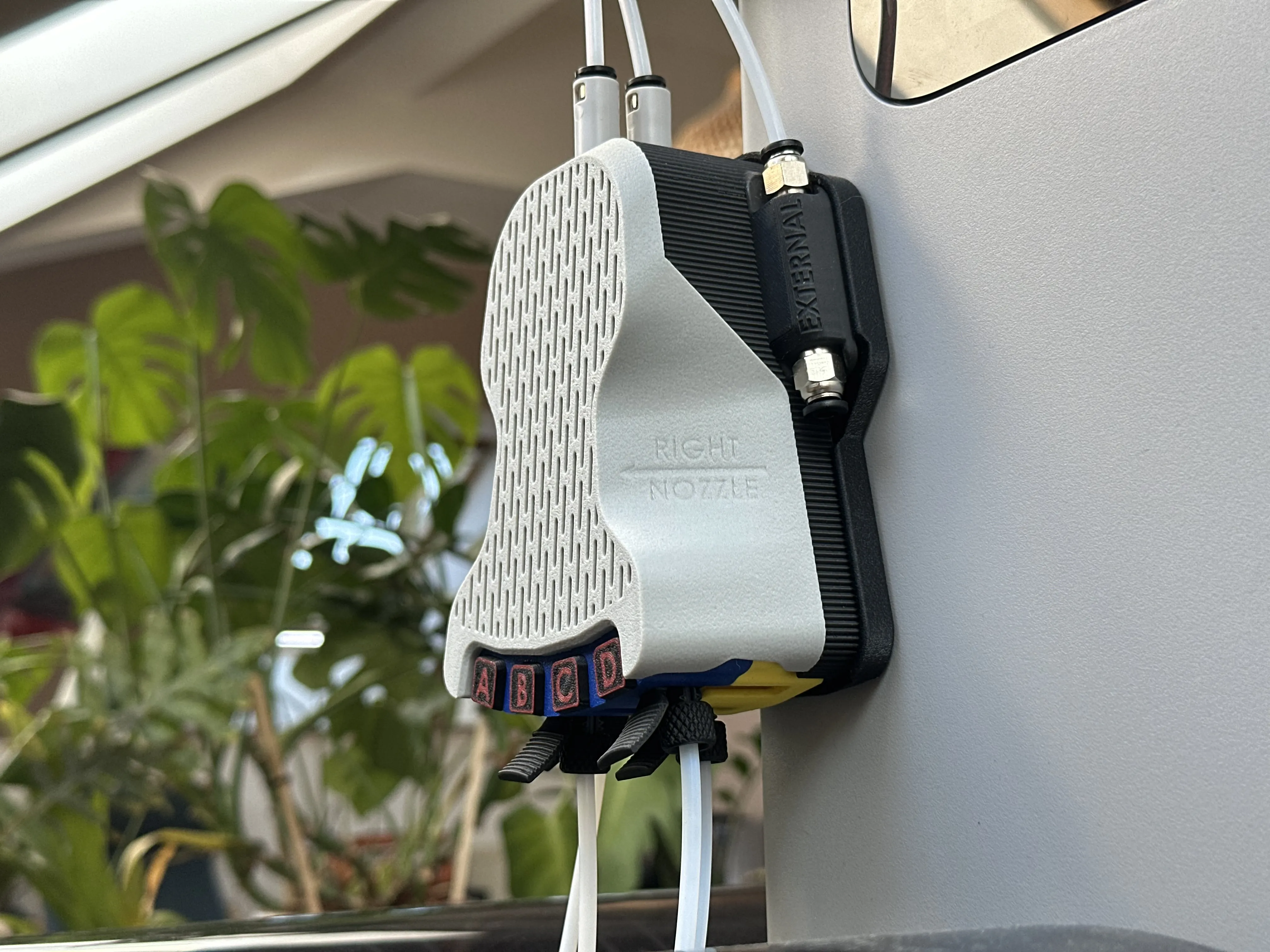
Besides that, i completely redesigned the switching mechanism. Instead of having to remove the couplings for nozzle switching, they just slide back and forth in their individual slots, to align with the desired filament path (left or right nozzle).
This, and the new tilted arrangement of the slots helps making the unit more compact, while still being able to switch all connected AMS units to one nozzle if needed.
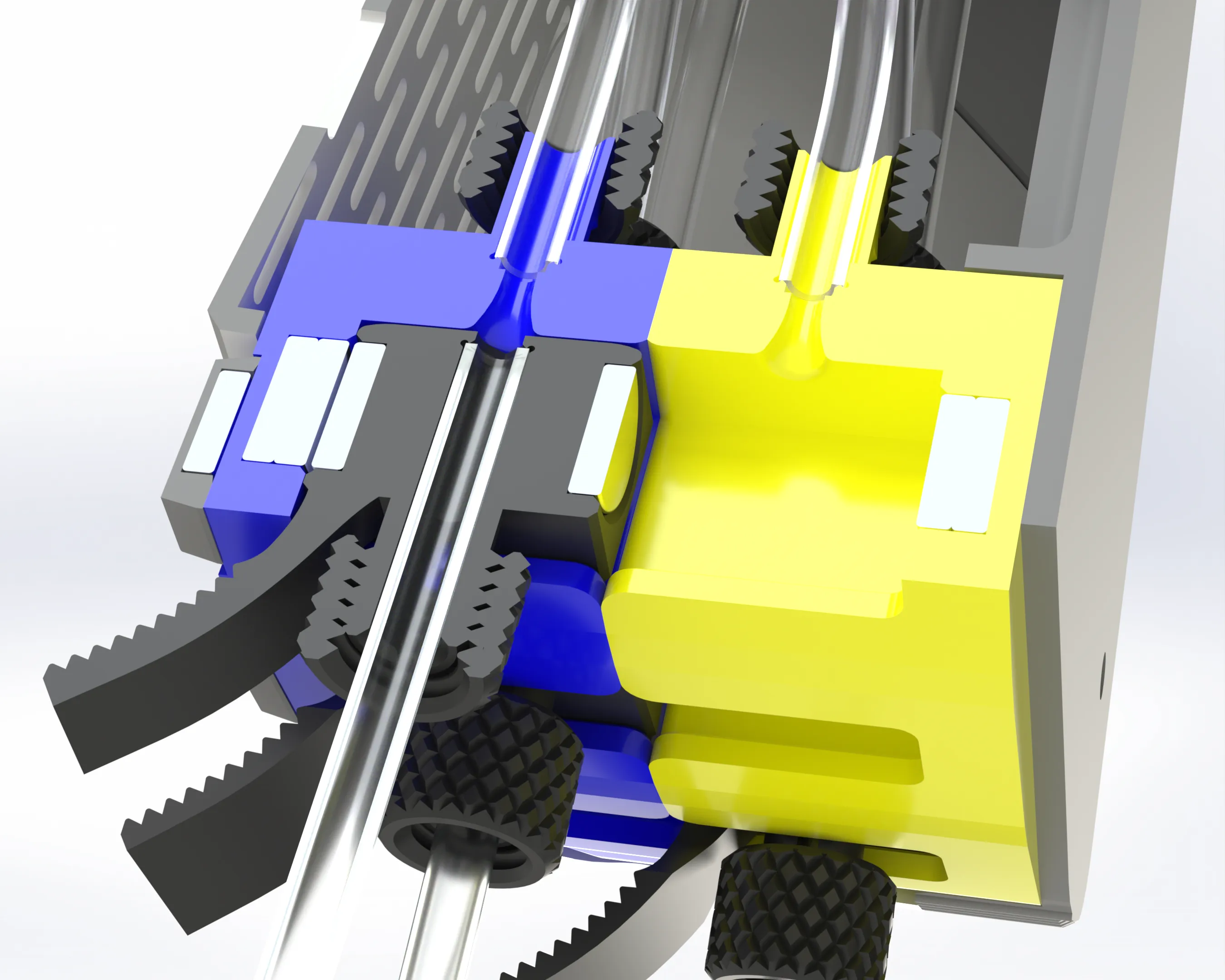
This switching method reduces the PTFE tube crossings below the NMS unit after extensive setup changes down to zero.
The couplings, as well as the slots, are equipped with magnets so they lock in in one of the two positions.
As soon as the filament passes the interface, the respective coupling is locked and impossible to move.
So please don't worry about "accidental nozzle changes." :D
Also, there are not really any forces caused by the traveling filament, that are pushing the couplings sidewards.
I initially planned to do dedicated versions for 4, 8 and 12 AMS.
After a few attempts, i ditched this plan, mainly for the following reason:
Both the 8 and 12 AMS version need two 4in1s per filament path, both of which would have had to be integrated into the housing, which would have resulted in a huge triangular box that did not look good to my eye.
I decided to split it up.
In my extensive tests, the two adapters in line per path did not cause any problems for AMS performed feeding or retraction, which was my main concern about a setup like this.
If you connect 4AMS/8HT, you would need to use two in line anyway, so this setup is basically also approved by bambu:
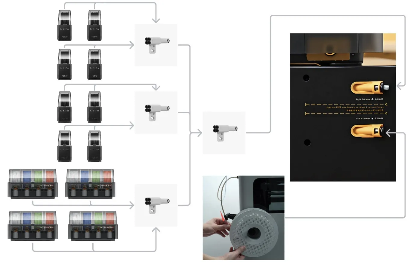
This schematic is from the official AMS connection guide for the H2D.
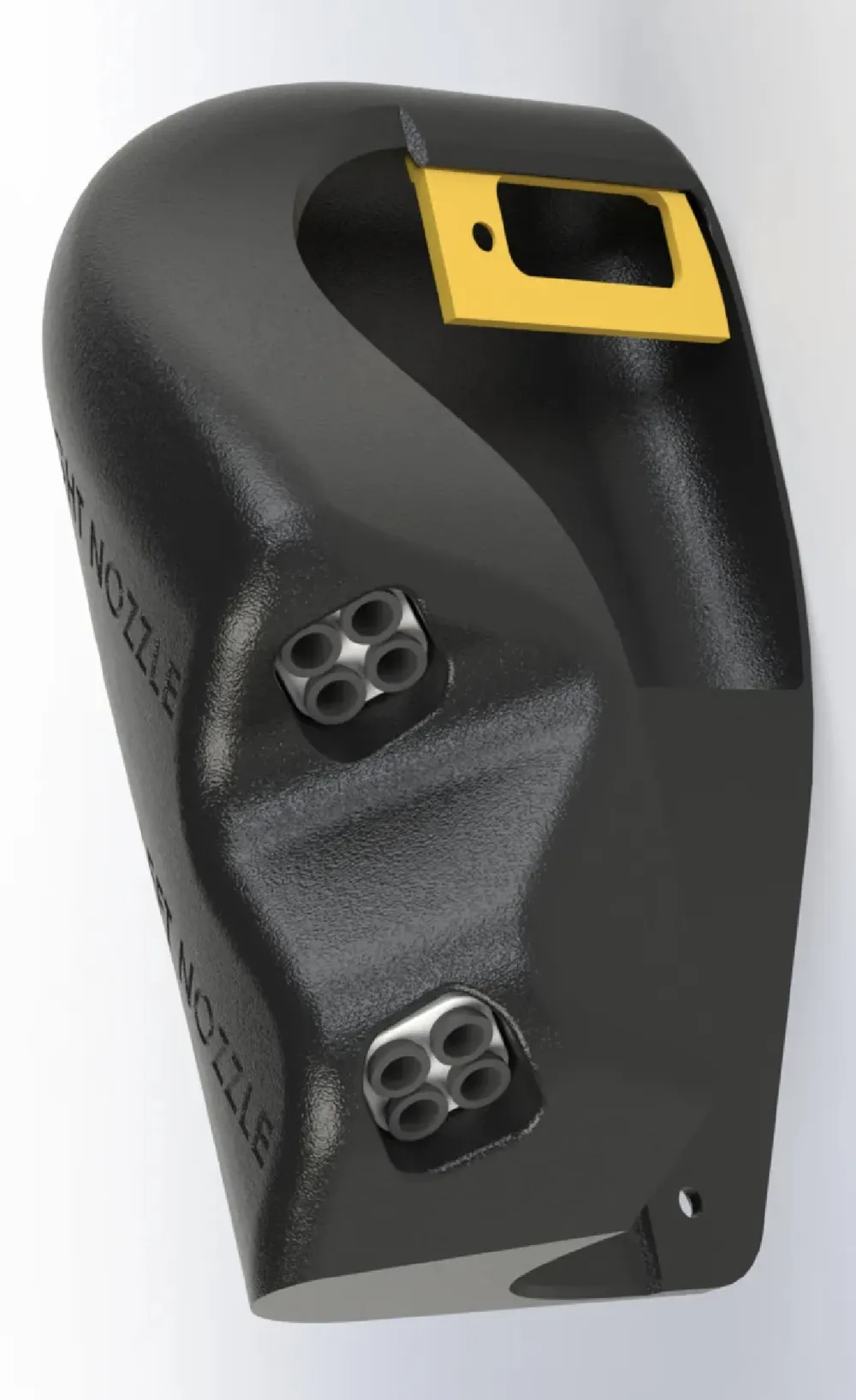
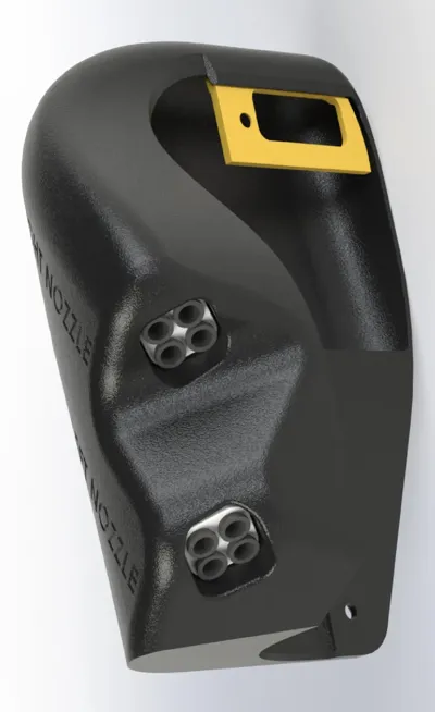
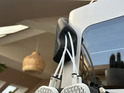
Each module carries two 4in1 adapters (one for each side/nozzle). The second stage splitters (only needed for the 8 or 12 AMS setup) are installed in this (!optional!) input terminal cover:

This way, the individual paths are kept more straight and tubes can be longer without having to increase the size of the actual switching modules.
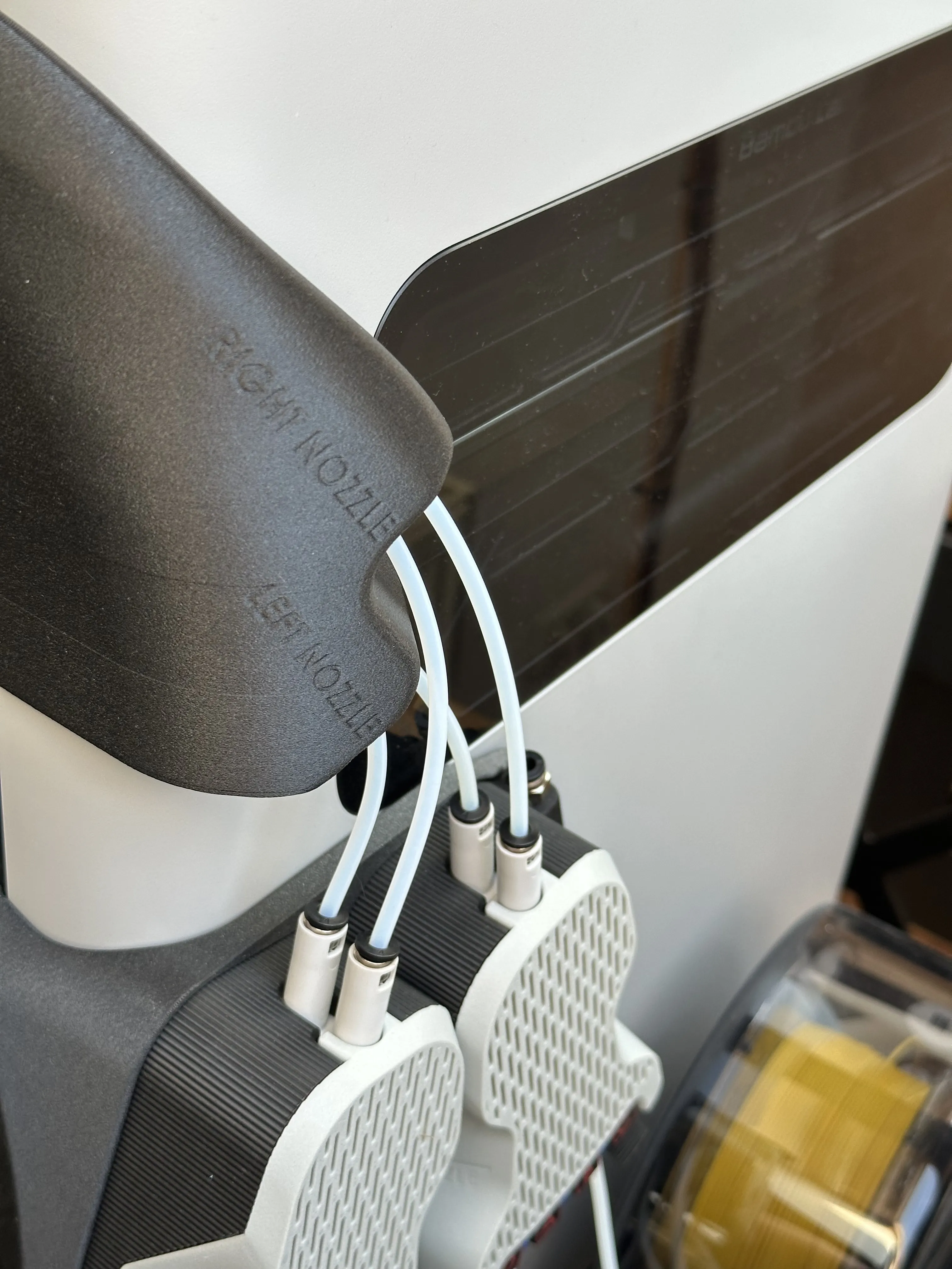
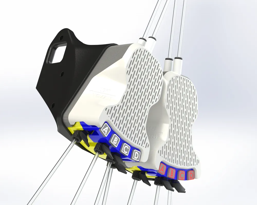
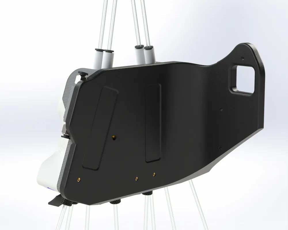
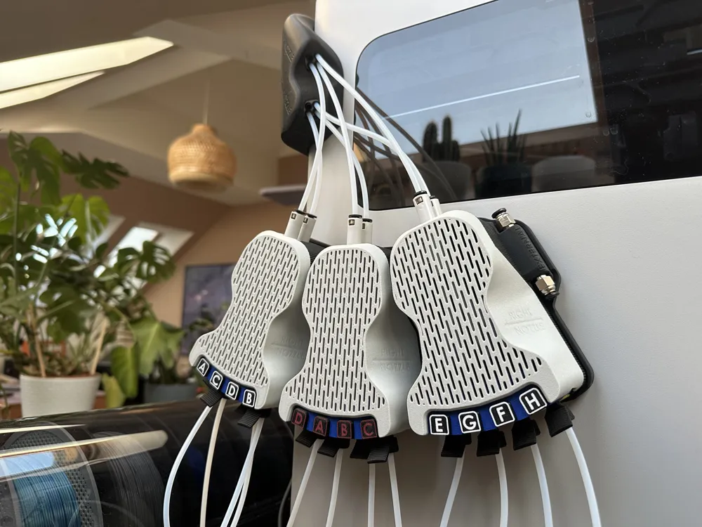
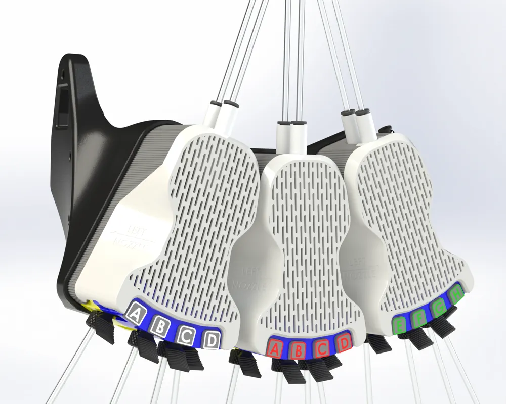
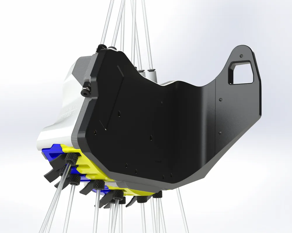
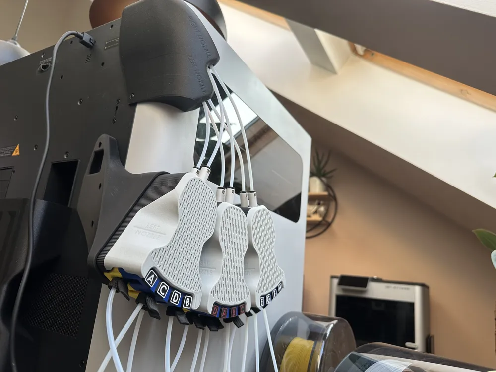
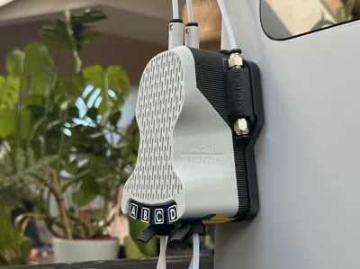
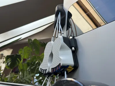
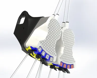
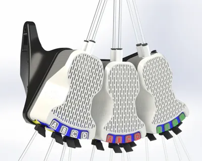
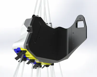
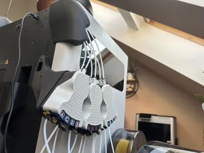
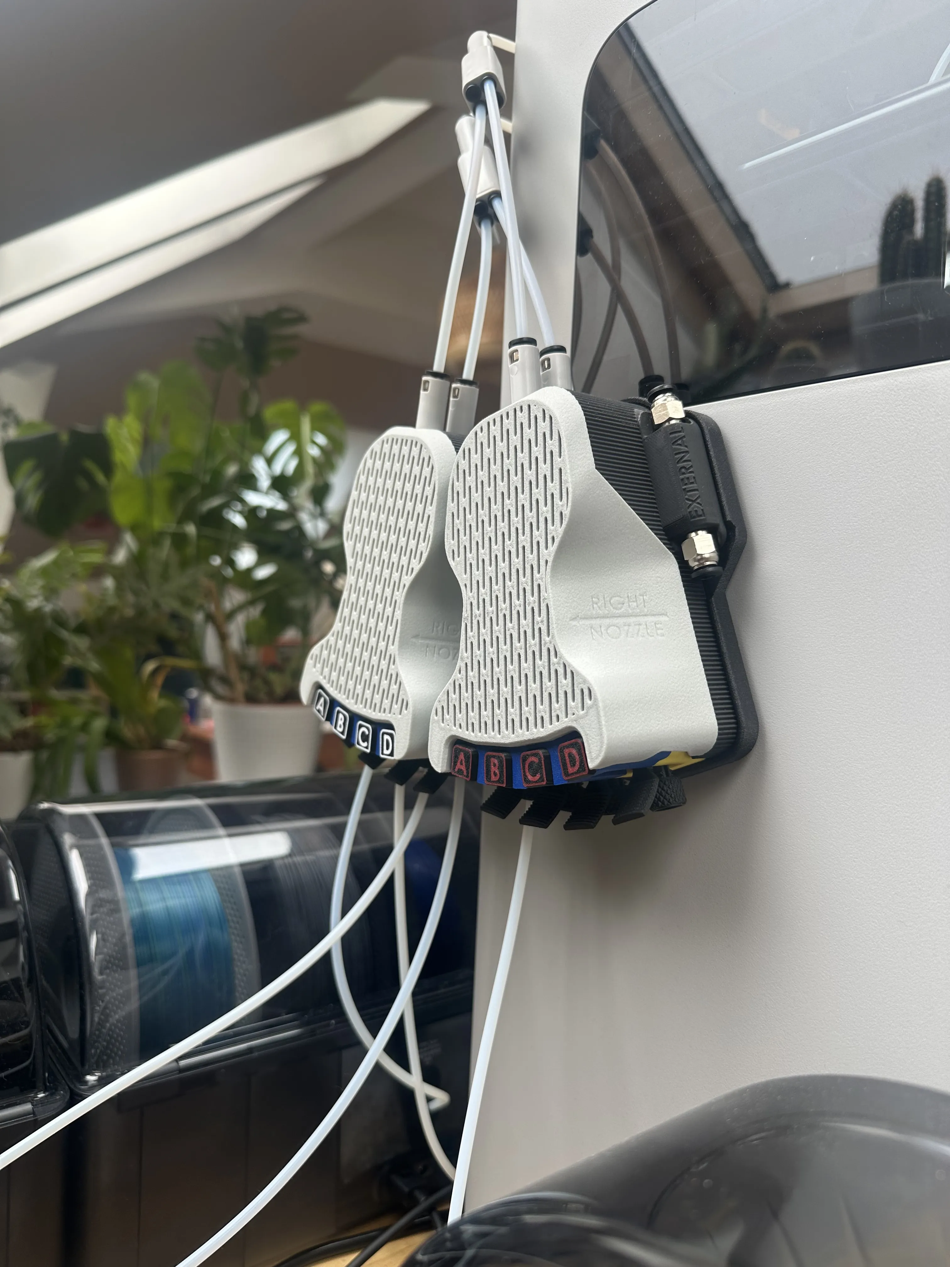
This modular system can grow with your setup! If you start with only two or three AMS and add further units, you can now just print an additional module and one of the holders for multiple modules. No need to replace the whole system!!
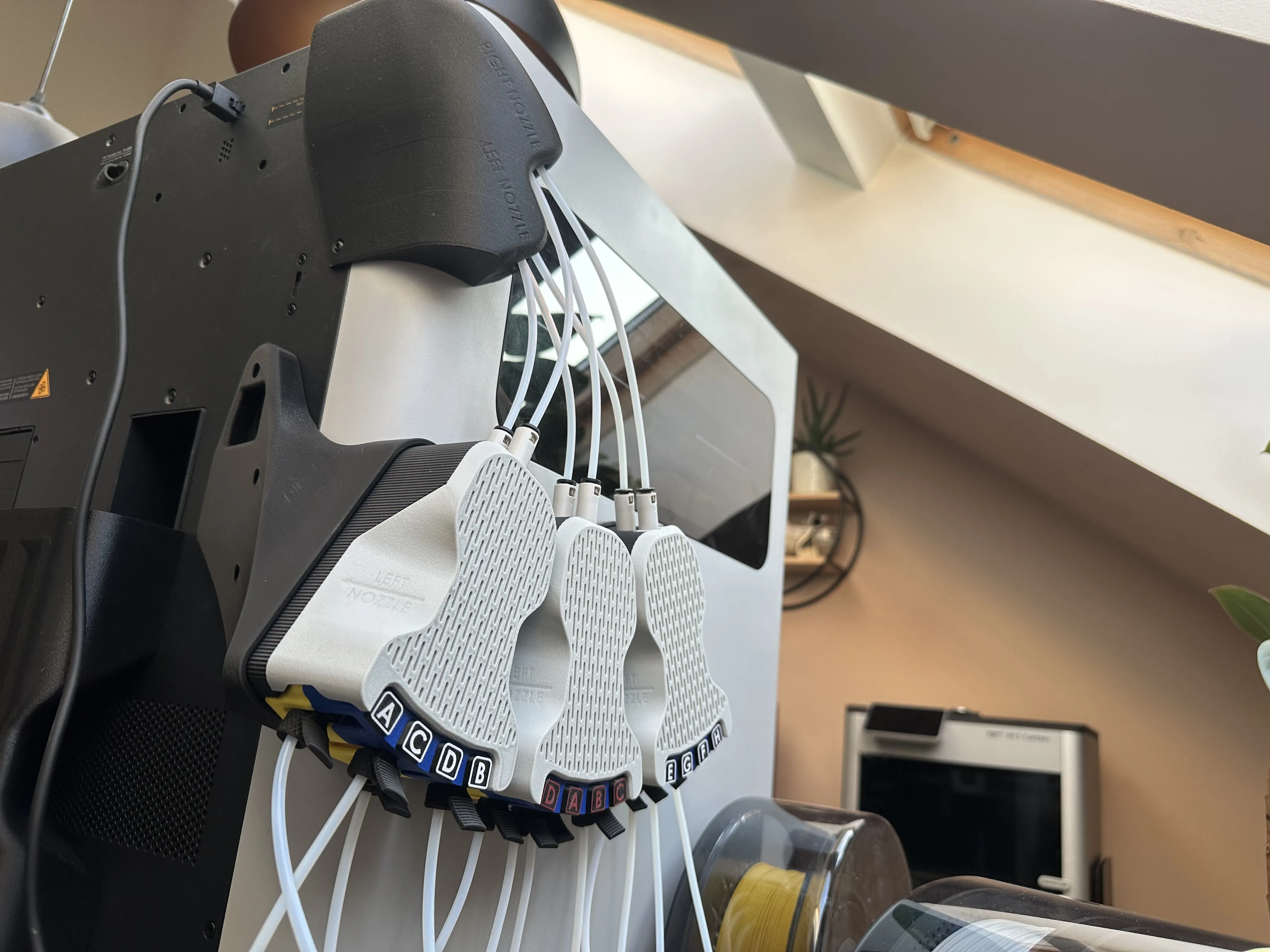
The different holders that i provide are designed to hold 1-3 switching modules.
There is two different types of modules by the time of writing this.
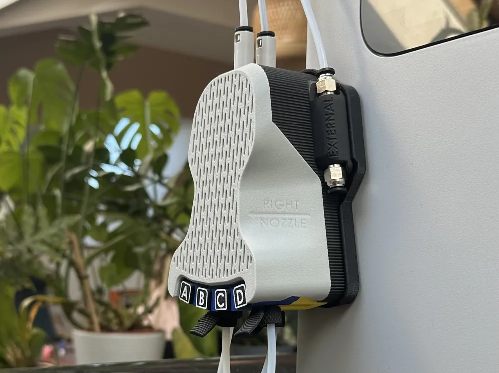
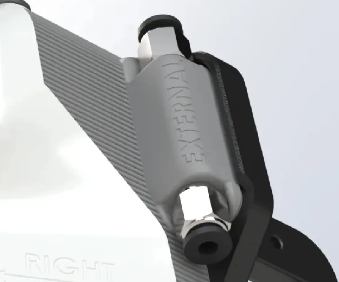
Module A = with external pass through
Module B = without external pass through
Module A has to be in the position on the right side of the holder to align with this section of the holder,
The other modules have to be B units. (for the 8 or 12 AMS options)
##########################
######### HARDWARE ########
##########################
__________________________________________
***** MODULES (this is the parts list for ONE module (A or B) without holder) *****
2 Pcs - Bambu 4in1 Adapters
350mm PTFE Tube with 2,5mm inner diameter
24 Pcs - 10x2mm round magnets
6 Pcs - 5x3 round magnets
4 Pcs - 8x2 round magnets
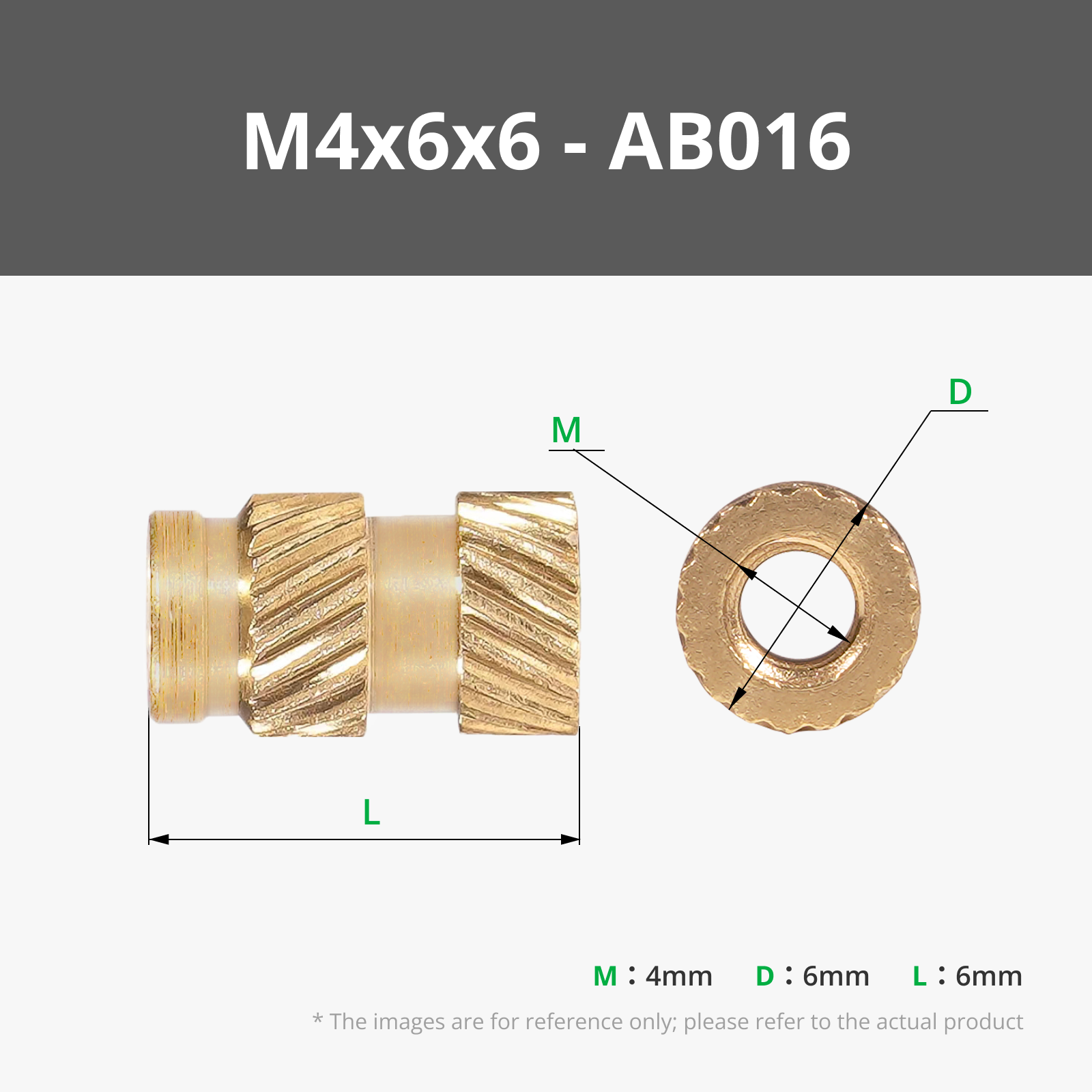
4 Pcs - M3 heat set inserts (max. 5mm high)
3 Pcs - M3x8mm countersunk screws
1 Pcs - M3x25mm buttonhead screw
Optionally (Updated on 30th of august 2025):
4-12 Pcs PC4 M6 PTFE Tube FIttings,
if you want to print the version with hardware fittings!
The B.O.M of maker supply articles mentions two packs of five, which is enough to assemble one module A or B. If you print multiple moduls, please adjust the count of fittings for your own needs!
It is very important, to use the kind of fittings that allow you to push the PTFE tube THROUGH!!
check the linked option in the bill of materials. Bambu sells this exact type of M6 Fitting.
Module A also needs:
2 Pcs - M6 PTFE Tube fittings
(Again, the ones that allow to push the tubes through)
___________________________________________
***** HOLDERS *****
2 Pcs - M3x10mm buttonhead screws
One existing screw of the printer
Some sort of soft material to put on the recessed areas of the holders to keep the holders from banging against the machine!!
The recess is 0.8mm deep, so the insulation material should be slightly thicker than that!
Preferably felt tape or 3M adhesive for the 3 Module version. The
I'll list an option from bambu maker accessory in the B.O.M. that you could use multiple layers of.
Per Module:
2 Pcs - M3 heat set insert (max 6mm high)
1 Pcs - M4 heat set insert (max 6mm high)
2 Pcs - M3x8mm countersunk screw
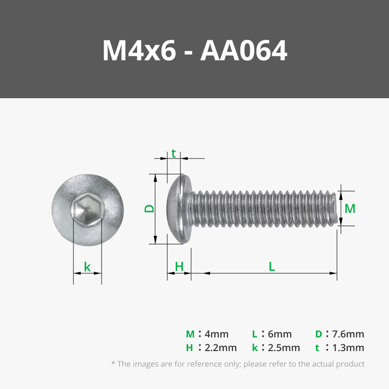
1 Pcs - M4x6mm button head screw
____________________________________________
***** INPUT TERMINAL *****
2 Pcs - M3 heat set insert (max 6mm high)
more PTFE Tube, you should have a few meters in total
2 Pcs - M3x12mm button head screws
1 Pcs - M3x8mm cluntersunk screw
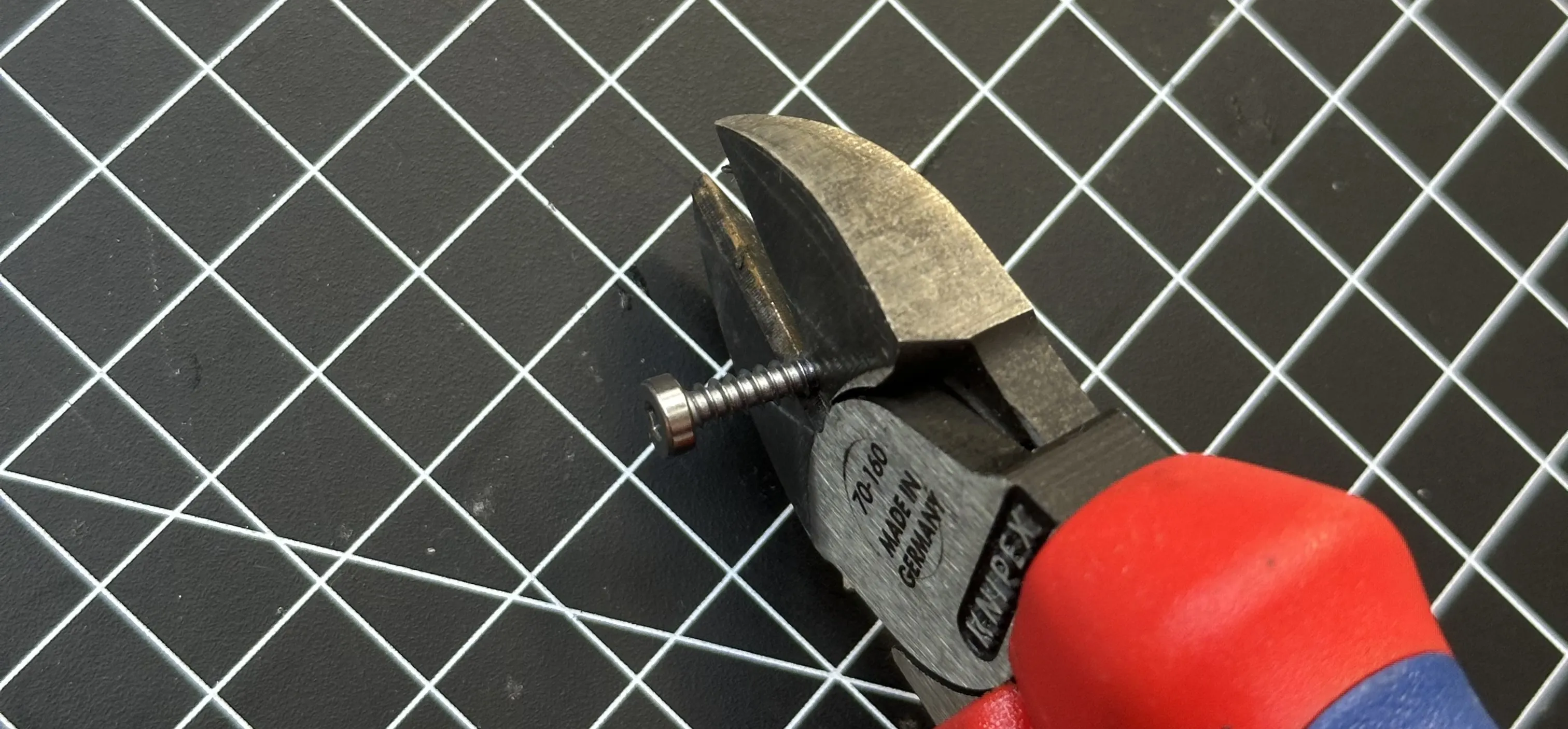
1 Pcs - 3mm self cutting crew, roughly 8mm thread length. i used one of the screws that attached the AMS inside the printer for shipping, and cut it to length. Use some good side cutter pliers, these kind of screws are much more forgiving than Metric screws, as far as cutting goes…
########################
######### PRINTING ########
########################
I recommend using the Textured PEI Plate for all objects. Make sure the plate is cleaned well.
(Dish Soap, Fresh Sponge, HOT Water, Ellbow grease :D)
The profiles for the modules use two different support interface materials: Support for PLA, Support for ABS/ASA
If you print from Bambu Handy, please do not attempt to substitute the interface materials with the Material that is used for the model. You will end up with impossible to remove supports!!!
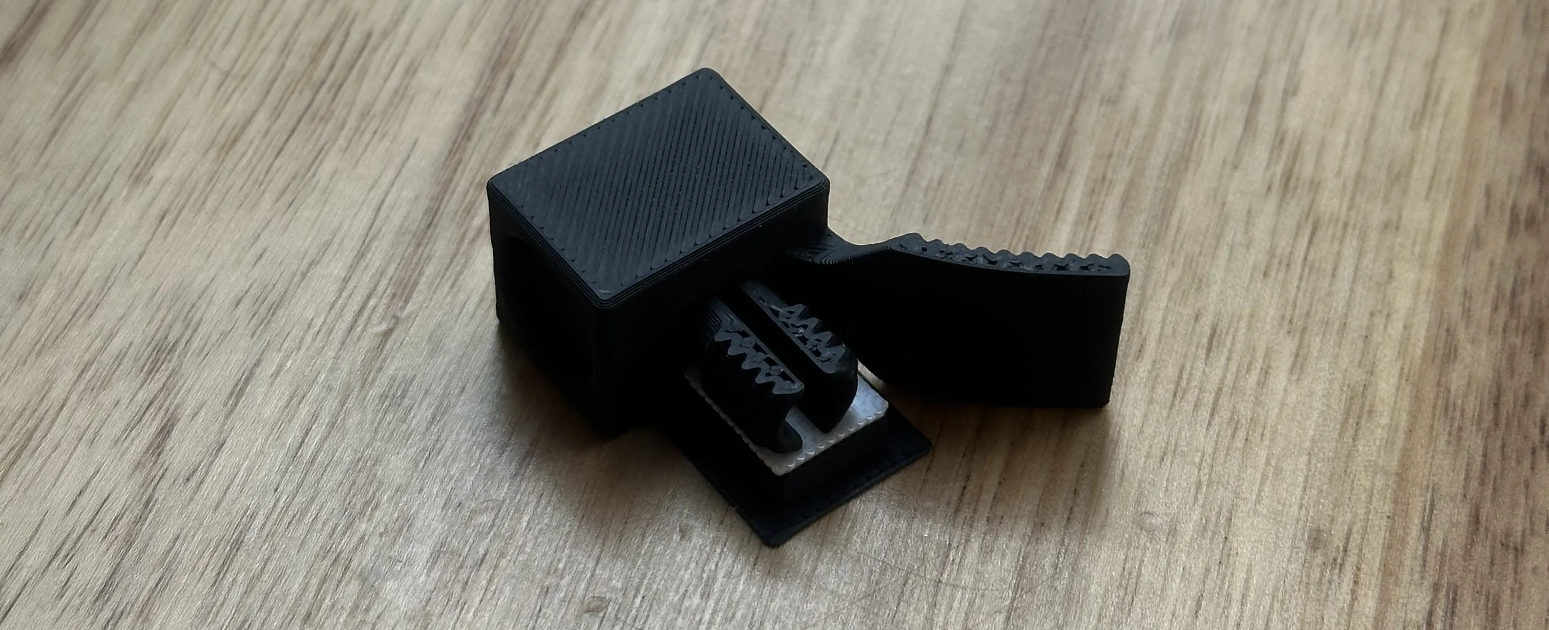
I highly recommend using these types of supports for technical parts.
I do NOT care so much about how the supported surfaces look,
this is much more about the structural stability of the first layers above the supports.
If you want to use regular supports, please set this correctly in Bambu Studio, not Bambu Handy!
The dual nozzle system works like a charm for support interface materials. With no mixing of model and interface material in the nozzle, those supports come off very easily as one piece!!
The plate with the lettering parts contains the letters A-H. Just remove the ones you don't need!
##########################
###### MATERIAL CHOICE ######
##########################
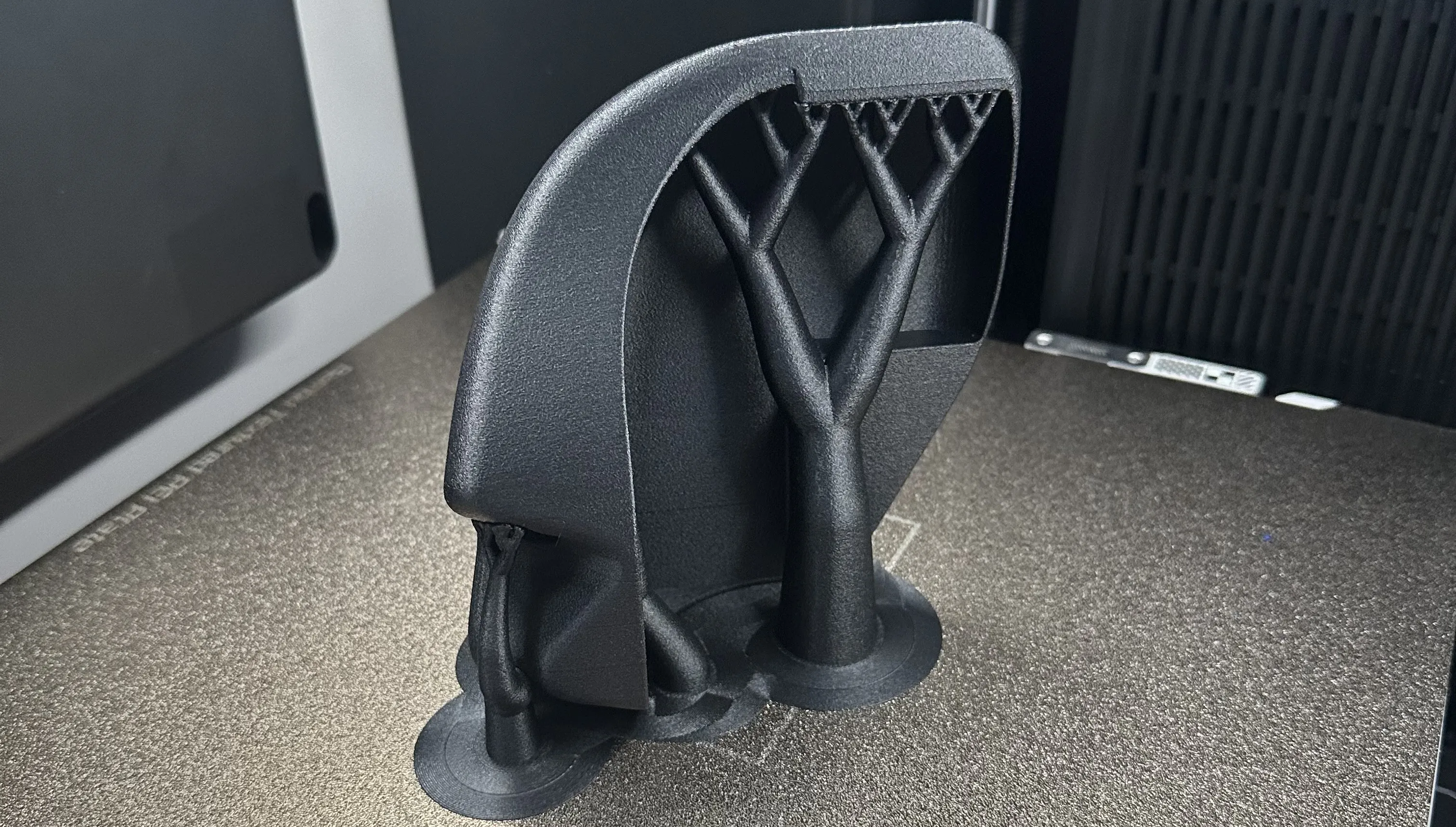
I chose ABS-GF for most of the parts for a few different reasons (PETG would have been my second choice):
The units are mounted to a printer with a 65 degree C chamber heater. The printer can get quite hot on the outside. This material can withstand that without losing its shape over time. This mainly applies to the holder, as the other parts will not have direct contact with the machine (i used PLA for the couplings, housing and nuts!)
Especially for the switching hub, I wanted a material with a hard surface, so it will not be „eaten away“ by abrasive materials in a short period of time.
ABS-GF has outstanding performance on extreme overhangs - much better than regular PLA in my personal experience!
There are several overhangs in these prints, that really push the material used to its limits.
It also just looks great, the glass fibers make the layer lines almost invisible!
If you never tried CF or GF filaments, you will be amazed by how manufactured the printed parts look.
Take a look at the reactions to my H2D poop chute upload, which is also printed from this material. I just love it!
Please Bambu if you read this, give me more colors of it :D and rethink if you really want to discontinue yellow and green :((
######################
####### ASSEMBLY #######
######################
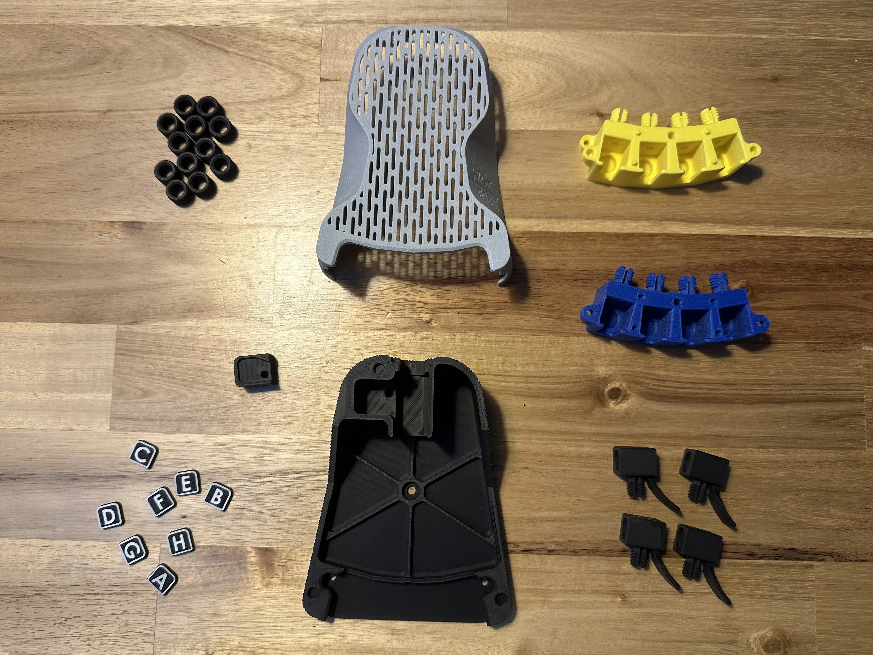
(this pictures shows the parts for Module B)
____________________________________________
***** MAGNETS INSTALLATION *****
This is the part of the build that you have to be most cautios so you don't make a mistake!
The magnets in the individual slots and letttering elements must all be oriented the same way. Otherwise, the module will not work.
The slots must also all have the same polarity so that the magnetic labels can be attached anywhere.
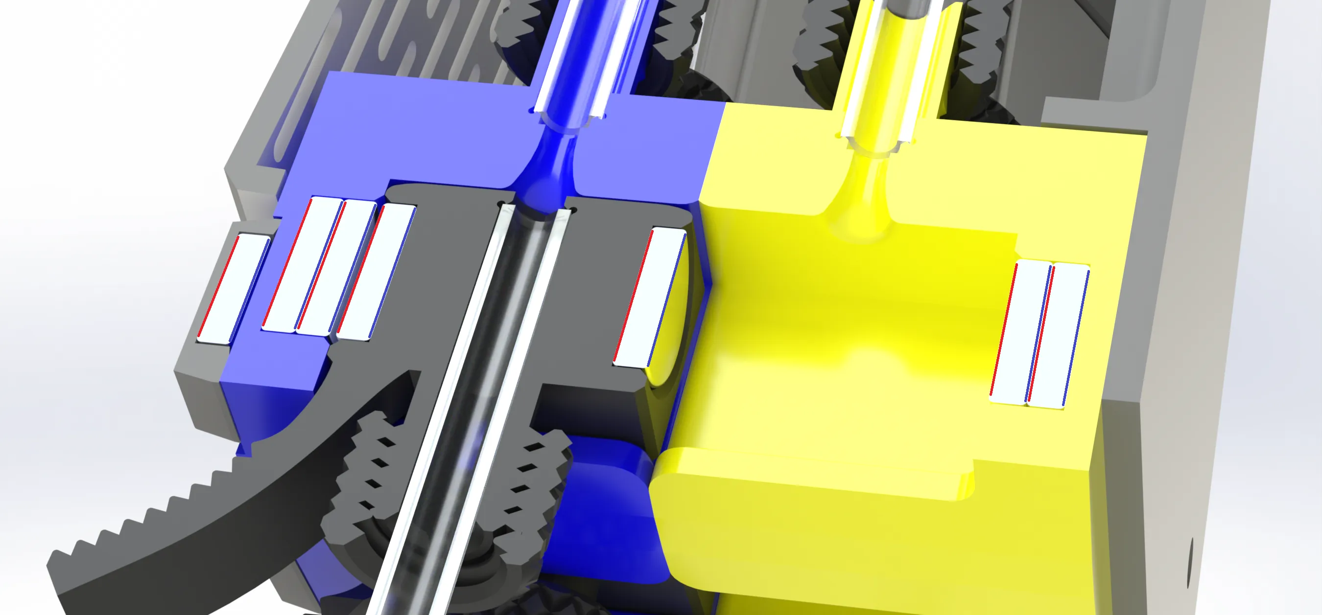
And you might have guessed it, if you are planning to use one of the more extensive versions (8 or 12 AMS),
The modules should also be all the same.
I decided to glue in all magnets that are used. You might ask yourself, why i did'nt use pressure fits.
Actually, if I did this only for myself, i would have done so.
Not every printer runs the same. So a pressure fit that works for each and everyone of you, is hard to accomplish.
You might even find, that you will not need to use glue on some of the holes in this model as they are, depending of how well your printer is dialed in.
Not every filament acts the same when it melts and cools down again.
But enough of this, lets get to assemble this!!
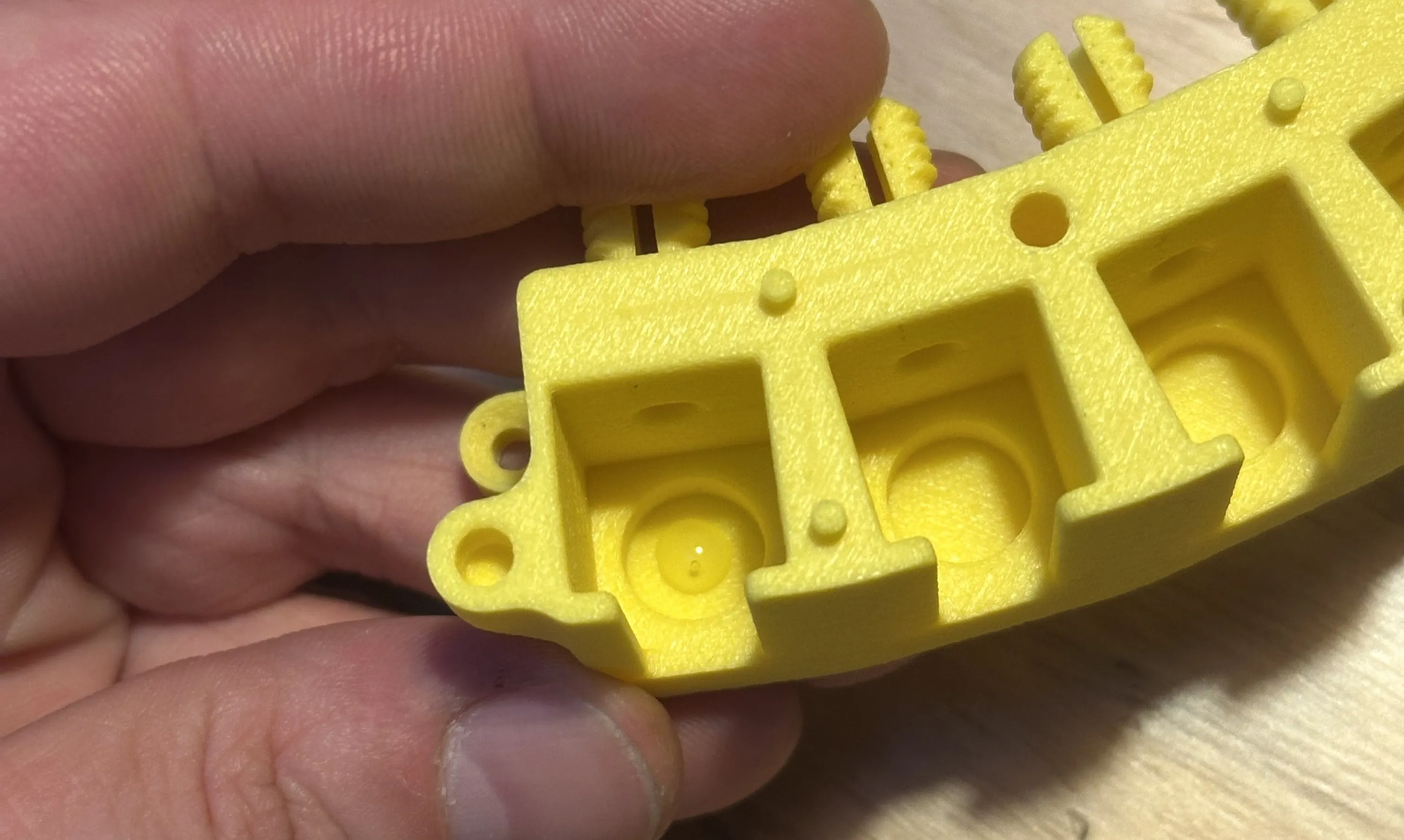
A drop of this size from high viscous super glue is what you want before you press in the magnets.

Each Pocket gets two 10x2mm magnets, stacked on top of each other. I like to use a flat screwdriver and attach the magnets to it for installation like this:

Make sure that you spread the access glue that is pressed through the gaps to not leave back any high spots on this surface, as that could cause problems with the couplings sitting slightly offset, making the tube interface non concentric anymore!
I recommend completing one slot first, keep in mind the the two halfs of the internal hub go on top of each other in later assembly steps.
So if the parts are lying on your workspace like in the following picture, the magnets need to be the opposite direction!
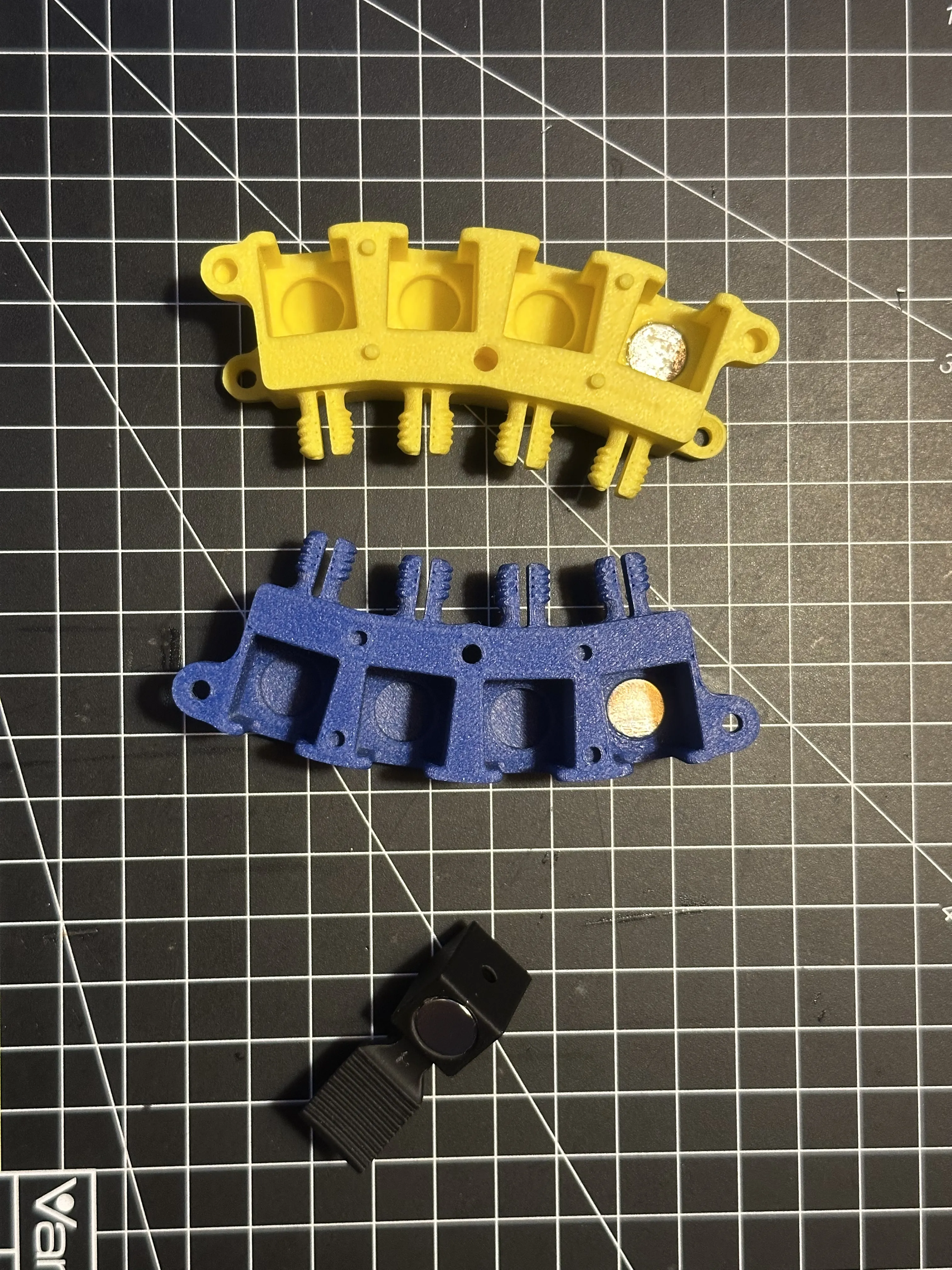
Each coupling also needs two 10x2mm magnets. One per side.
The lettering tabs get one 8x2mm magnet each:
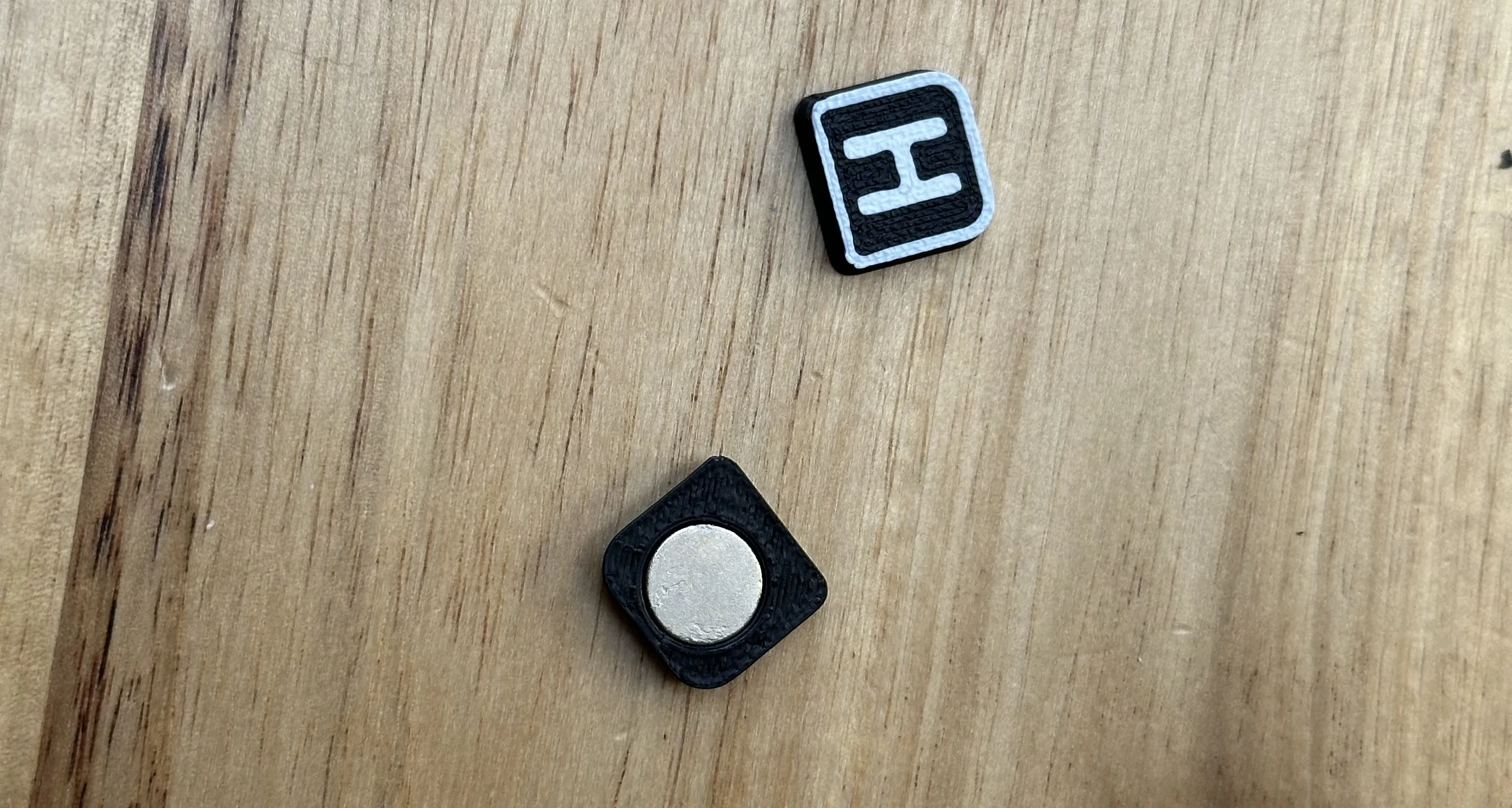
Check whether you have done your previous work correctly!
If so, you can proceed to complete the parts one after the other by filling all the pockets with magnets, while always making sure that they are installed the same way as the others in the respective part.
The housing and cover of the modules is held together by six 5x3mm magents. again, making sure they are placed in the correct orientation!
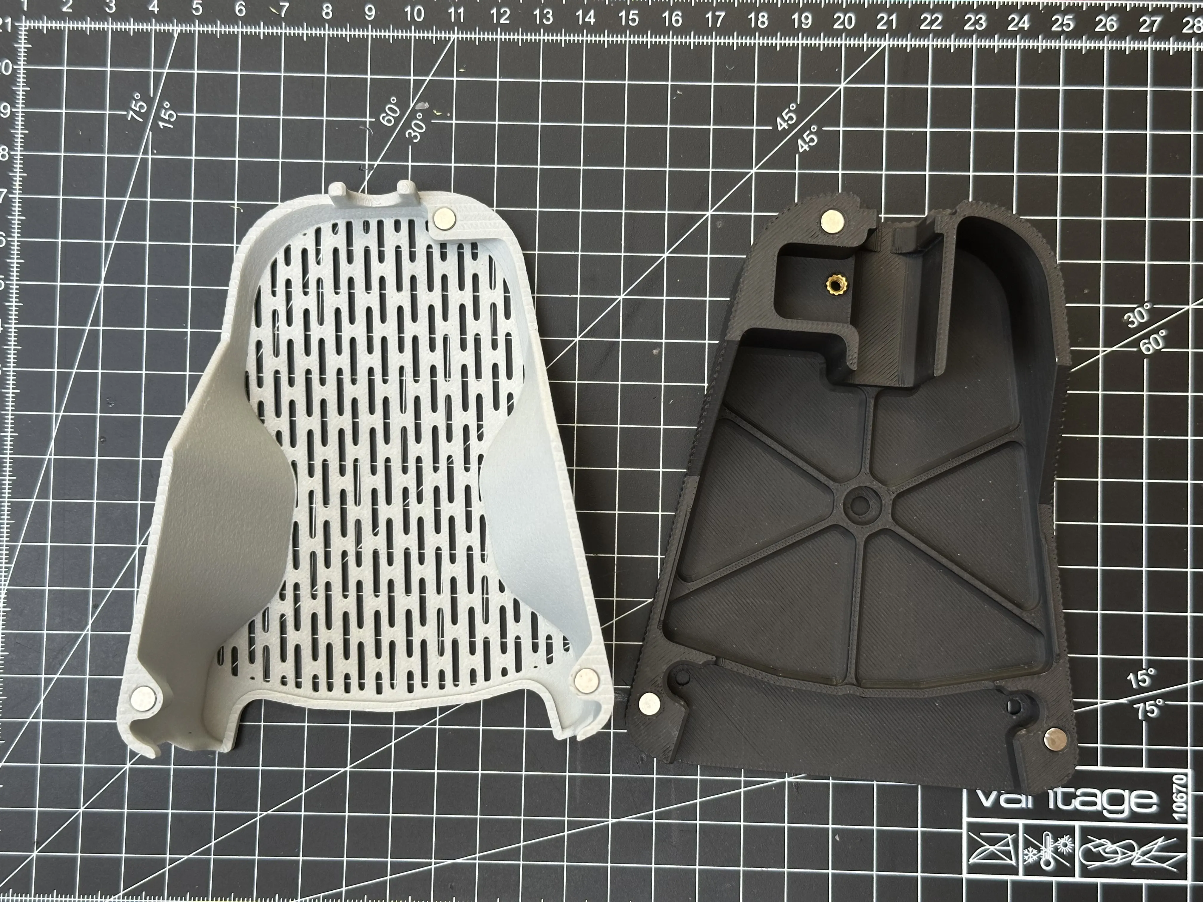
____________________________________________
***** CLEANING OUT THE PATH*****
also a VERY important step, don't skip this!!
I did not wan't to use the “tear drop shaped hole" method here, as it would have exposed the top section of beginning of the PTFE Tube
that exits the interface of the slots. Filament could have gotten stuck there. This needs a perfect circular funnel that directs the filament exactly to the center of the exit tube.
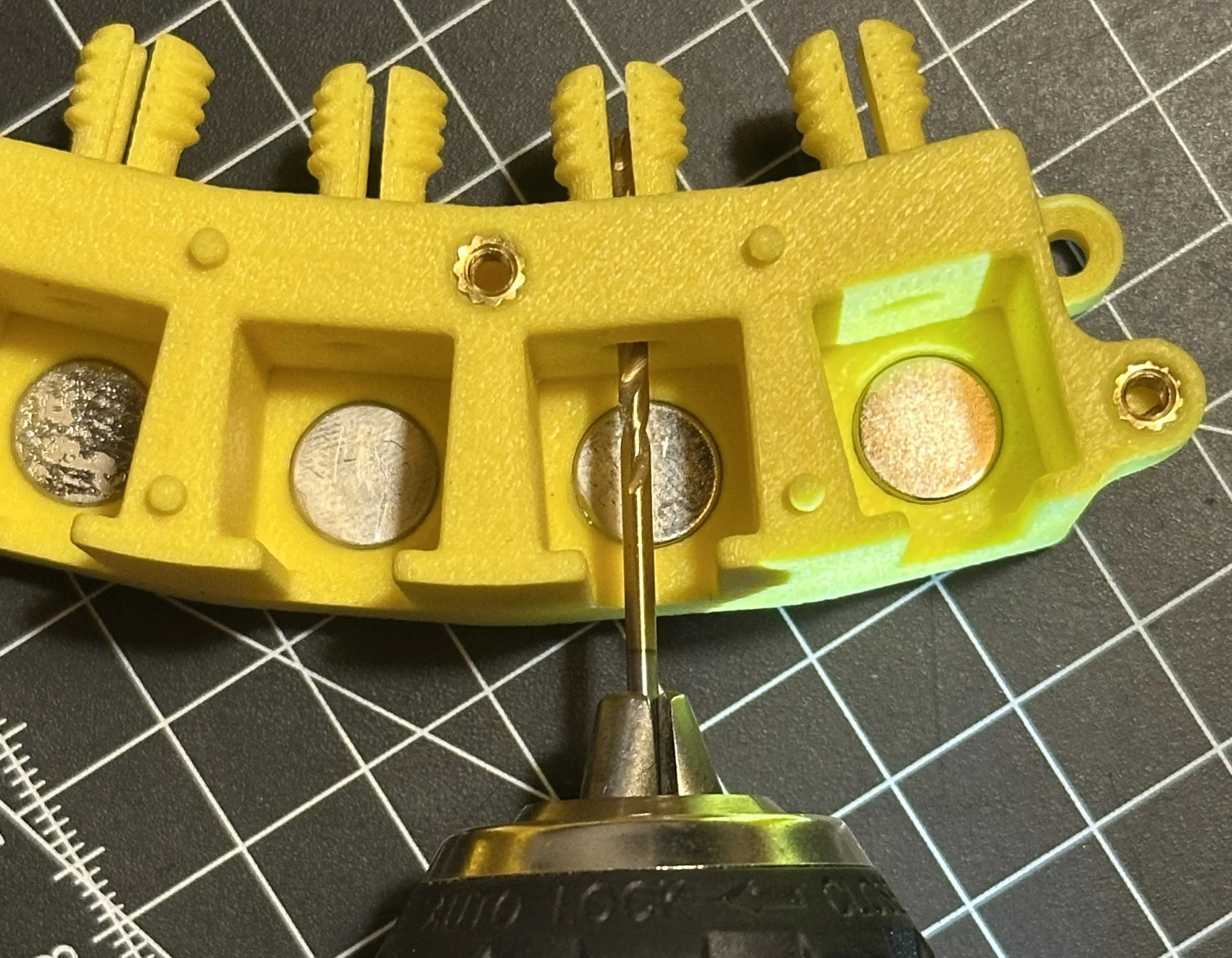
Use a 2mm drill bit and drill through all paths of both halfs of the hub once to correct the shape of the path.
Drilling through once is enough, don't overdo this!! Try to do this as straight as possible! (not like in this picture, sorry :'D)


____________________________________________
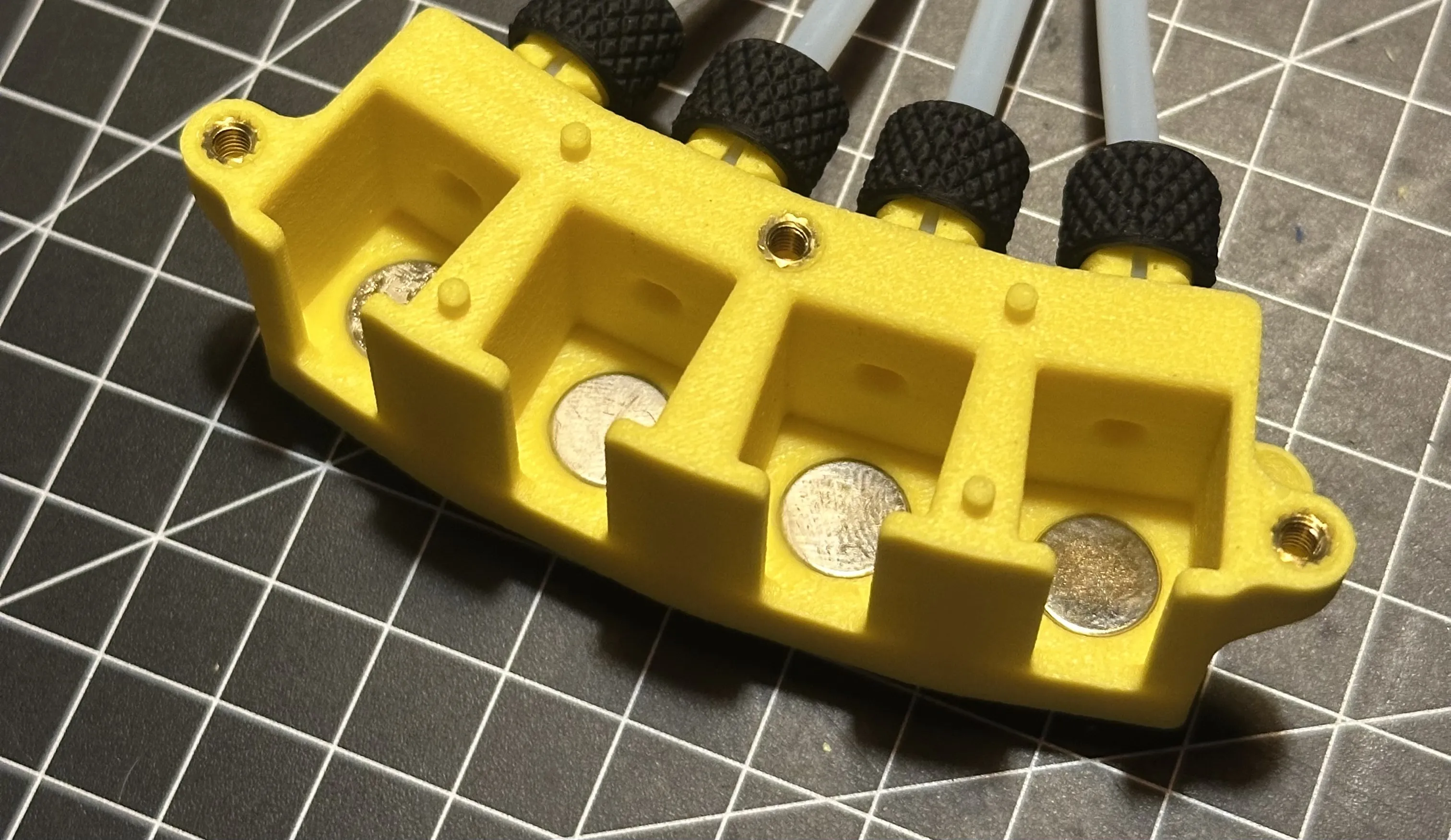
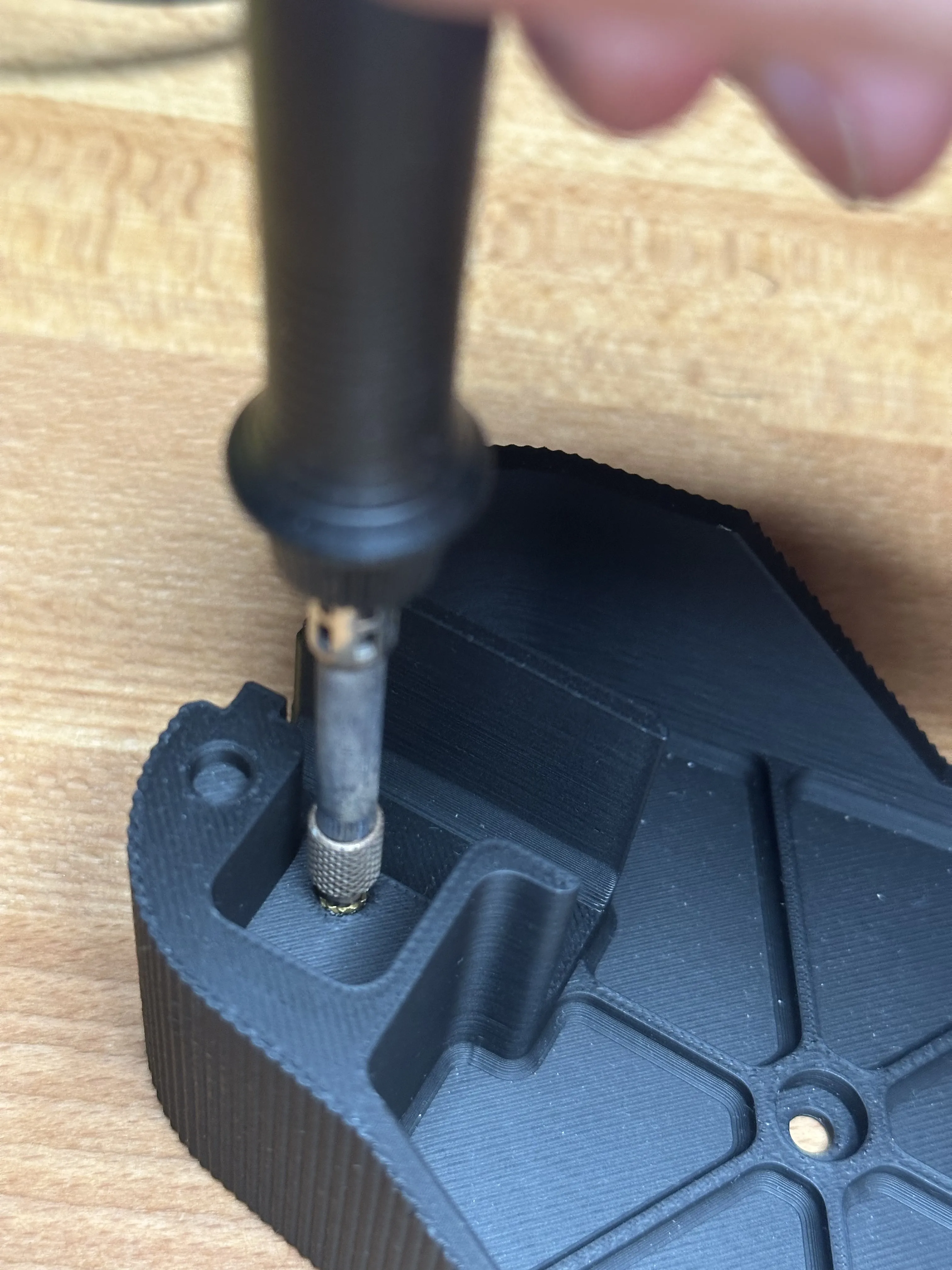
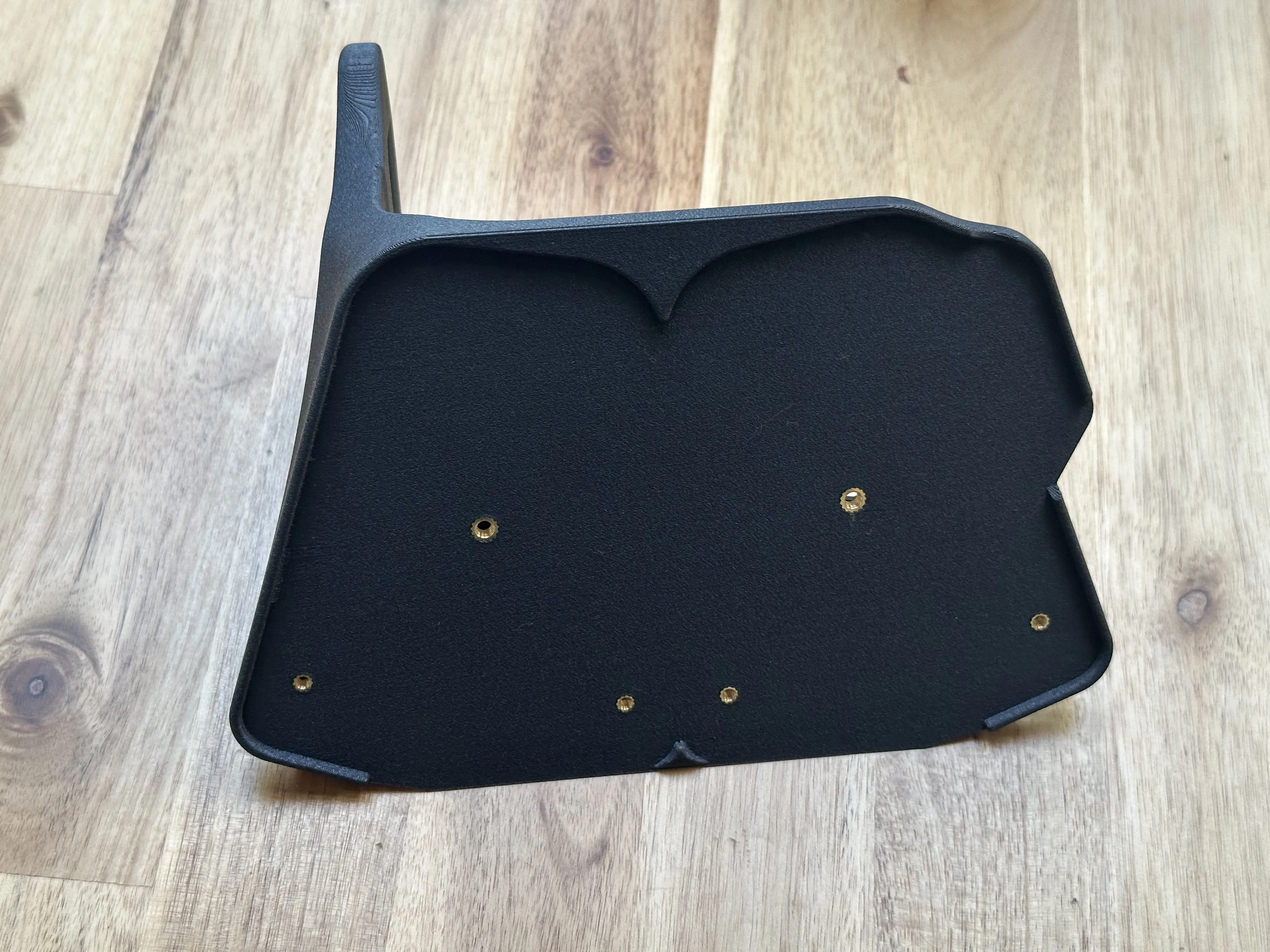
***** HEAT SET INSERT INSTALLATION *****
(If you do this for the first time, i recommend watch a tutorial on youtube, there are plenty of good ones!)
You need to use a soldering iron to push them into the printed parts.
Please don't try to pound them in with a hammer as that would probably split the parts.

This half it the hub gets three M3 inserts.
One M3 insert is installed in the bottom part of the housing:
Each holder needs another two M3 and one M4 inserts (per module!!)
Last, if you want to use the input terminal model, press in two M3 inserts in these holes of the 4in1 adapters:
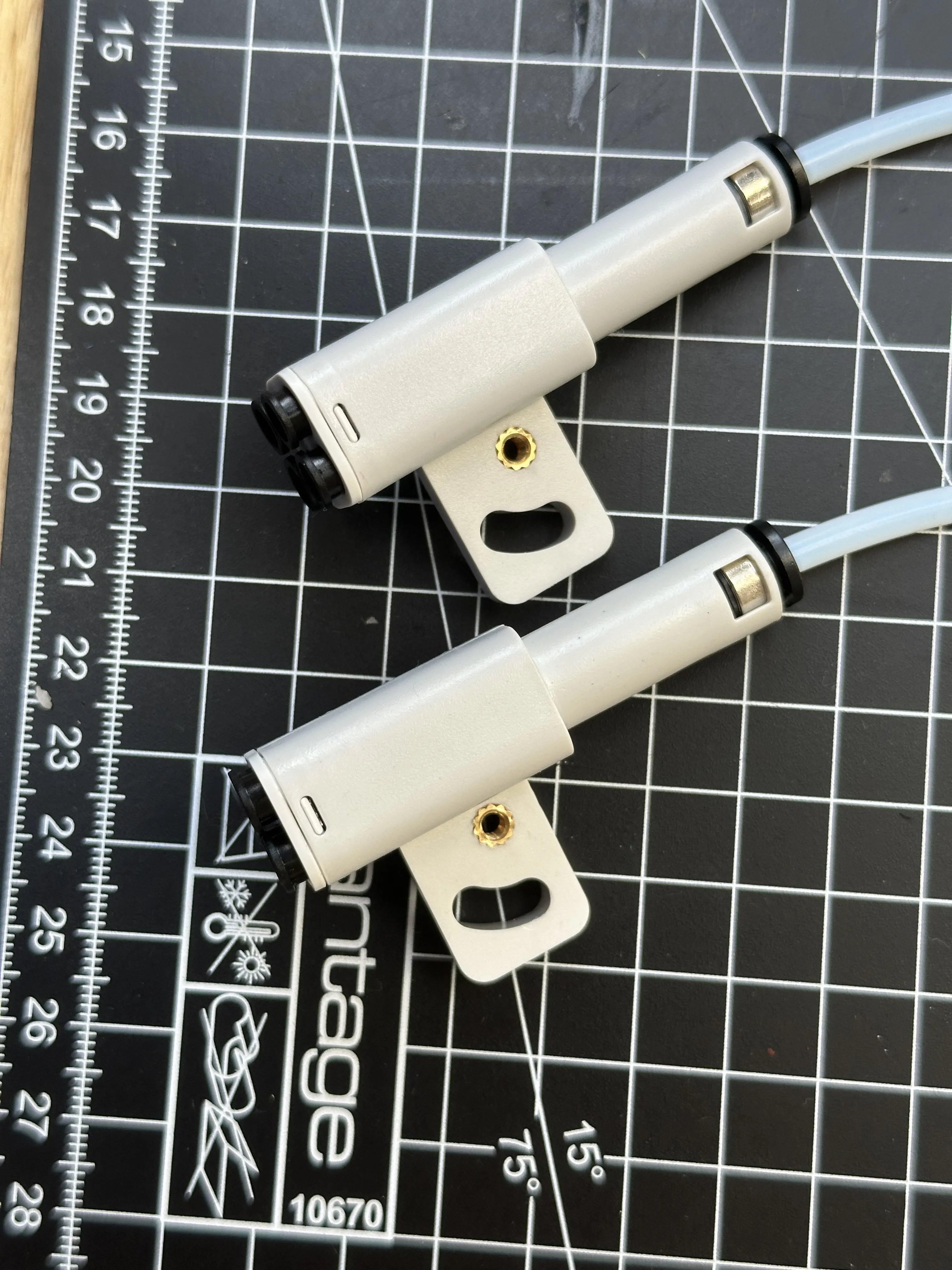
they are a fairly loose fit because the holes are a little bit wider than what you would typically use. But it is ok, the way they are mounted in the input cover, they only need to keep the adapters from sliding out a pocket.
____________________________________________
***** PTFE TUBE CUTTING (for the tubes inside the modules) *****
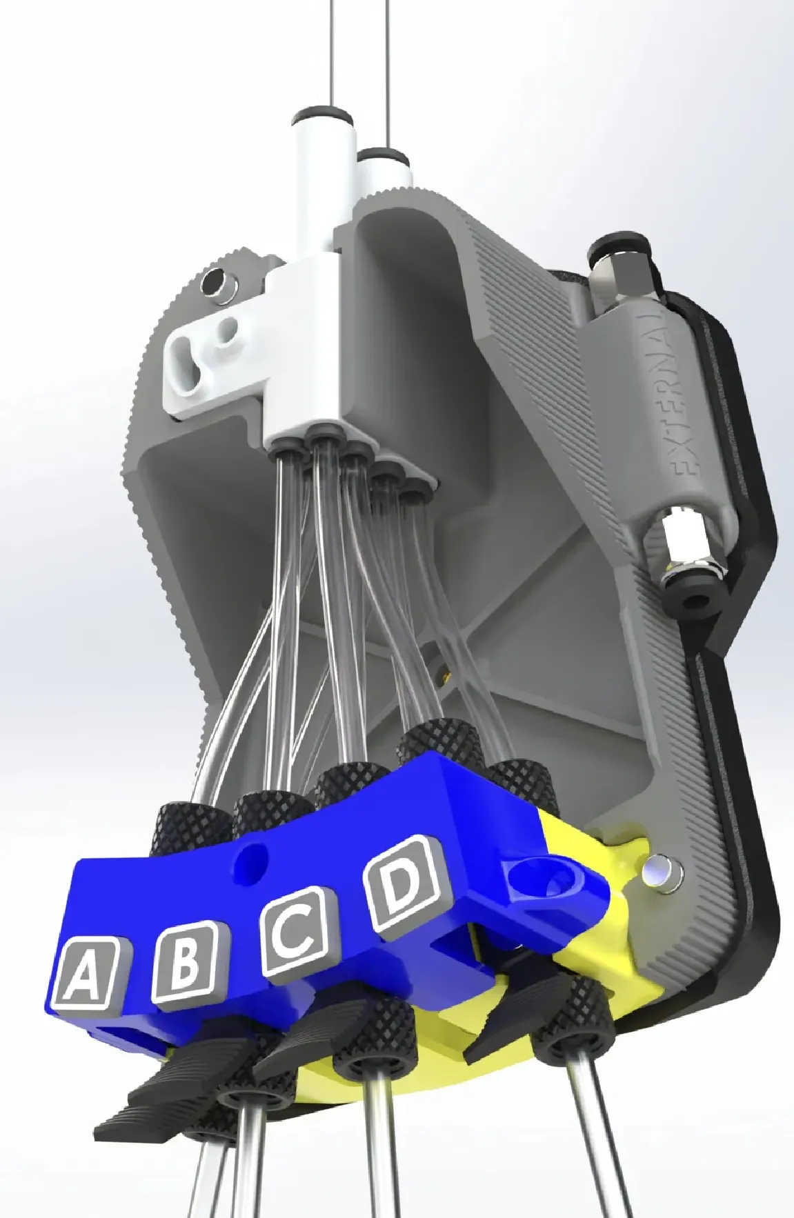

The outer four, more curved tubes, need to be exactly 80mm long.
The inner ones 78mm.
I added this little tool to the print profile list of this page, to make cutting a no-brainer!
____________________________________________
***** PUTTING EVERYTHING TOGETHER*****
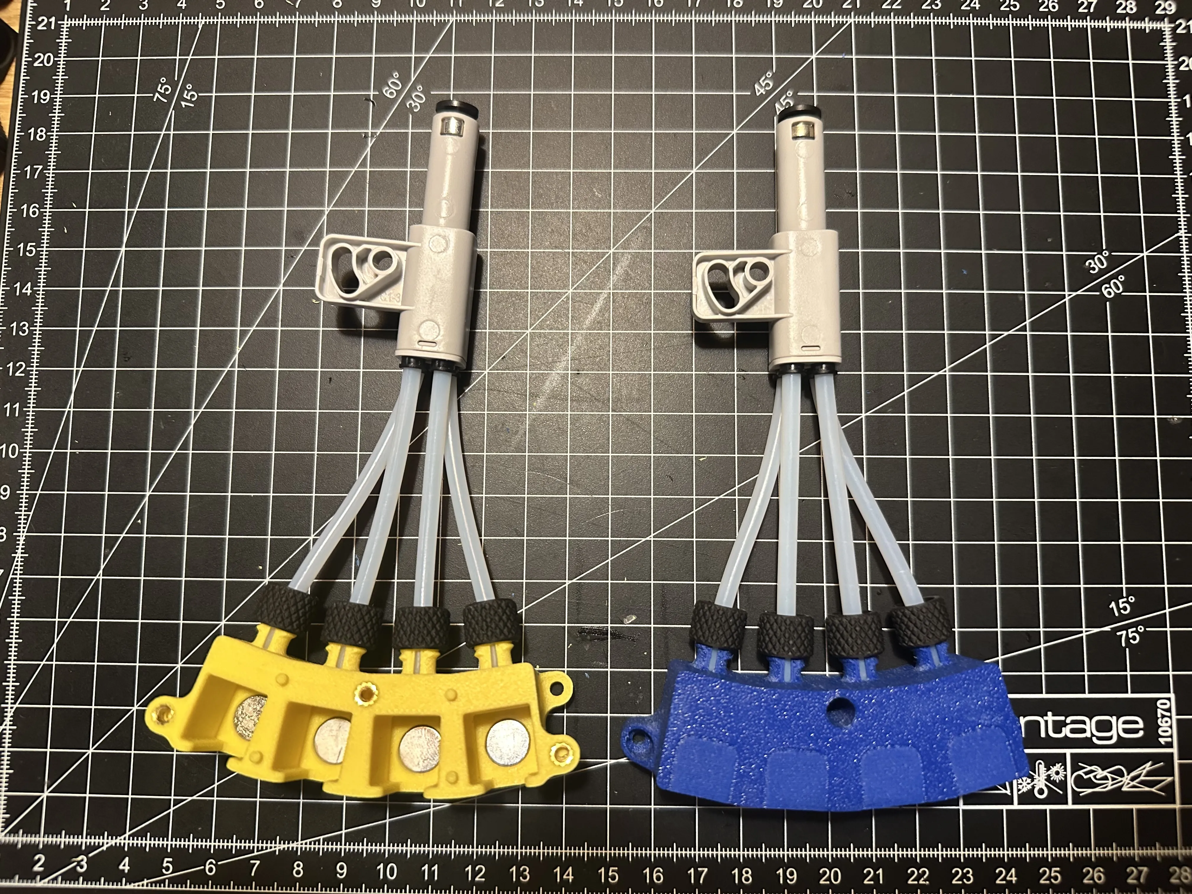
Install the pre-cut PTFE tubes on the two housing halfs.
Remember, the shorter ones go to the middle and the longer ones to the sides.
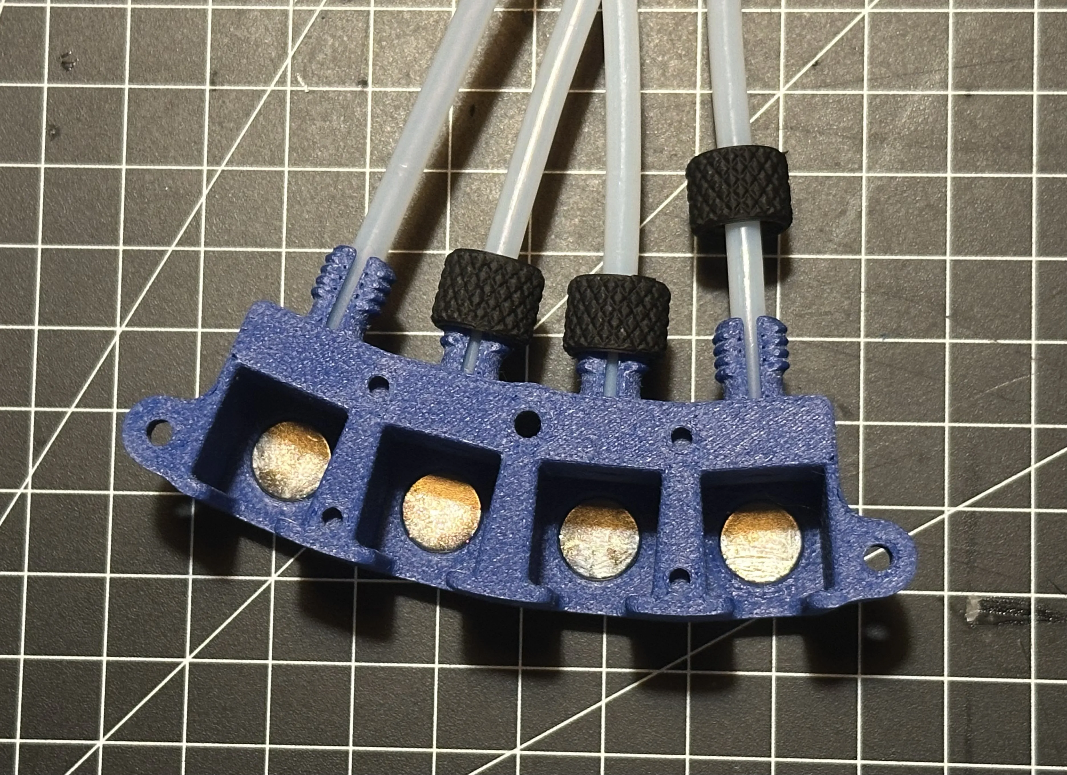
tighten them with the small nuts. The nuts are slightly conical. Pay attention to the orientation (bigger opening goes on the threads)
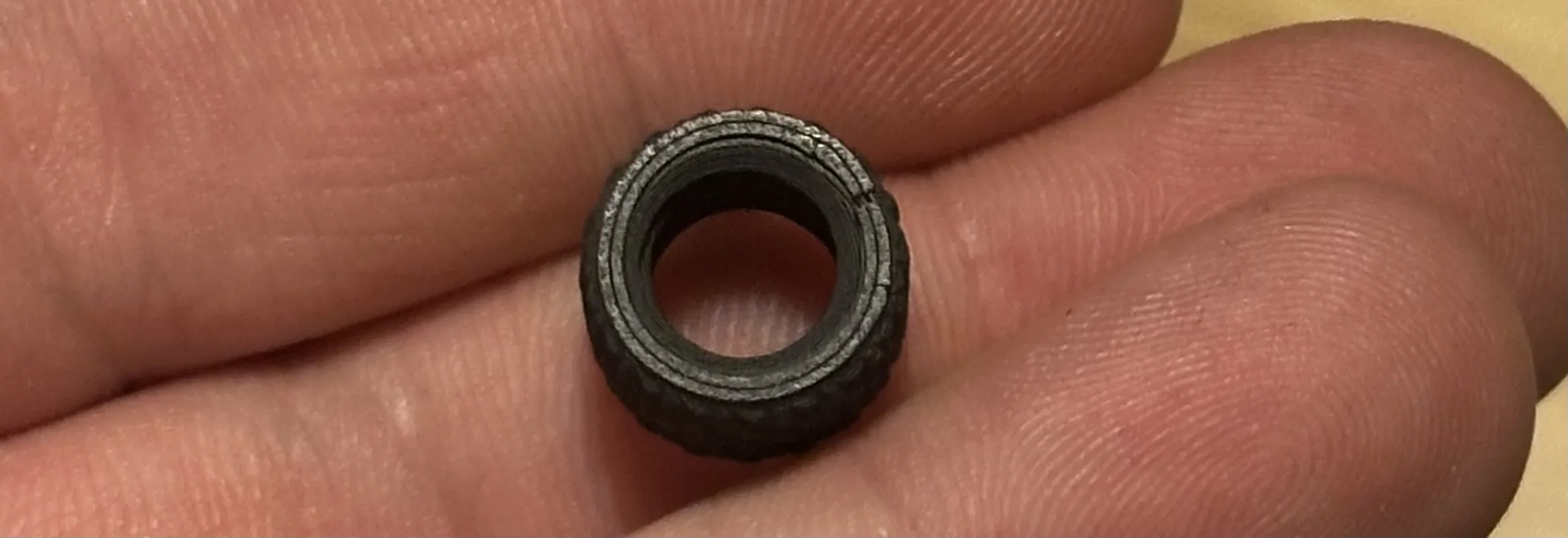
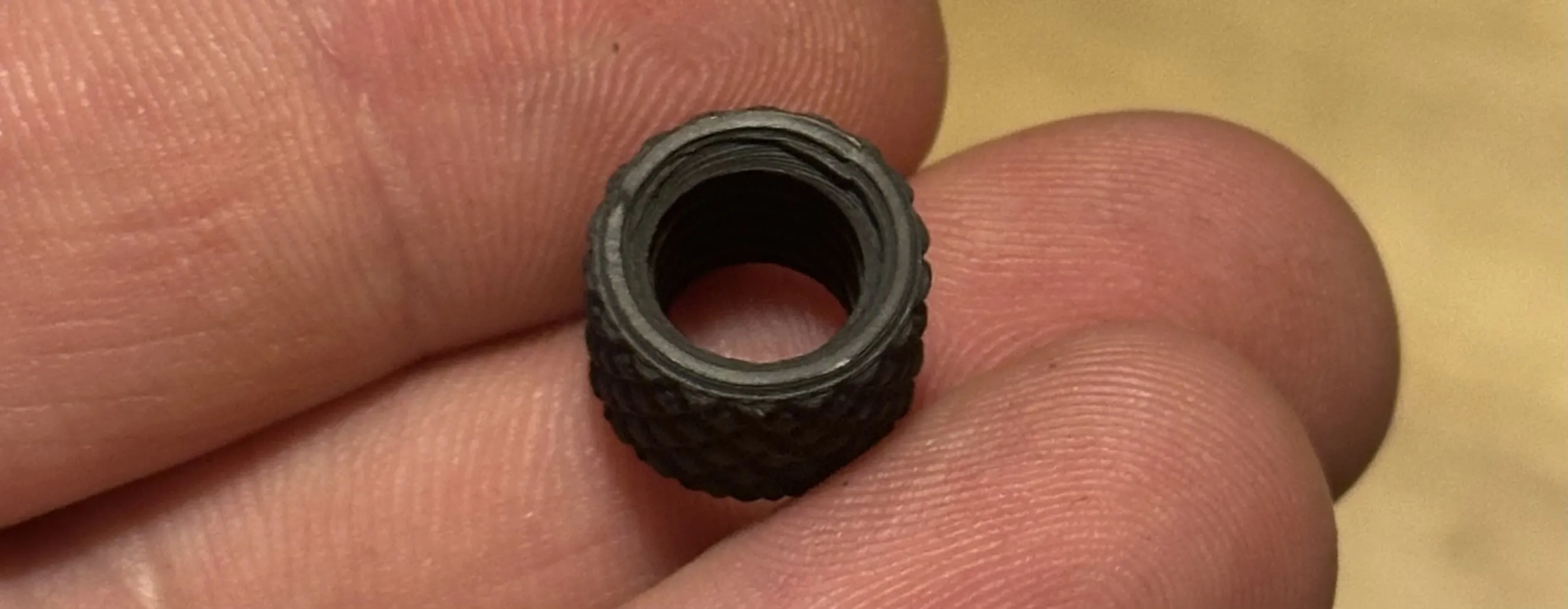
Perform this step for both sides.
After that, you can connect the 4in1s like this:
Install the couplings in the bottom part.
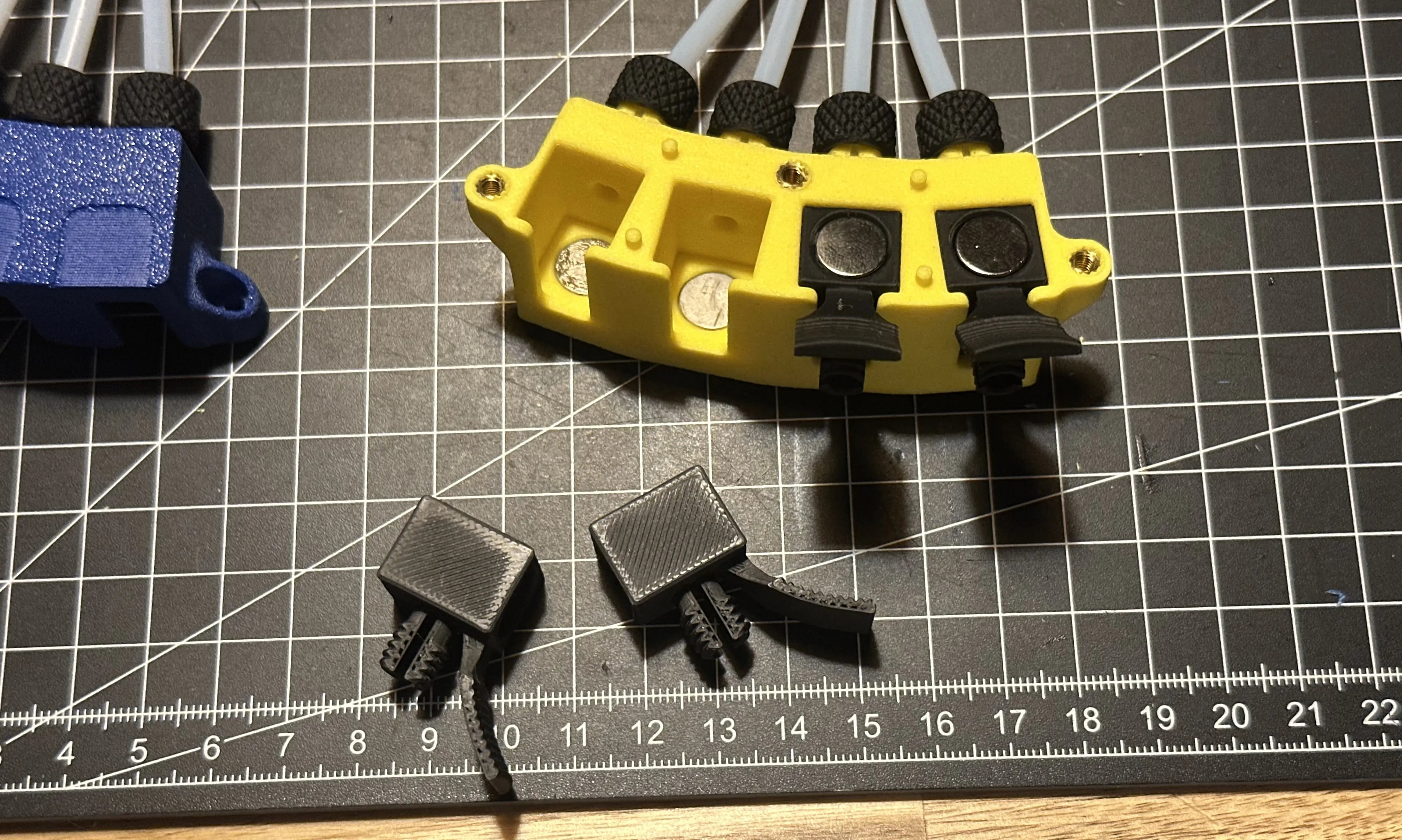
If they don’t slide in easily, you can rub their flat surfaces against the textured bottom layer of the hub:

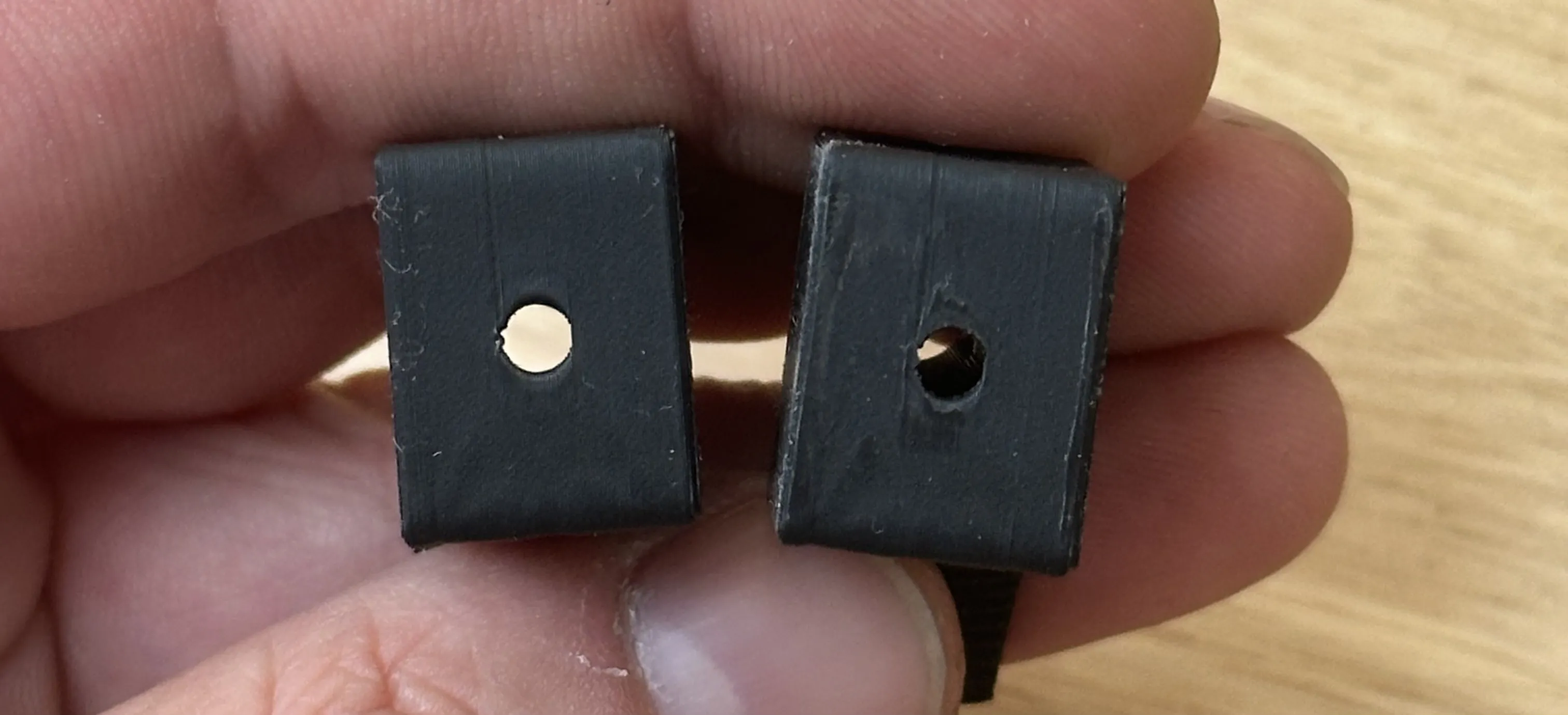
This works very to flatten some potential high spots.
(Left: before, right: after)

The couplings should slide in like this now:
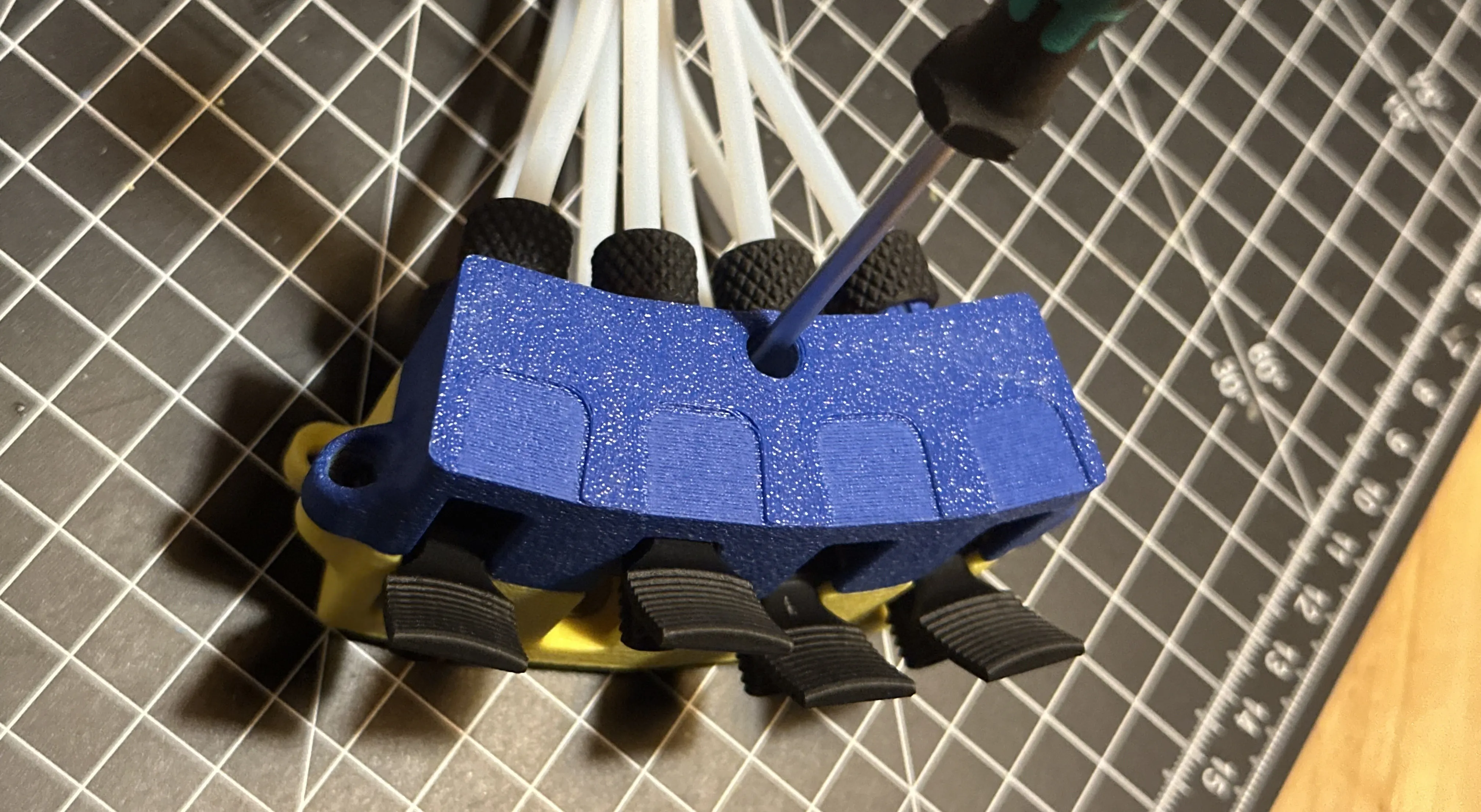
stack the two assemblies on top of each other and fix them with 3 M3x8 countersunk screws.
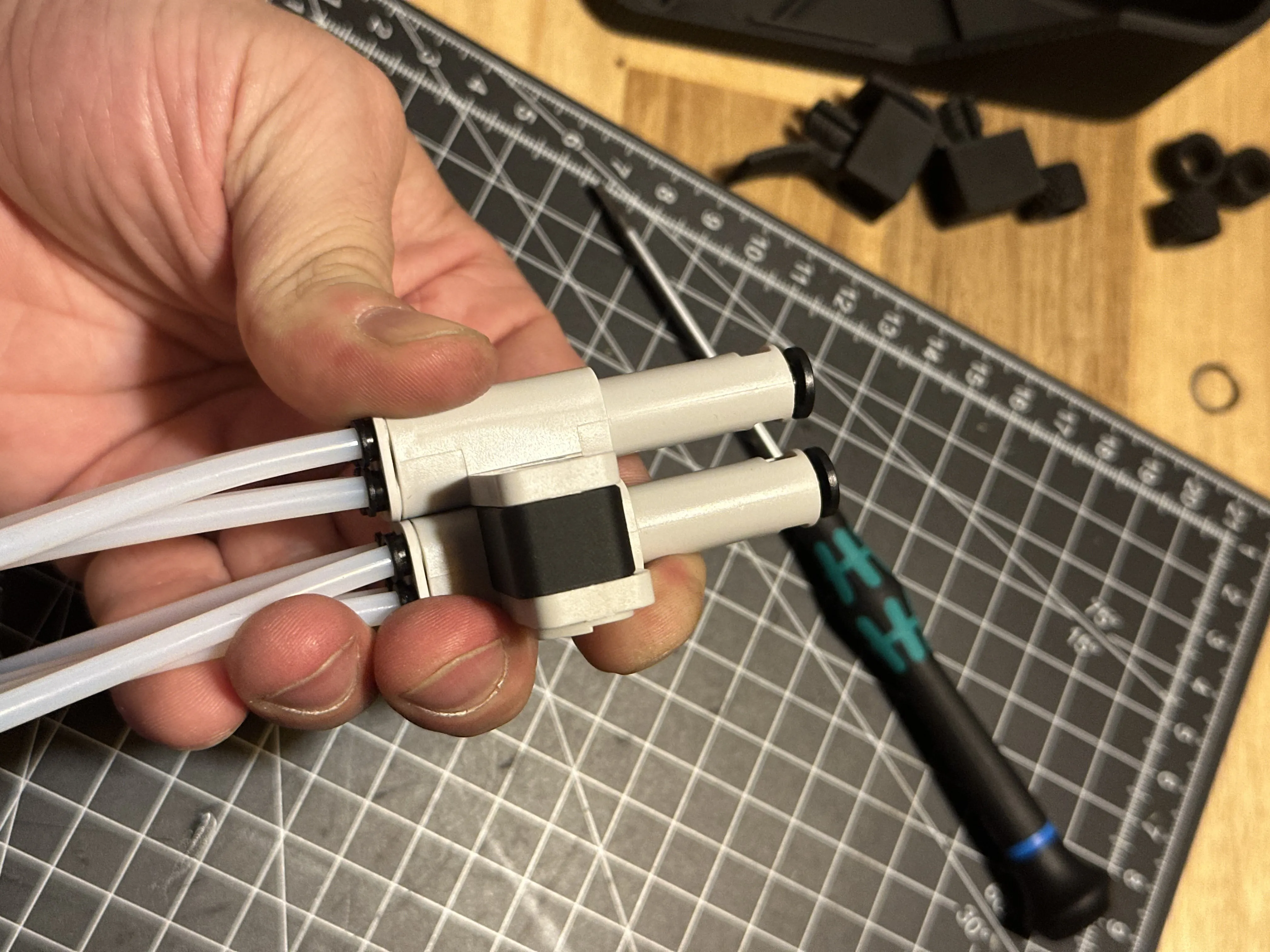
Slide the spacer between the 4in1 mounting tabs:
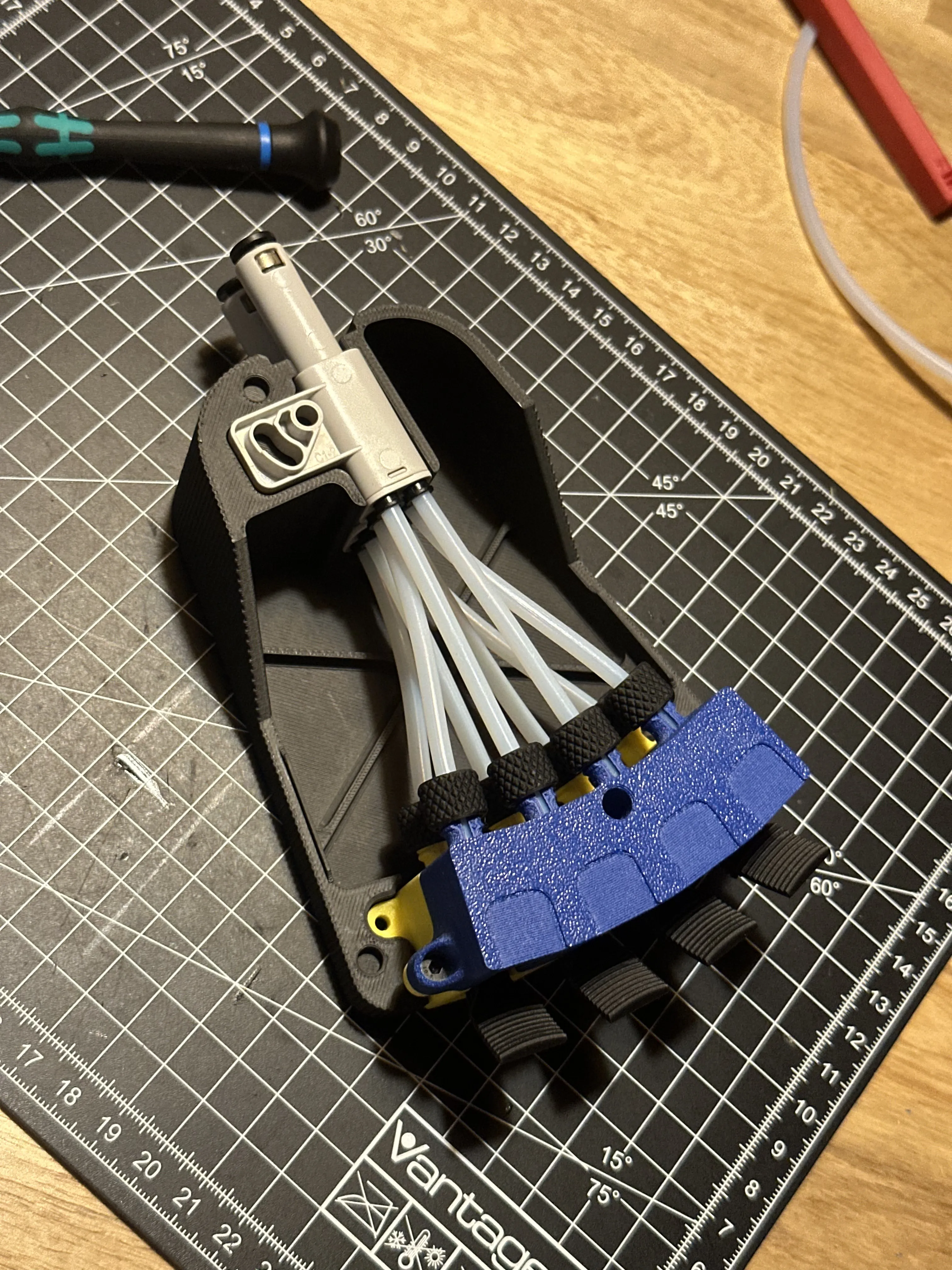
install the assembly in the bottom part of the housing:
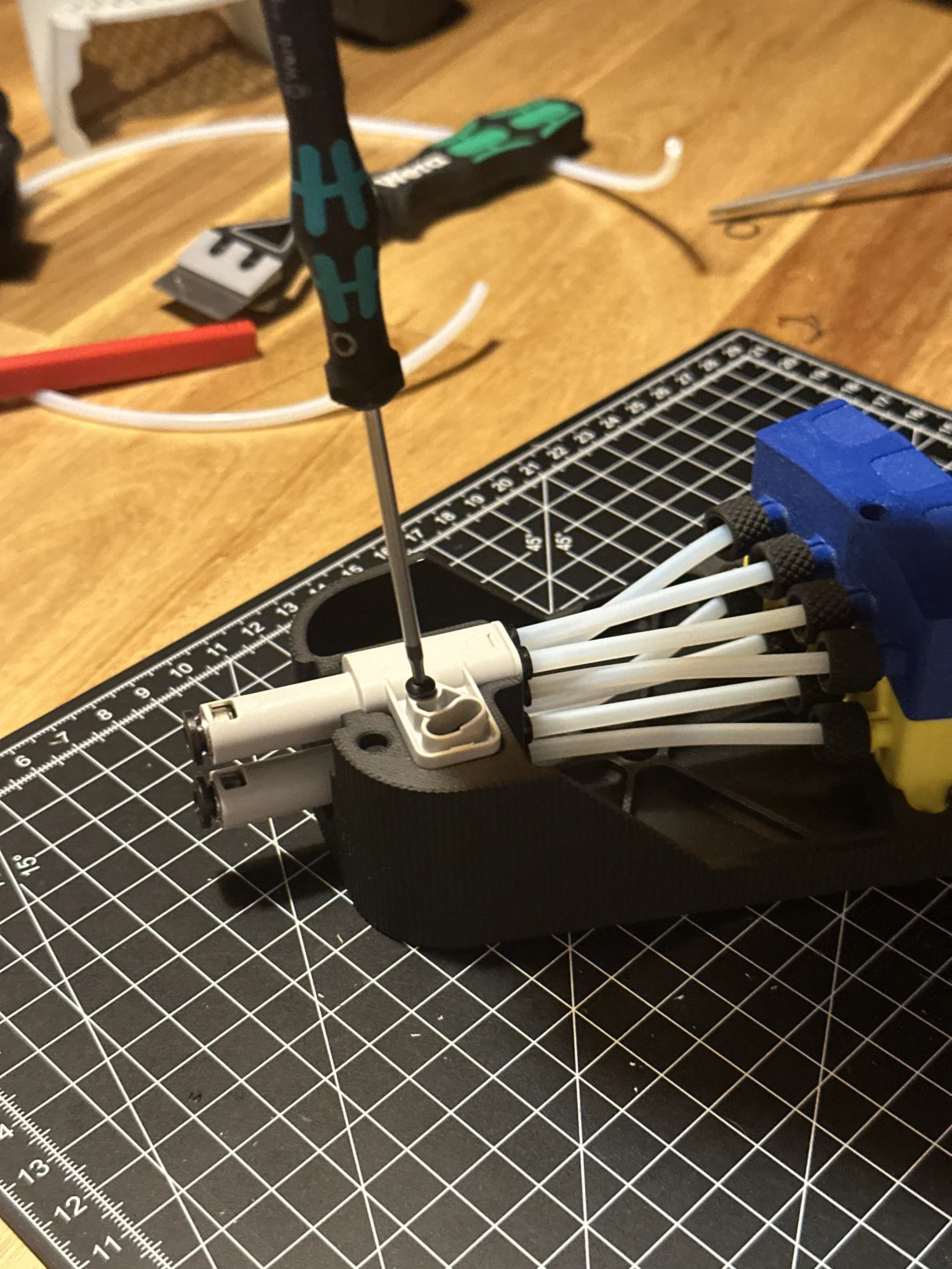
start with the adapters, then slide the hub in place in the cutout.
Fix the adapters with one M3x25mm buttonhead screw:
If you build a A Module, install the two PTFE tube fittings before the next step:
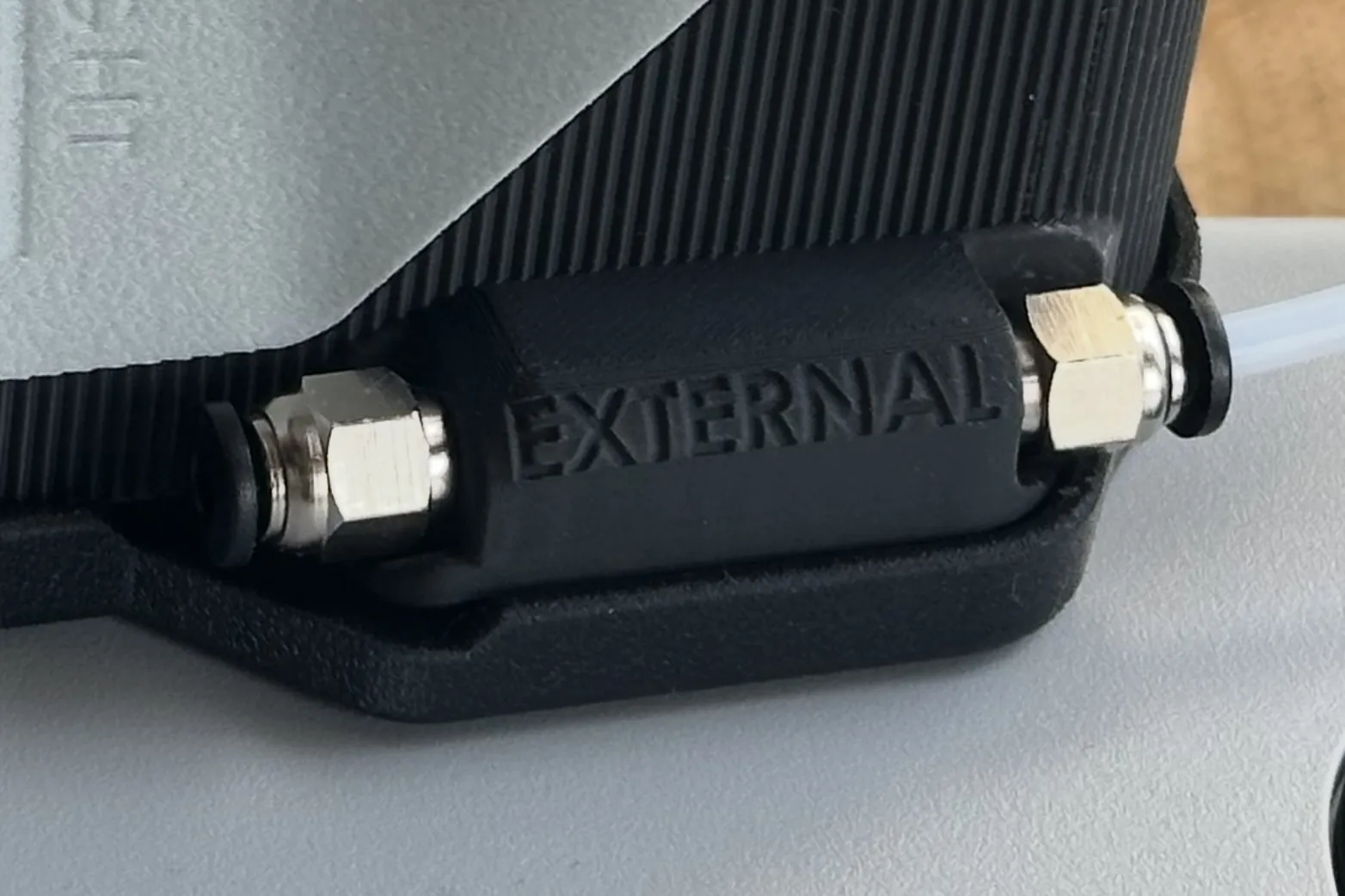
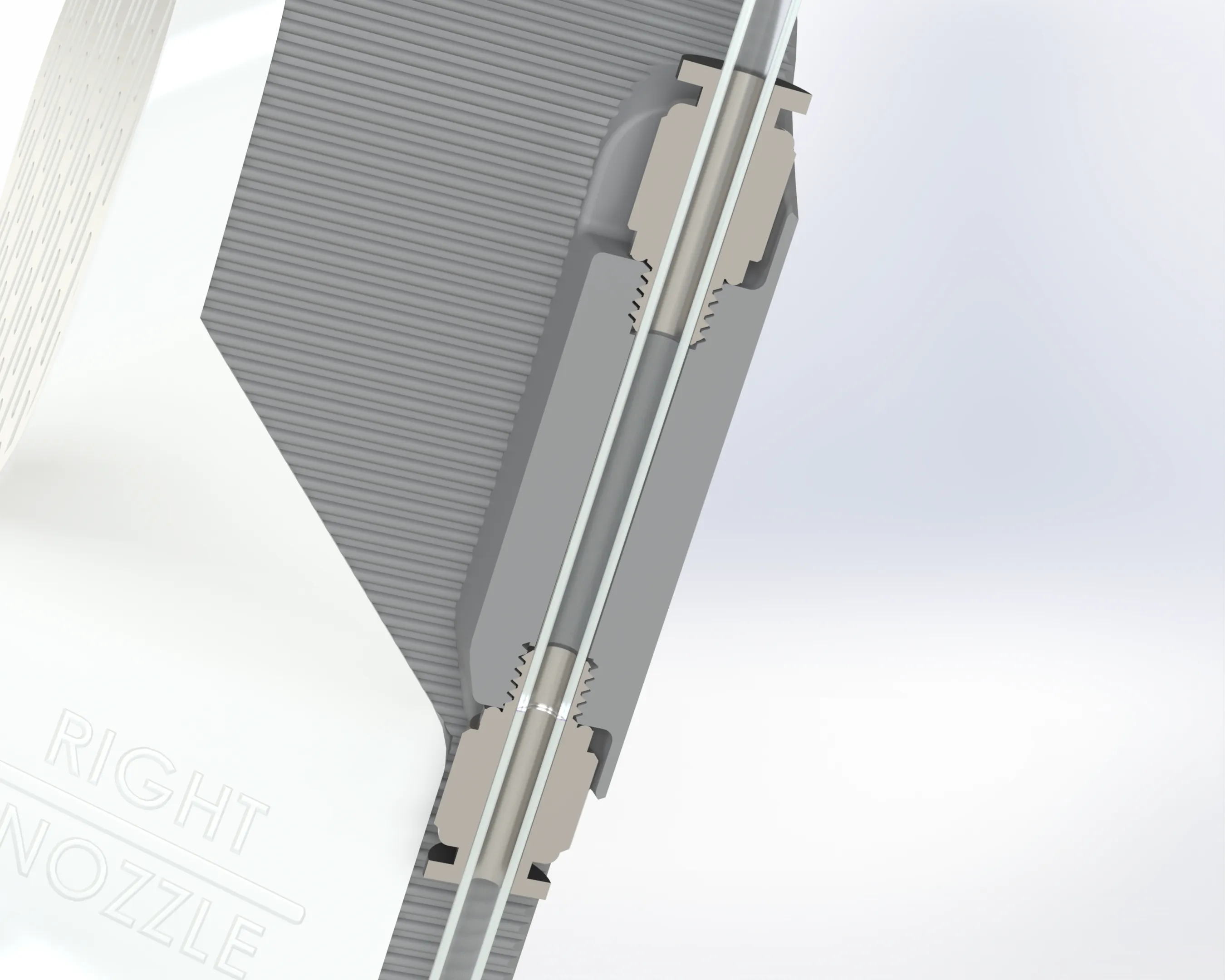
When you use this port, make sure the two PTFE tubes are pushed in so far, that they make contact to each other in the channel, for minimal resistance!
mount the holder on the printer (every version of the holder uses the same hardware):
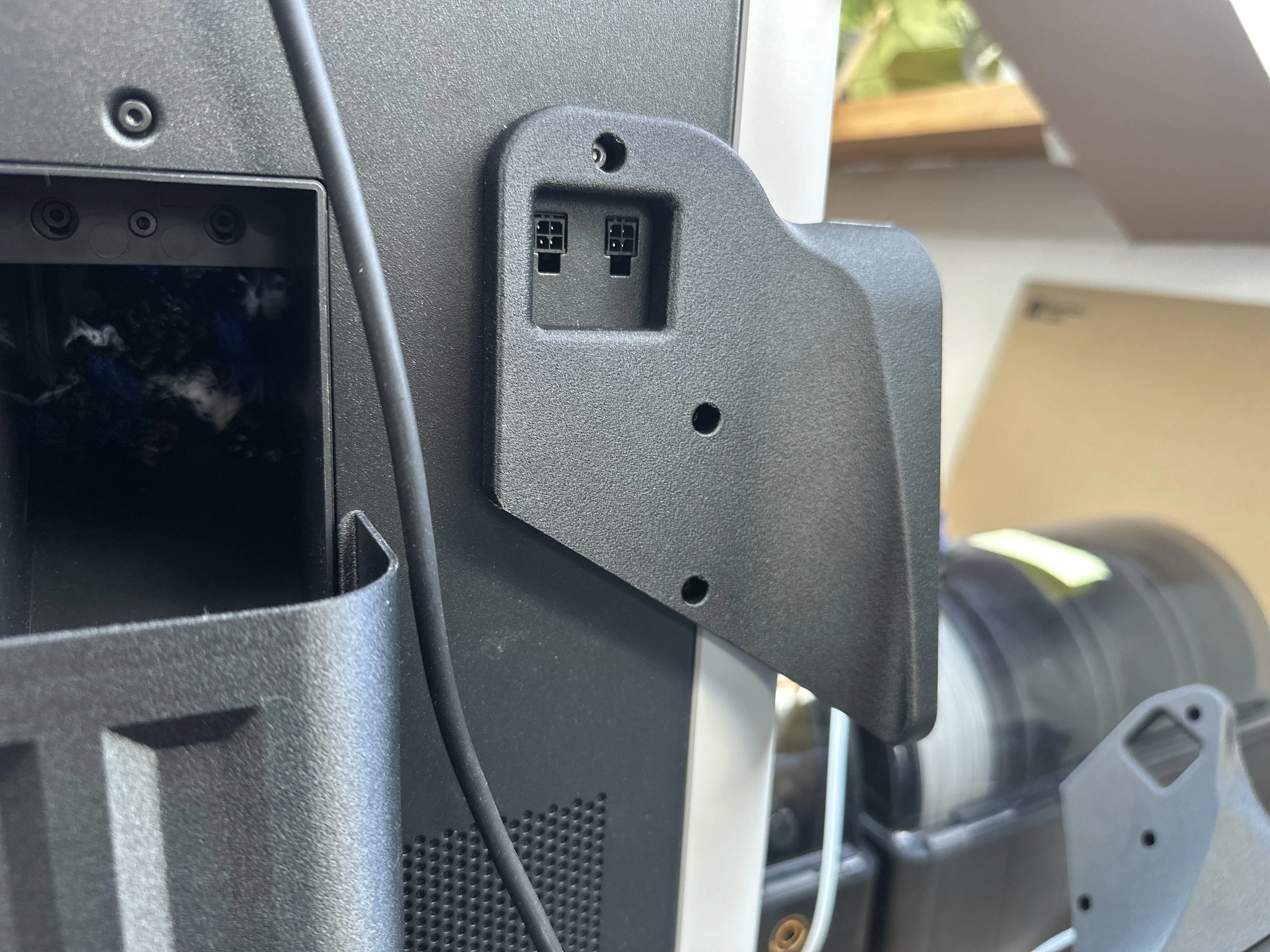
the top mounting point uses the stock screw of the printer.
The other two use M3x10mm button head screws. The screws must not be longer than 10mm!!
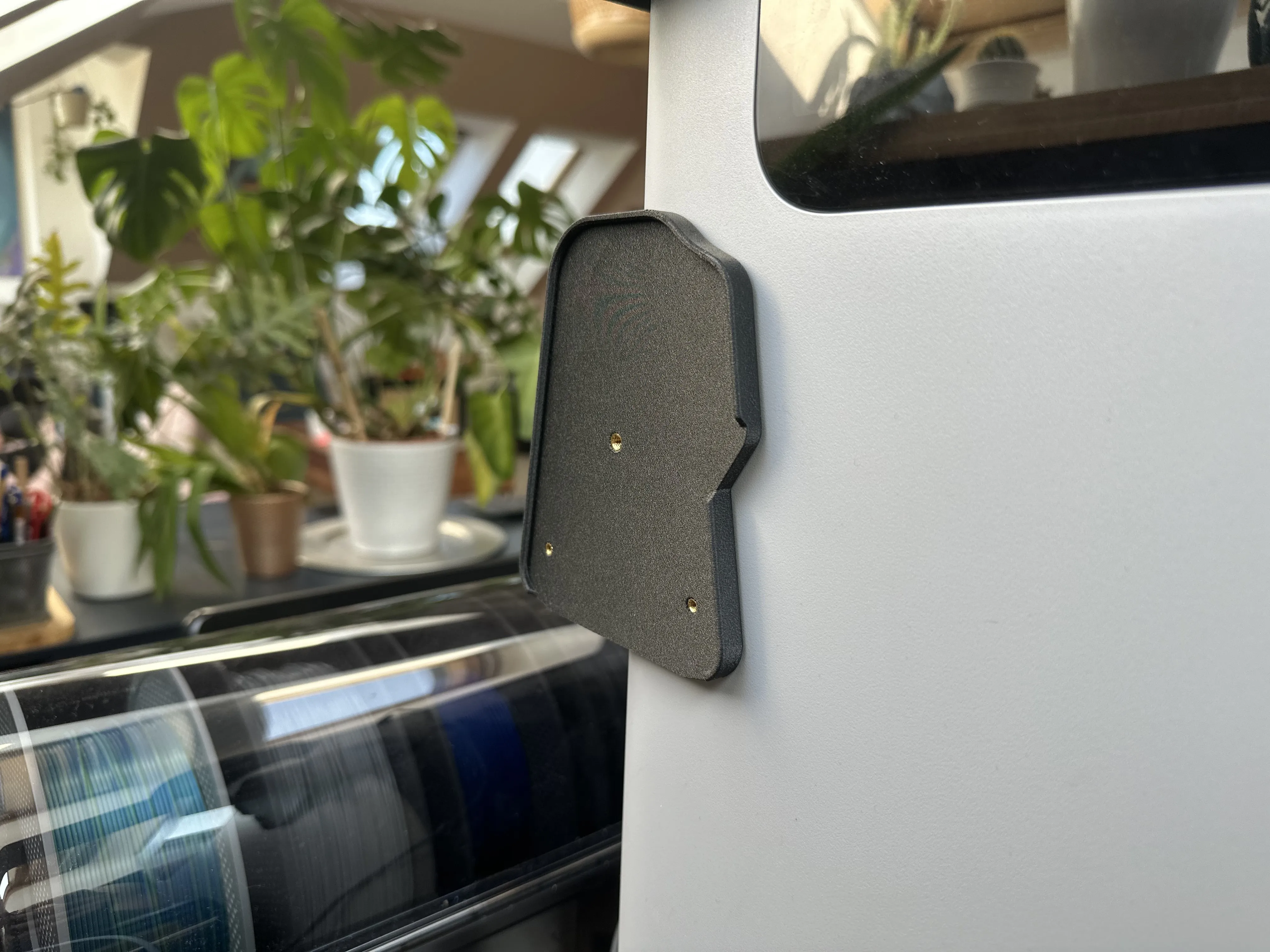
Install your number of modules on the holder and fix them with two M3x8mm countersunk and one M4x6mm button head screw.
Attach the magnetic lettering tabs:
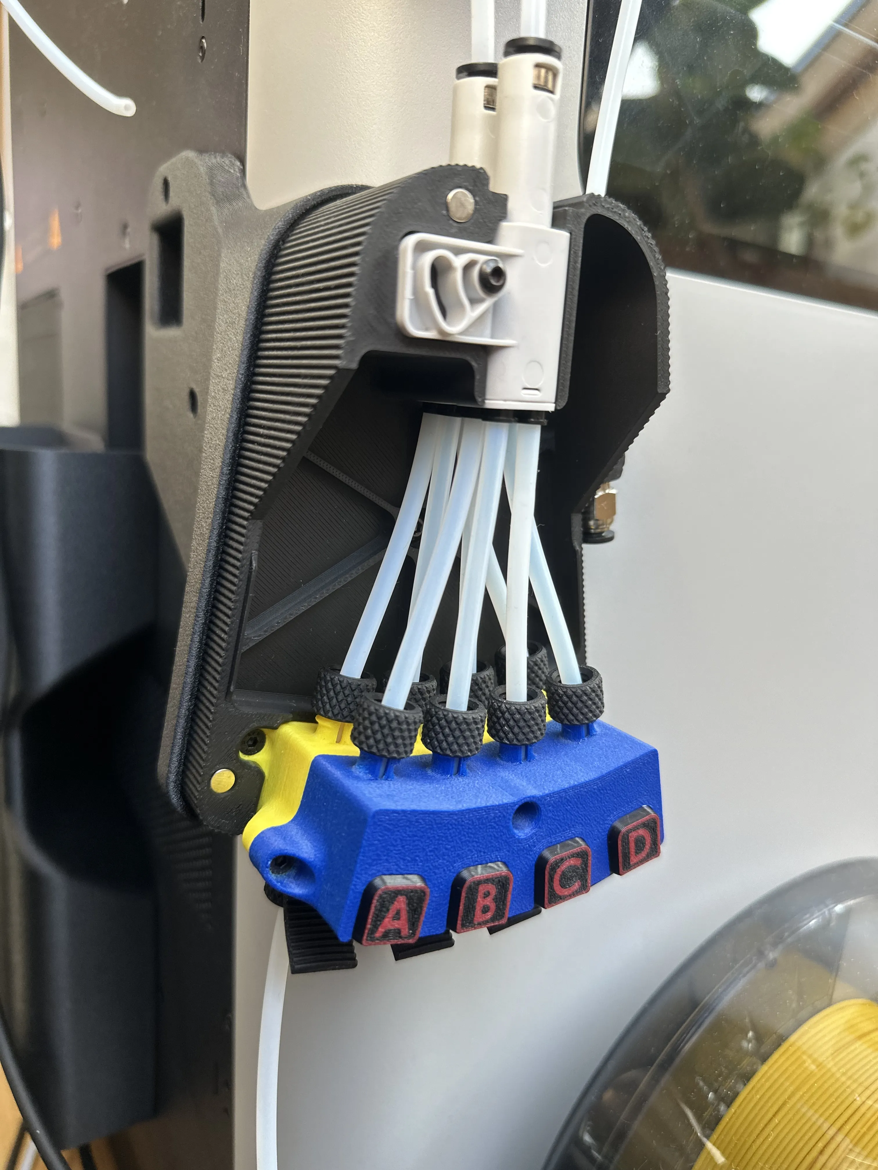
The tabs are aligned by the pockets. Otherwise they would have the tendancy to slide upwards, because the magnets in them are not fully concentric with the ones in the top half of the hub.
Attach the magnetic cover(s) and connect your AMS, just like you did it with the internal tubes!
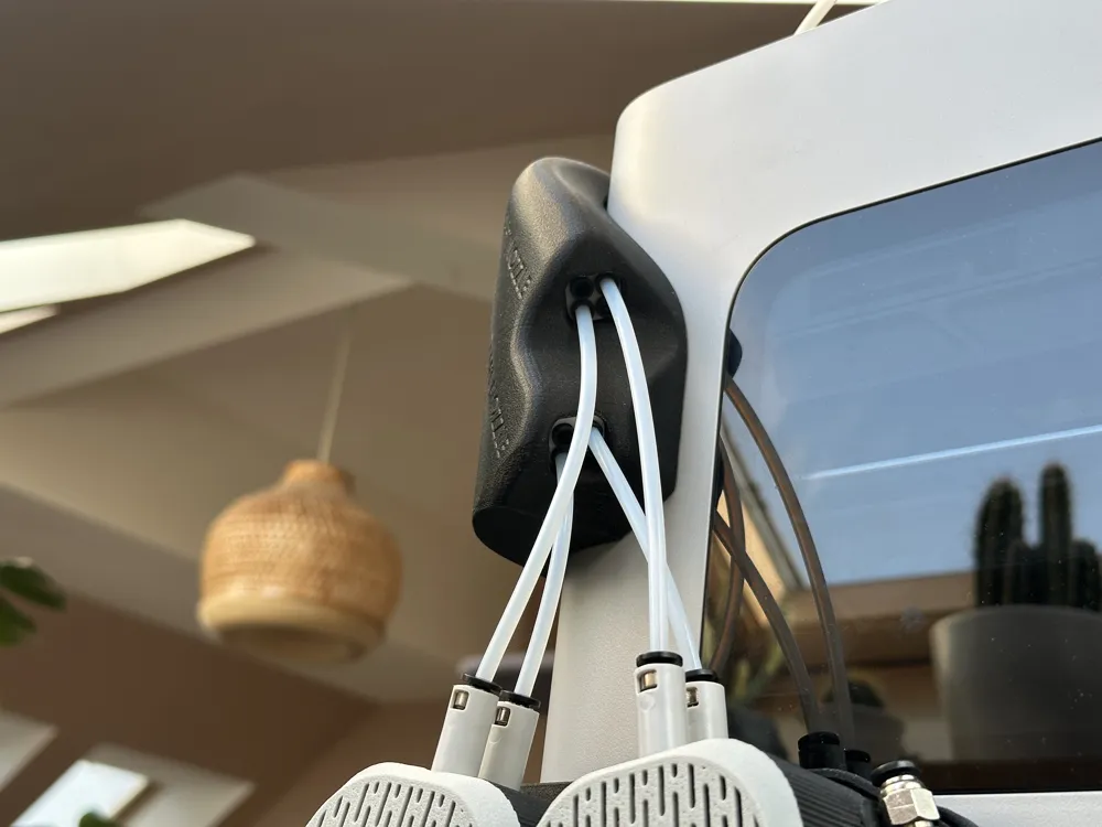
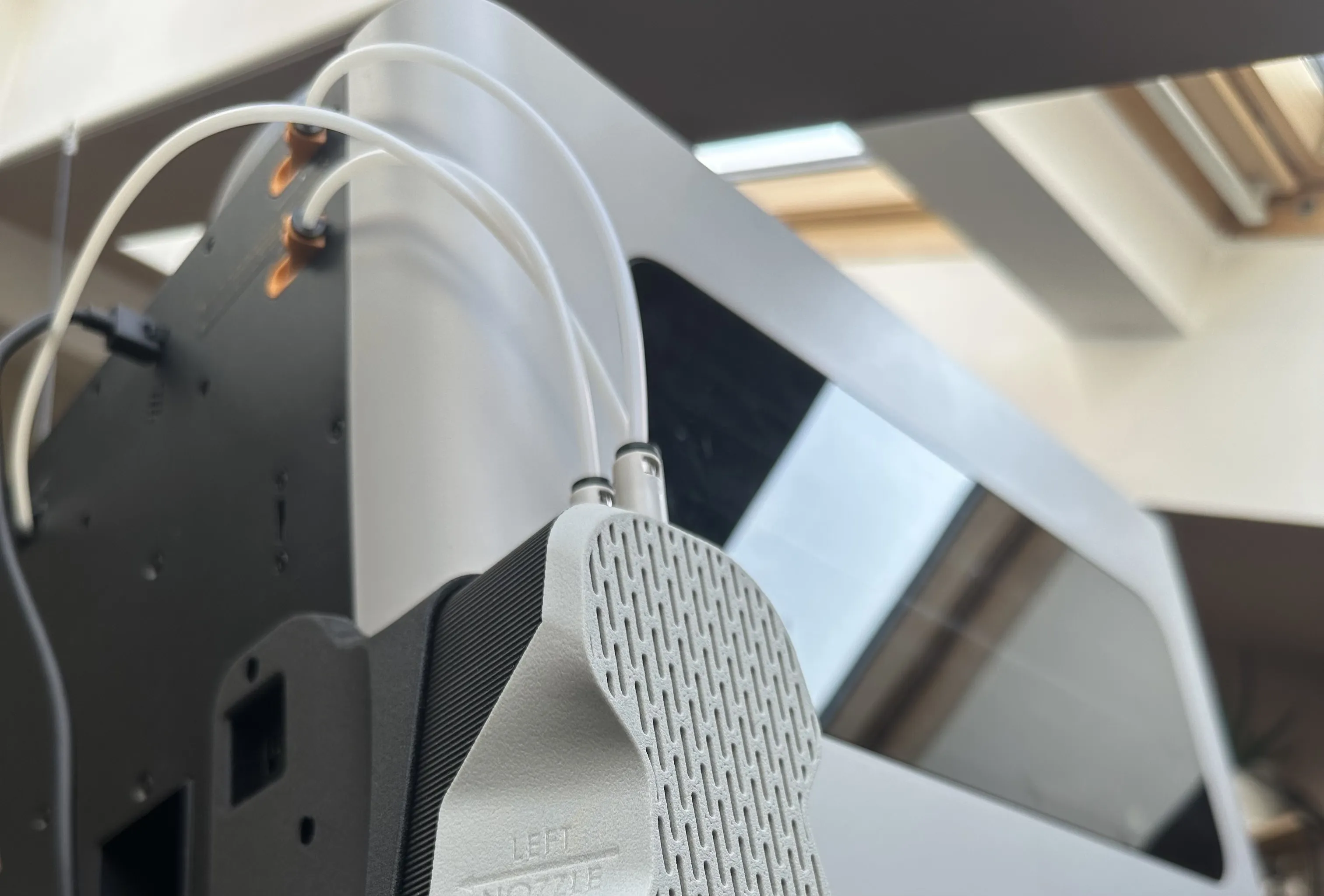
if you build the version for 4 AMS you can connect the outputs of your single module hdirectly to the printers inputs!
When you install the tubes for external material, make sure the endings of both Tubes are fully pushed THROUGH the fittings and touch each other inside the channel - like this:
For the versions for 8 or 12 AMS, an additional pair of 4in1s is require, to bundle the outlets of the modules into one.
It‘s up to you if you want to use the adapters like this:
or print my input terminal and have it look a little bit cl1eaner (well at least in my opinion 😃):
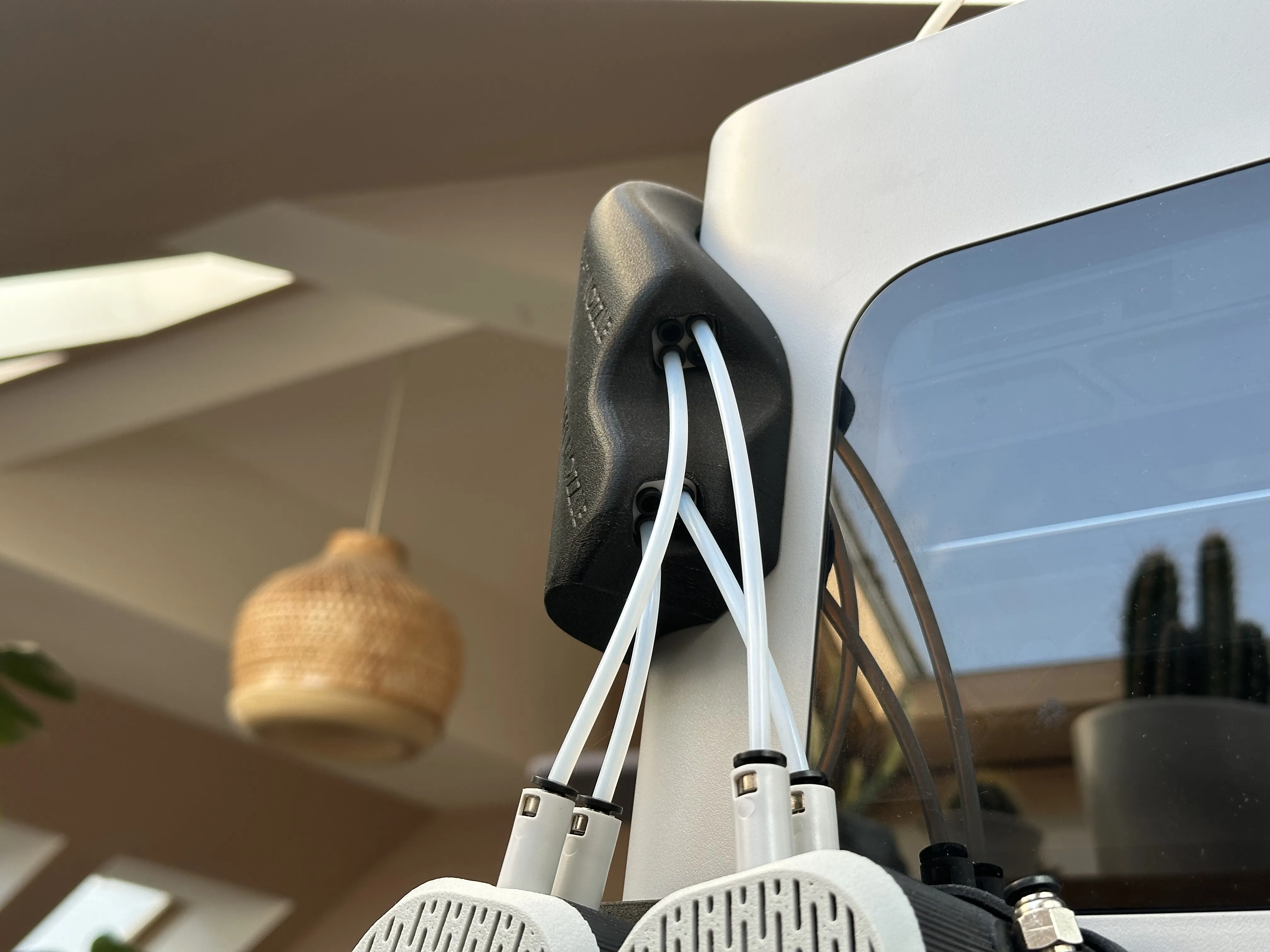
The model is assembled and attached as follows:
slide the two adapters in the pockets on the inside of the input terminal cover and fix them with two M3x12mm countersunk screws:
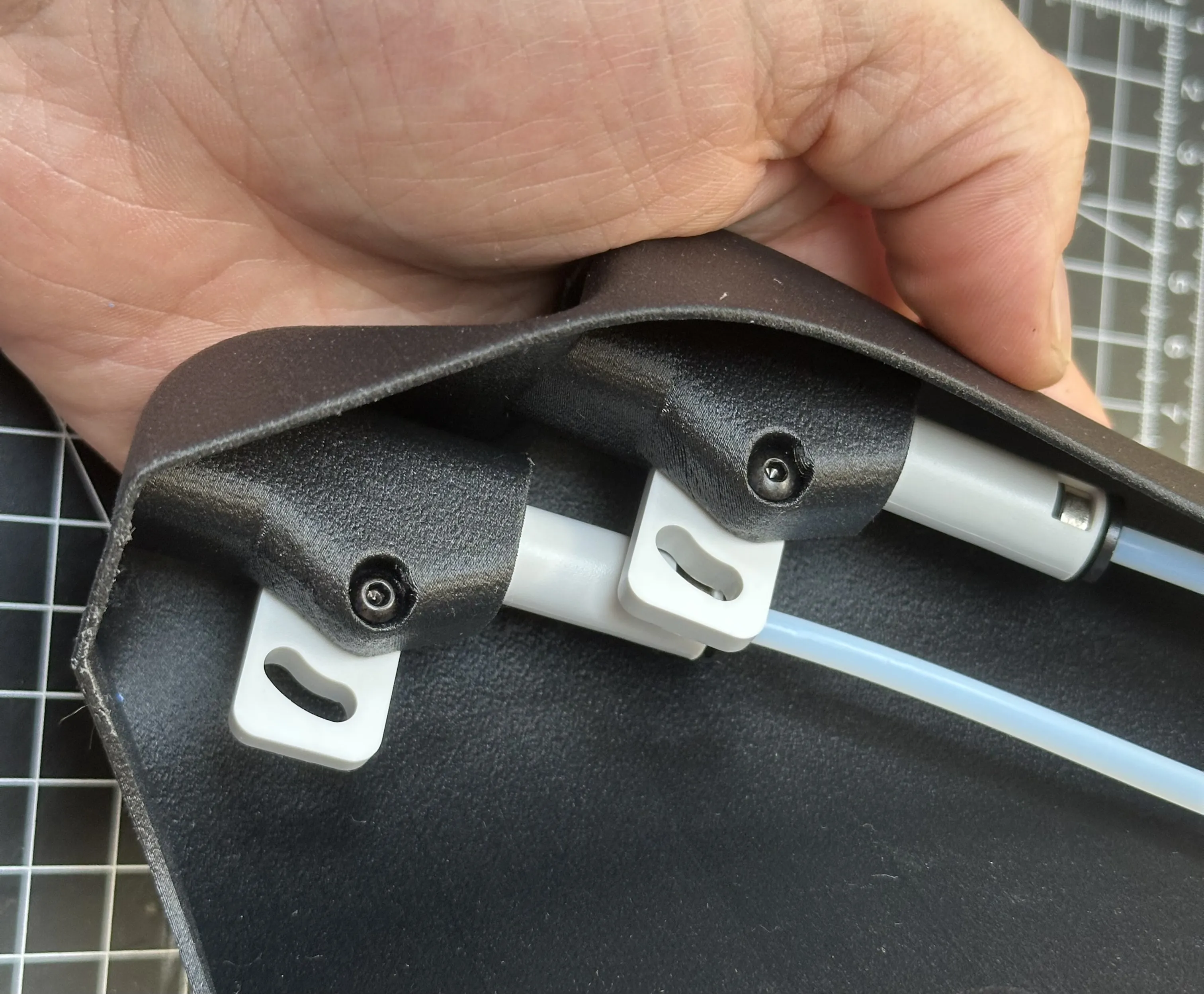
to me it was easier to attach the tubes to the adapters first. But it can be done the other way around too.
The top tube (right nozzle) needs to be 170mm long
The bottom tube (left nozzle) needs to be 178mm long
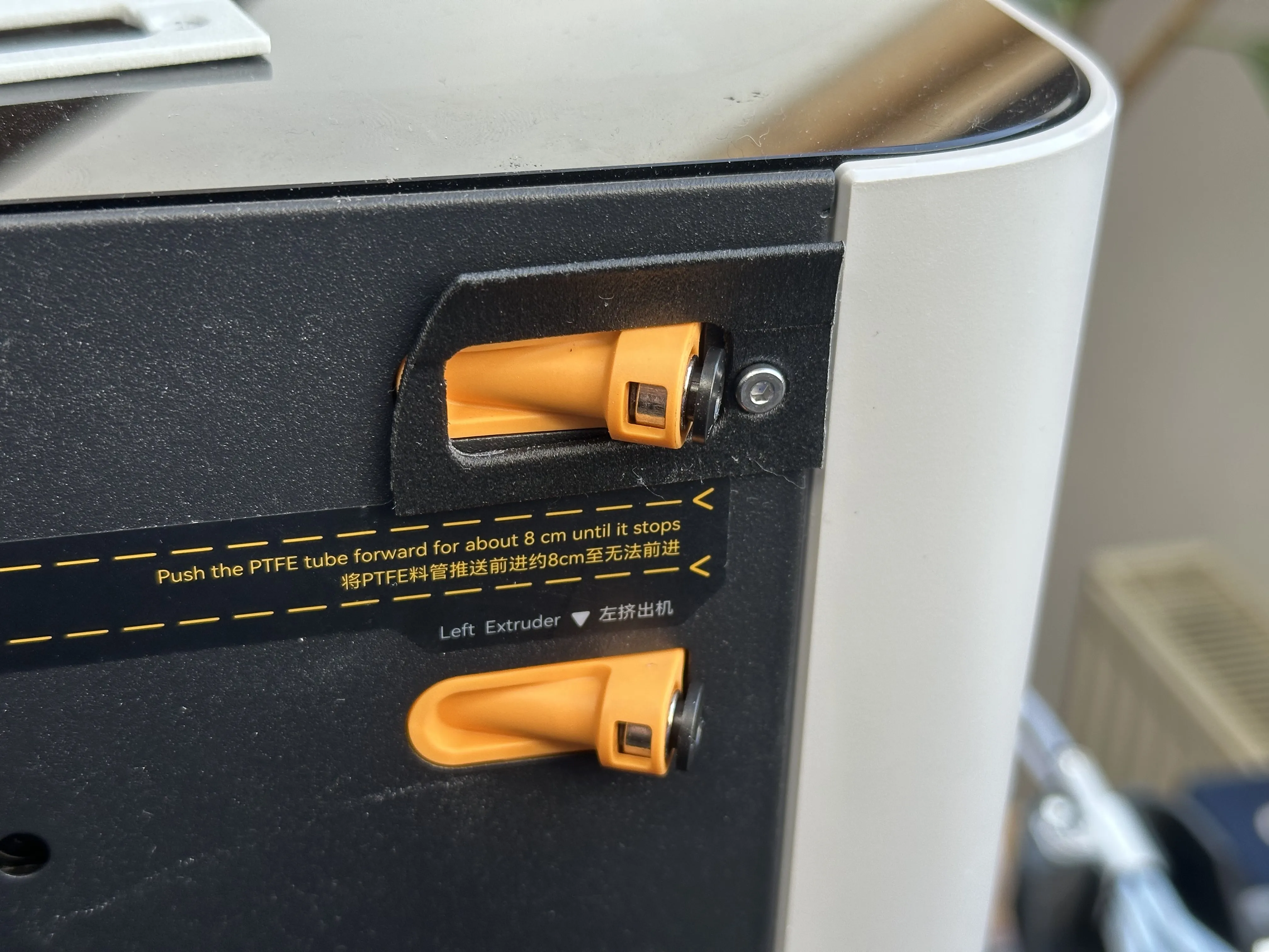
Install this holder with the shortened 3mm selfcutting screw (see hardware list, 8mm long):
Attach the tubes like this, then fully press them in! (Can be a little bit fiddly when you have big hands):
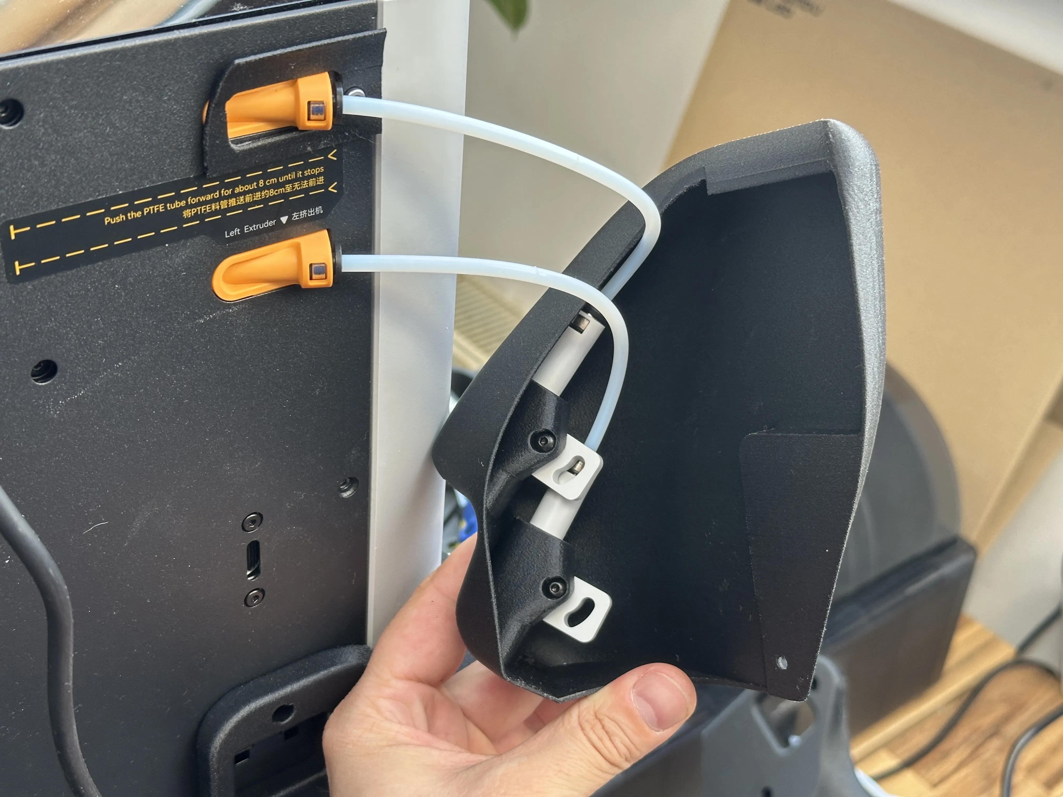
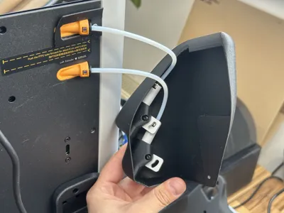
Then attach the cover to the printer.
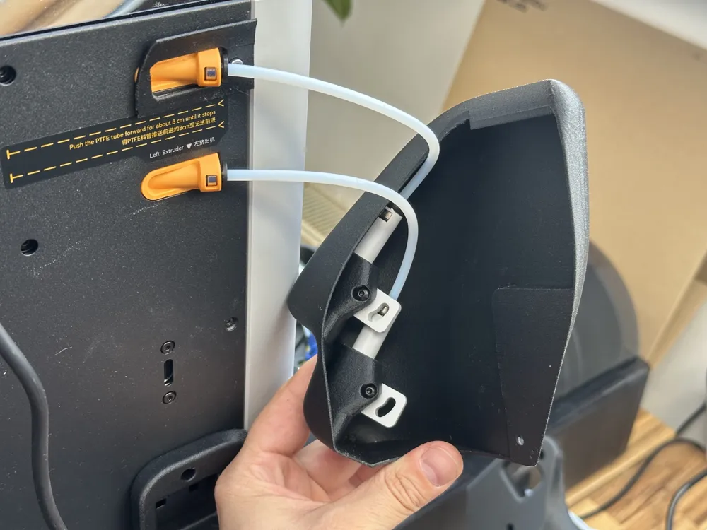
Hang it on the holder from above an align the hole in the bottom section with one of the rear panel mounting points (of course, the stock screw needs to be me removed first)

secure it with one M3x8mm countersunk screw.
The only thing left to do now, is to get the tubing done! Make sure left goes to left, and right to right paths!
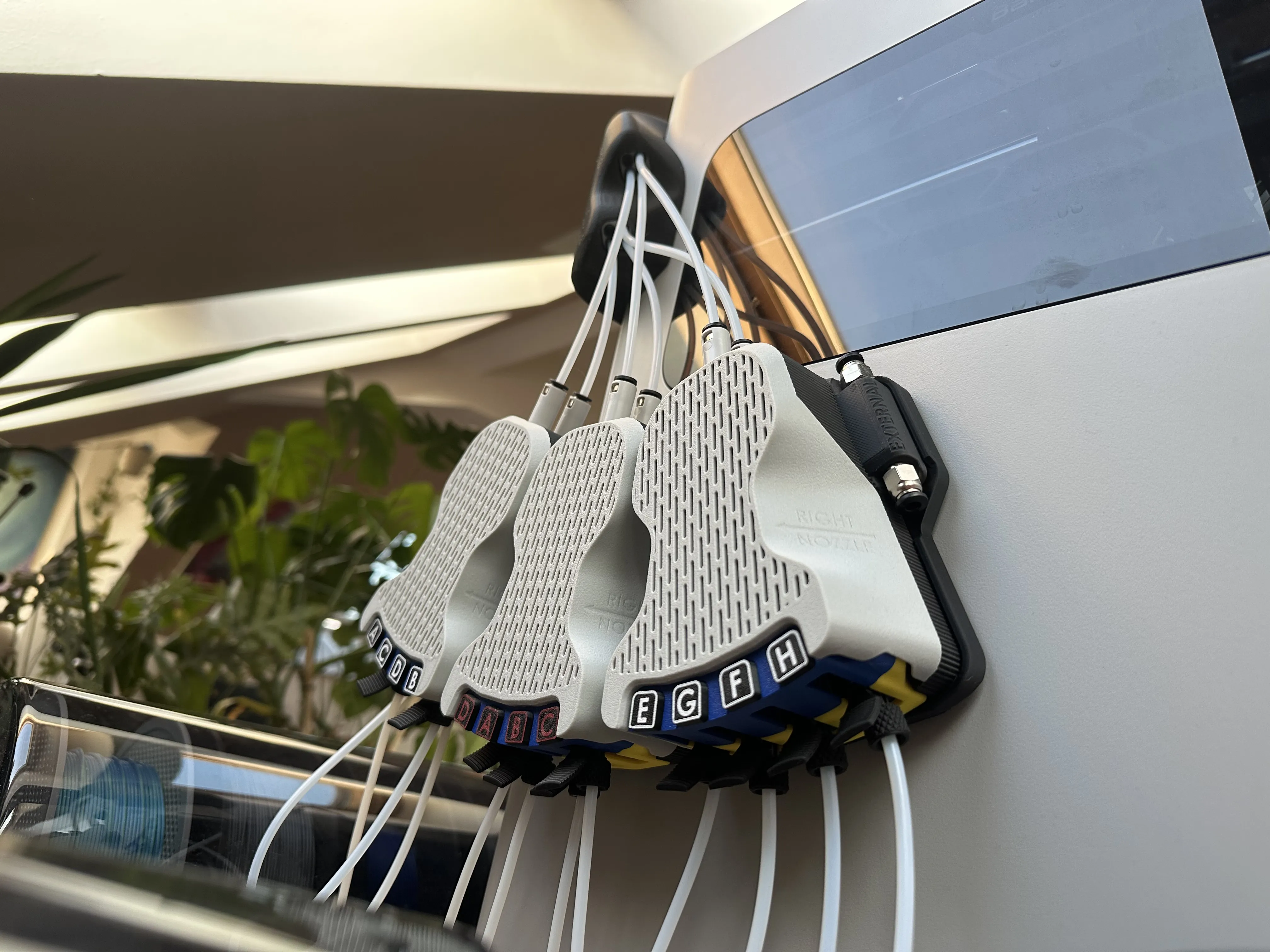
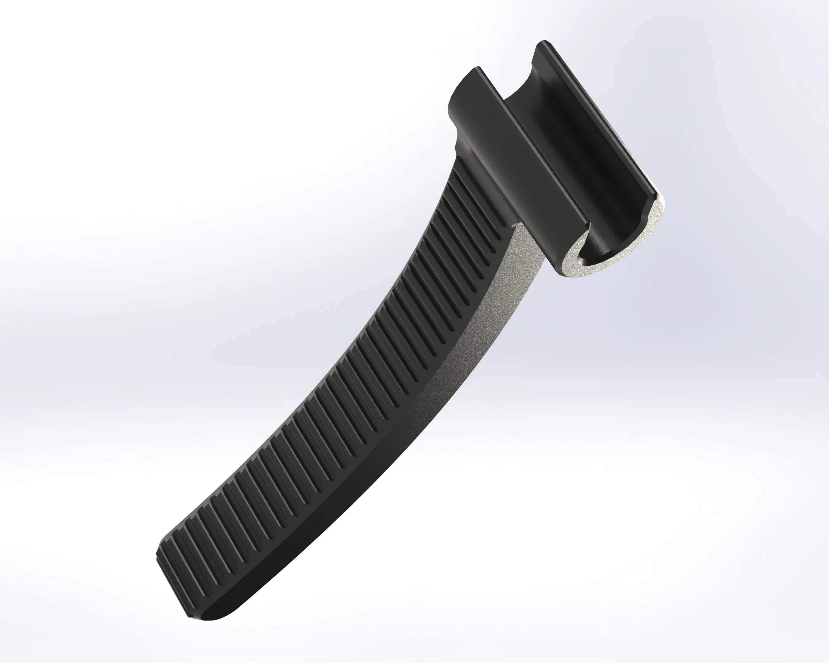
Disconnecting the tubes from the adapters in the input terminal can be a little bit challenging, so i added this little tool to make it easier! (found on this page as a separate print profile!)
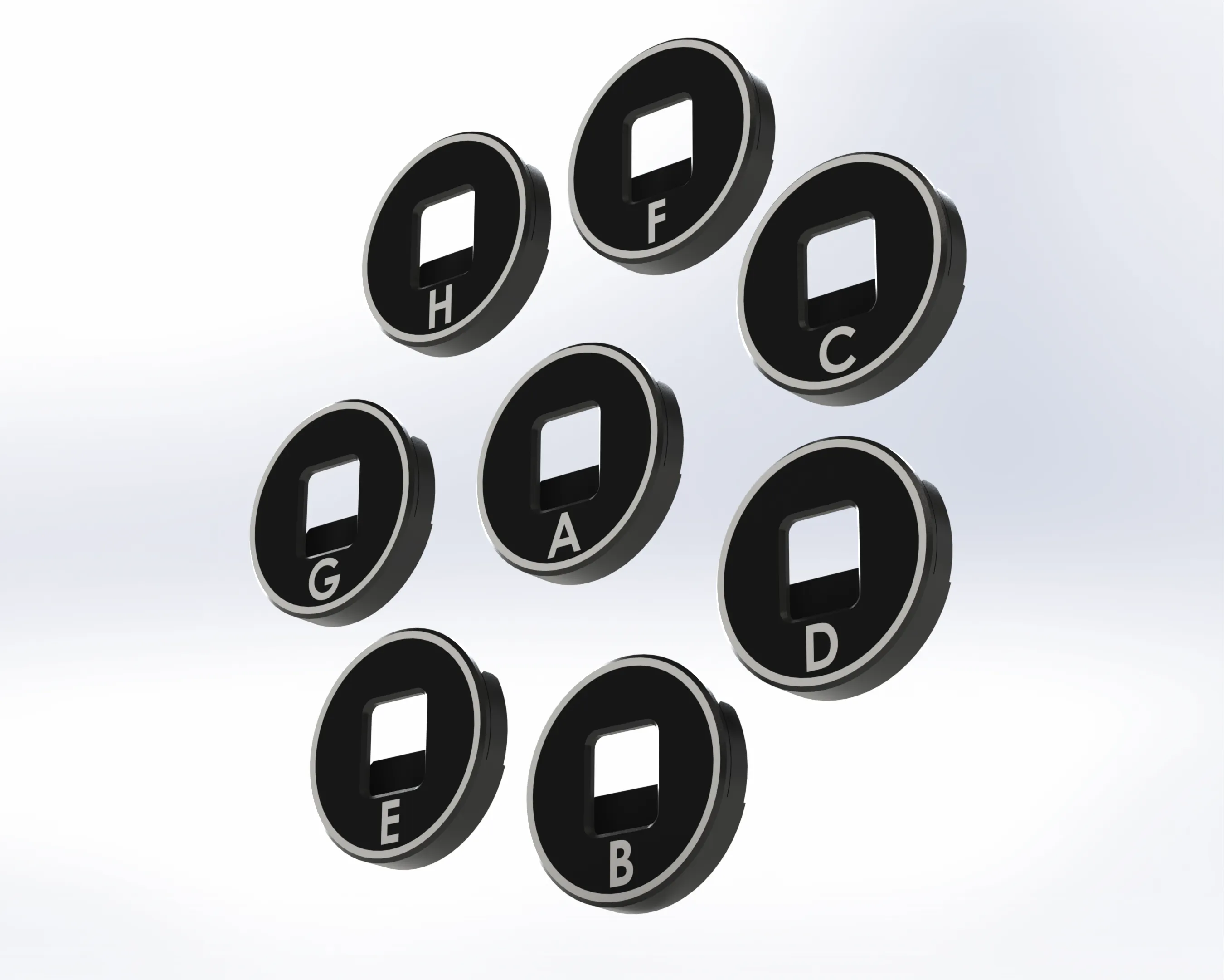
I also added a plate for these AMS Labels, that snap on the little circular handle. It can be a little confusing with so many units.
With these markers, you always know which unit is which!
If you don't need all of them, just remove the unwanted ones before starting the print (thats even possible through bambu handy!
*****If you made it here, congratulations, you finished the project!*****
I can‘t believe i’ve completed this one. This is by far my most time consuming project yet.
I hope you guys like it a lot!
You'll hear from me soon :)
M.I.M
License

You shall not share, sub-license, sell, rent, host, transfer, or distribute in any way the digital or 3D printed versions of this object, nor any other derivative work of this object in its digital or physical format (including - but not limited to - remixes of this object, and hosting on other digital platforms). The objects may not be used without permission in any way whatsoever in which you charge money, or collect fees.


Comment & Rating (789)