MT3608 Micro USB Boost regulator panel mount


Print Profile(1)

Description
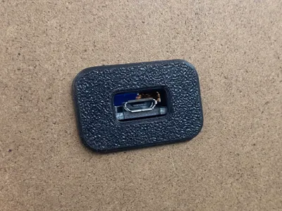
When you need to power your creation from USB 5V but it needs 12V or another voltage higher than 5, you usually resort to using the common MT3608 boost converter. This is usually bought in the form of an assembled PCB and can be bought with a USB connector. To mount that to your night light or backlit sign is a problem, either the USB lead has to go into the enclosure or you have to mount it to expose the USB connection so that you can plug a USB power cable into it.
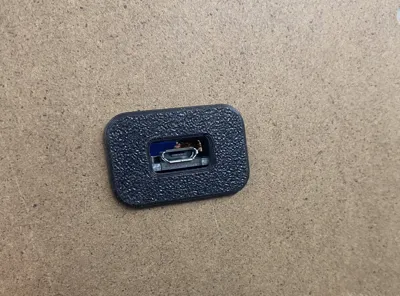
This model allows you to neatly mount the board in the back (or front) panel exposing the USB connector ready for your cable.
The panel can be up to almost 4mm thick if you use the nut to hold it against the panel.
Preparation
- A rectangular hole, 25mm x 13.5mm is needed in the panel
- Clean out the pin holes in the carrier and bezel, assemble them when you do this. Use a 5/64th or 1.8mm bit. A 1.5mm bit will also work if you work it around a bit. 2mm is OK but you may need to glue the filament into place if its too loose
- A short piece (less than 10mm) of filament can be used to pin the board carrier to the bezel.
- If you want to use glue, for PLA or PETG use PVC to ABS "Transition Cement” or CA glue
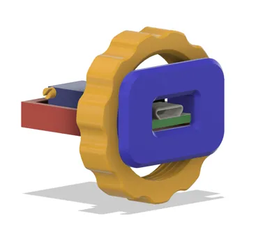
Assembly is straightforward,
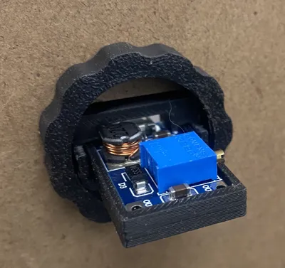
- insert the board into the carrier, be sure to have the output wires soldered on already.
- Glue the carrier into the bezel or use 3 short pieces of filament in the holes to pin the carrier to the bezel
- Trim the filament pins flush with the bezel so that it fits into the rectangular hole in the panel
- Insert the bezel and carrier into the panel and glue or add the nut to keep it in place. The nut has a flat side to go against the panel. The side of the nut that was on the buildplate has a chamfer and may be difficult to thread onto the bezel because of the slight distortion of that surface when it was printed.
WARNING
My board is 30mm x 17mm (see picture), has square corners. Yours may be different.
Comment & Rating (1)