
AC 1 phase motor NO steel core
Print Profile(1)

Description
Video of it running: ( https://www.youtube.com/shorts/OVKwz10mPEQ )
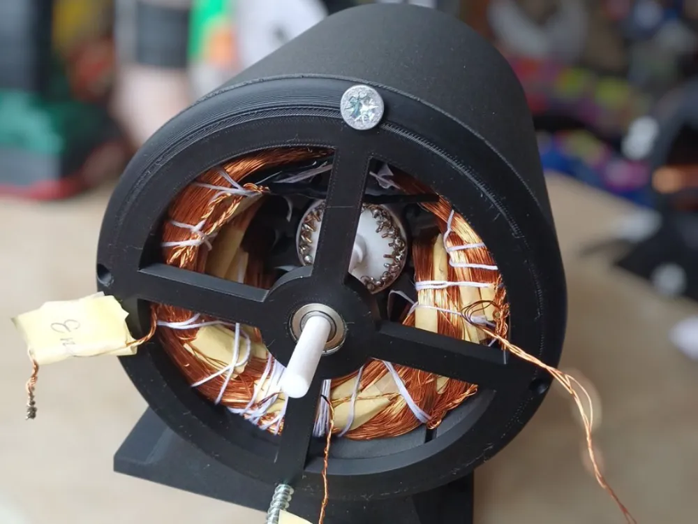
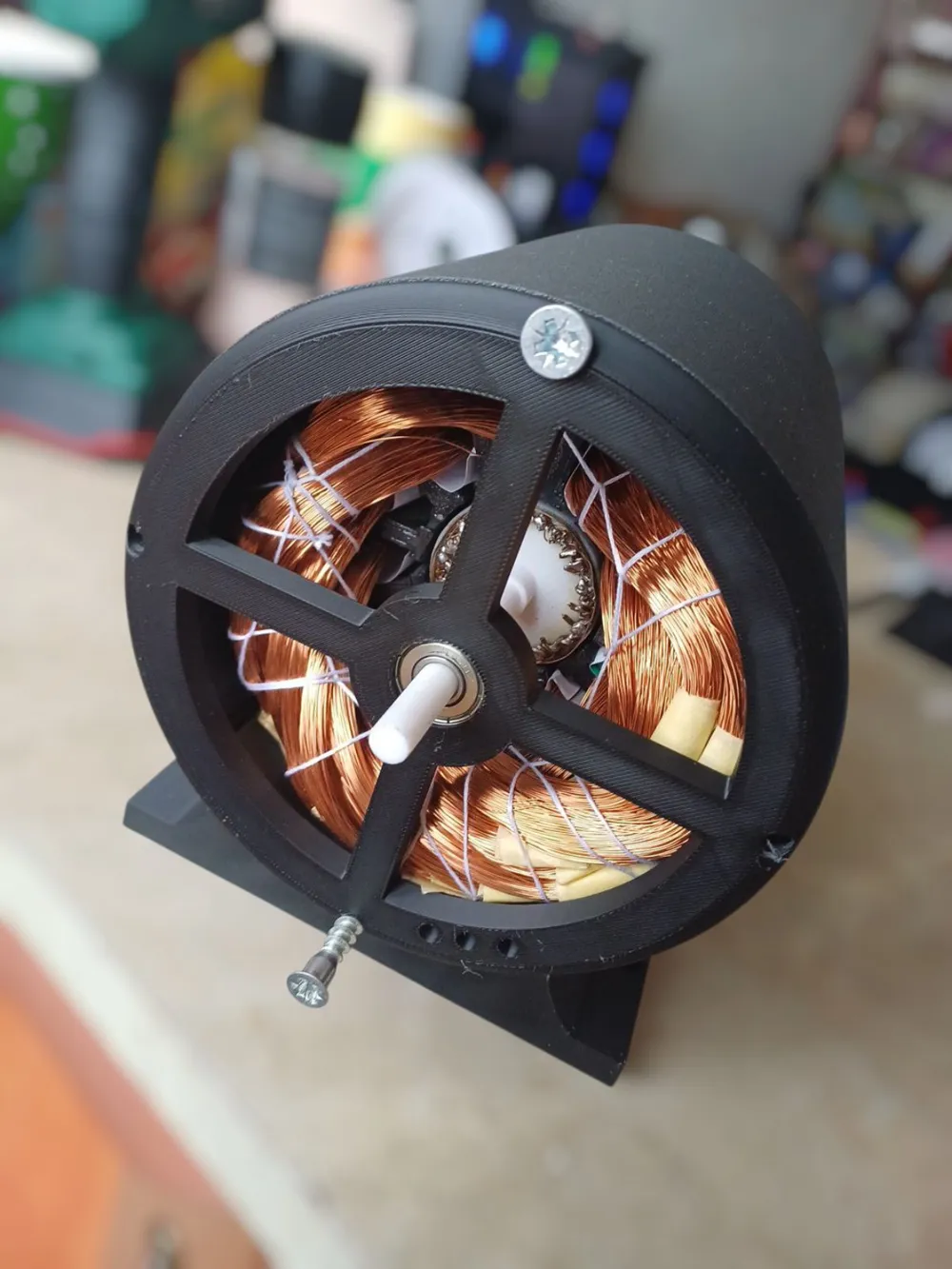
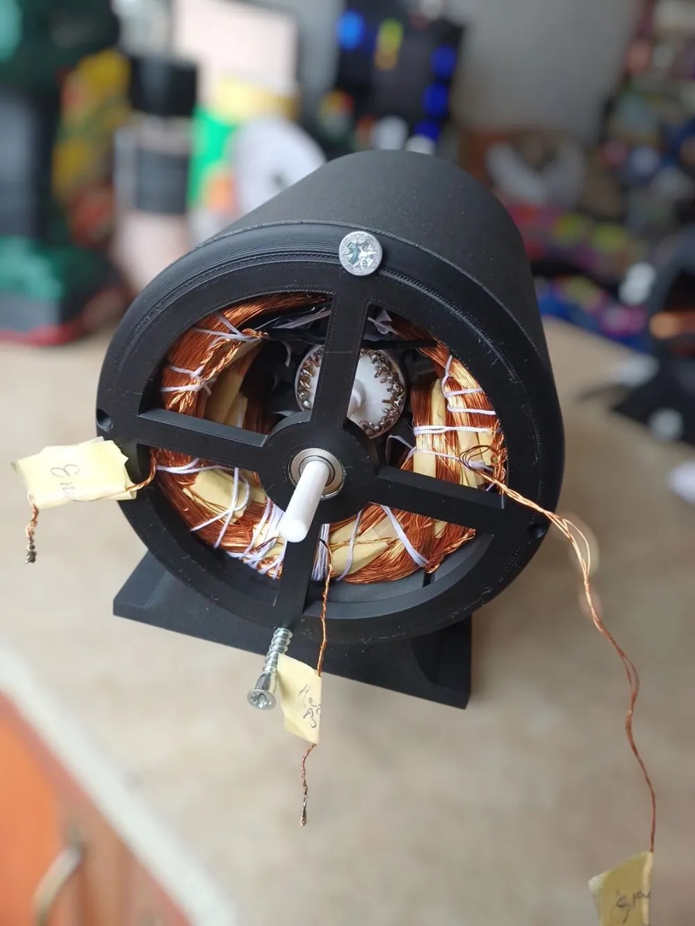
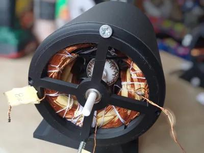
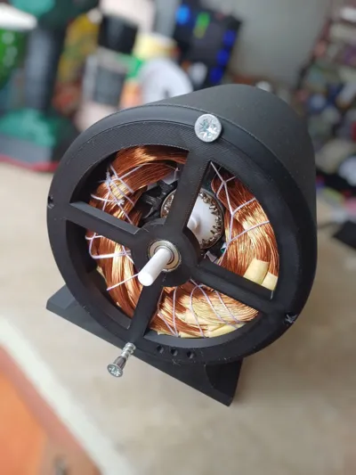
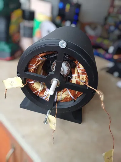
Asynchronous Motor Made Entirely from Plastic
The stator uses Iron dust, after you put it into the stator, you will need to glue the top part of the stator with glue that can be spread and pushed into crevasses of the stator with fingers, so that no iron dust will leak out. The glue I used is: poxipol transparente, but you can use any other glue that covers those characteristics.
Warning: This project is very difficult to make, requires a lot of winding, and is not efficient. It can only be used as a demonstration piece or to test your skills in winding electric motors—or to impress your teachers—but it is not particularly useful for any practical application.
The stator and motor housing must be made from high-temperature-resistant plastic. The stator especially should be made of a plastic that can withstand at least 130–150 degrees Celsius. The housing can be made from ABS.
The rotor uses 1.5 mm² copper rods inserted and short-circuited with thinner copper wire, then soldered together. There are 23 rods. I made the rotor out of PLA, but ABS or at least PETG is recommended.
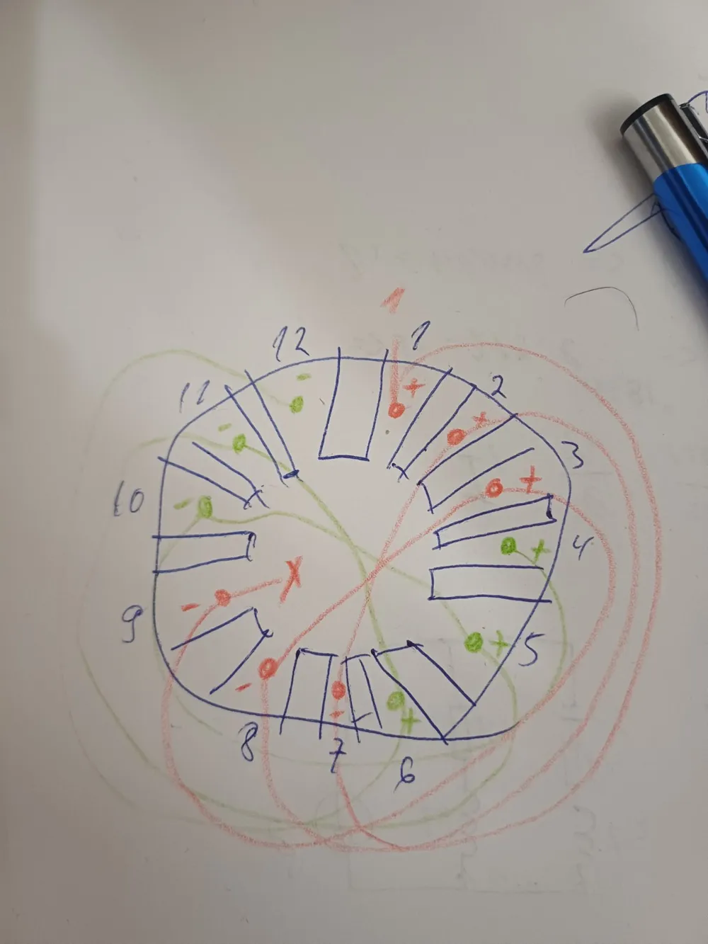
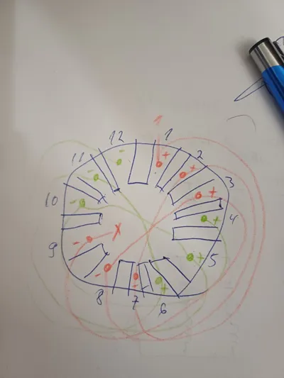
As for the windings, I made 110 turns per coil using 0.35 mm² copper wire. Each slot holds 4 such coils of 110 turns each, connected in parallel to reduce the wire resistance. You can use thicker wire, but it becomes very difficult to fit it into the slot.
My configuration yields the following parameters:
- Inductance per phase: 20 mH
- Resistance per phase: 8 Ω
One of the phases is phase-shifted with a 210 μF bipolar capacitor, rated at 50 V (I blew up a few; you need at least 100 V).
Again, I must stress: This project is extremely difficult, expensive, and time-consuming.
I’m publishing it as a file on MakerWorld in case someone is interested in giving it a try.
The entire project cost me around 150–200 euros, including wire, capacitors, bearings, filaments (plastics), etc.
+ You’ll need an autotransformer unless you plan to add a lot of turns to be able to use mains voltage (which is very dangerous—do not attempt this!).
Oh, and the bearings for the rotor are 608ZZ.
License

You shall not share, sub-license, sell, rent, host, transfer, or distribute in any way the digital or 3D printed versions of this object, nor any other derivative work of this object in its digital or physical format (including - but not limited to - remixes of this object, and hosting on other digital platforms). The objects may not be used without permission in any way whatsoever in which you charge money, or collect fees.


Comment & Rating (5)