CinePi Frame8 - Raspberry Pi Box Camera V1


Print Profile(1)
Description
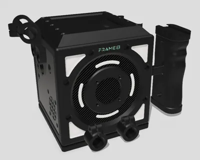
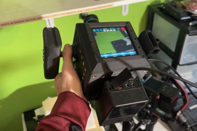
🎥 CinePi Frame8 – An Open-Source Cinema Camera You Can Make at Home
The CinePi Frame8 is a compact, 3D-printable DIY cinema camera powered by the open-source CinePi V2 firmware. Built around the Raspberry Pi 4 Model B and HQ Camera Module, it brings true RAW video capture into a maker-friendly package that's easy to print and assemble.
Designed with beginners in mind, the entire build takes about an hour after printing.
⚠️ NOTE: Always power off the device using the touchscreen interface, not the physical power button. Once the system is shut down, then remove USB-C power. Improper shutdown via the physical button may damage the camera.
🔧 Key Features:
- Powered by CinePi V2 Firmware (Open Source)
- Sony IMX477 12.3 megapixel super8 sensor
- Records in CinemaDNG RAW format
- External recording via USB 3.0 SSD (Samsung T7 recommended)
- Touchscreen controls for ISO, shutter speed, frame rate, white balance, etc…
- Designed for reliable, continuous recording with active cooling and proper power management
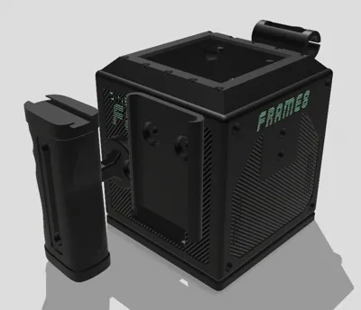
- Custom 3D-Printed Enclosure
- Compact and modular
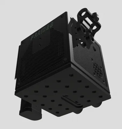
- Built-in 1/4"-20 mounting points for accessories and tripods
- Designed to be printed on Bambu Lab printers (fully tested)
- Beginner Friendly
- No soldering required
- Straightforward wiring with FPC and JST connections
- Included AMS and NON-AMS camera body plates
- Included slicer profiles provided
Current Accessories:
Enhance your rig’s usability and expandability with these essential modular components:
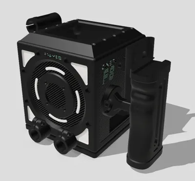
- Handle Mount
A secure bracket for attaching side or top handles, providing stability and flexible mounting options. - Side Handle
Ergonomically designed for handheld shooting, this side-mounted handle offers improved balance and control during movement. - External SSD Holder
A compact mount designed to hold and secure external SSDs, ensuring uninterrupted high-speed recording. - 15mm Bar Holder
Attaches seamlessly to your rig to support standard 15mm rods—ideal for accessories like follow focus systems and lens supports. - 15mm Bar Cheese Plate
A versatile mounting plate with multiple threaded holes (1/4"-20), compatible with 15mm rods for expanded rig customization.
⚠️ Limitations:
- Audio capture not included.
- Single physical power button. All controls are done via the Pimoroni HyperPixel 4.0 square touch display.
- This is a DIY enthusiast camera, not intended as a drop-in replacement for professional cinema cameras.
To build this project you need:
- Raspberry Pi 4 Model B: https://www.amazon.com/dp/B0899VXM8F?ref=ppx_yo2ov_dt_b_fed_asin_title]
- Raspberry Pi HQ Camera Module: https://www.adafruit.com/product/4561
- 16mm Telephoto Lens: https://www.adafruit.com/product/4562
- Pimoroni HyperPixel 4.0 Square - Touch Display: https://www.microcenter.com/product/631631/HyperPixel_40_Square_-_Touch_Display_for_Raspberry_Pi;_Capacitive_Touch_-_PIM470_-_High-speed_DPI_interface;_60_FPS_frame_rate;_40"_IPS_(wide_viewing_?gQT=2
- 40-pin FPC to Straight 2x20 IDC Female Socket Header: https://www.adafruit.com/product/4905
- 40-pin FPC to Straight 2x20 IDC Male Plug Header: https://www.adafruit.com/product/4904
- 40-pin 0.5mm pitch FPC Flex Cable with A-B Connections - 25cm long: https://www.adafruit.com/product/4933
- 90 Degree USB-C Cable: https://www.amazon.com/dp/B08HPVP1GY?ref=ppx_yo2ov_dt_b_fed_asin_title
- 22mm Threaded USB-C Mount: https://www.amazon.com/dp/B0CZPP24YQ?ref=ppx_yo2ov_dt_b_fed_asin_title
- JST-PH Wire: https://www.amazon.com/dp/B0D9R2DYL1?ref=ppx_yo2ov_dt_b_fed_asin_title
- 40 Pin Header (shorter pin variant): https://www.amazon.com/dp/B08GC18NMK?ref=ppx_yo2ov_dt_b_fed_asin_title
- 1/4"-20 Slotted Screws (Buy 4 of these): https://www.amazon.com/dp/B07PB99Y5B?ref=ppx_yo2ov_dt_b_fed_asin_title
- 1/4"-20 Heat Inserts (Recommended to buy 2 packs): https://www.amazon.com/dp/B07PB99Y5B?ref=ppx_yo2ov_dt_b_fed_asin_title
- M2.5 Heat Inserts: https://www.amazon.com/dp/B0CS6YVJYD?ref=ppx_yo2ov_dt_b_fed_asin_title
- M2.5 Standoffs: https://www.amazon.com/dp/B0CS6YVJYD?ref=ppx_yo2ov_dt_b_fed_asin_title
- M2.5 Hex Screws: https://www.amazon.com/dp/B0CXQ4QTGT?ref=ppx_yo2ov_dt_b_fed_asin_title
- Geekworm X735 Power Management Board: https://www.amazon.com/dp/B07R45W1LN?ref=ppx_yo2ov_dt_b_fed_asin_title
- Dupont Wires: https://www.amazon.com/dp/B07R45W1LN?ref=ppx_yo2ov_dt_b_fed_asin_title
- 12mm LED Momentary Switch: https://www.amazon.com/dp/B0C38PWG2B?ref=ppx_yo2ov_dt_b_fed_asin_title
- Noctua NF-A4x10 5V PMW Fan: https://www.amazon.com/dp/B07DXS86G7?ref=ppx_yo2ov_dt_b_fed_asin_title
- Heat Shrink Tubing: https://www.amazon.com/Wirefy-180-Heat-Shrink-Tubing/dp/B084GDLSCK/ref=sr_1_9
- Samsung T7 Portable SSD 1TB: https://www.amazon.com/gp/product/B0874XN4D8/ref=ox_sc_act_title_3?smid=ATVPDKIKX0DER&psc=1
- 1/4"-20 x 3/4" Button Head Socket Cap Bolts: https://www.amazon.com/gp/product/B07TJN6L2J/ref=ewc_pr_img_1?smid=A23DCXE387KYKE&psc=1
- SmallRig Mini V-Lock Assembly Kit: https://www.amazon.com/SmallRig-Assembly-Battery-Release-Threaded/dp/B08TC117PL/ref=sr_1_16
- SmallRig V-Mount Battery: https://www.amazon.com/SmallRig-Battery-VB99-Camcorder-Filmmaker/dp/B0B6Z9K42P/ref=sr_1_3_pp
Hardware Specifications:
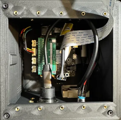
Utilize the provided Geekworm 40pin spacer that comes with the Geekworm power management board between the Pimoroni HyperPixel 4.0 Touch Display and the FPC board. This spacer will ensure proper connection between the Display and the FPC board carrying signal back to the Raspberry Pi 4 Model B.
4 5mm Standoffs for mounting the Raspberry Pi 4 Model B to the interior of the camera body. Thread 4 M2.5 heat inserts onto the standoff first, then heat sink the standoffs and heat inserts together into the interior of the camera body to ensure a level mounting surface for the Raspberry Pi 4 Model B.
4 20mm Standoffs for mounting the Geekworm power management board on top of the Raspberry Pi 4 Model B. When attaching the Geekworm power management board to the Raspberry Pi 4 Model B use a 40 pin spacer. this will make sure you don't bend your camera cable, and that your pins have a solid connection between the Raspberry Pi 4 Model B and Geekworm power management board.
22 total M2.5 Heat inserts. 4 sunk into the camera body to attach the lid. 4 sunk into the front of the camera body to attach the sensor. 10 sunk into the lid to attach the display fasteners and frame, and the previous 4 mentioned for mounting the Raspberry Pi 4 Model B on the interior of the camera body.
35 1/4"-20 Heat Inserts (Not including cheese plate accessory). These are for mounting various attachments to the outside of the camera body.
Connect the FPC boards to each end of the flex cable, then attach one board to the Raspberry Pi 4 Model B and the other to the Pimoroni HyperPixel 4.0 Square touch Display.
Replace the Geekworm power management board PMW fan with the Noctua PMW fan. This will require snipping the JST-PH connector off of the Geekworm fan or using one you have ordered. Once you have a JST-PH 4 pin connector, strip the ends of the protruding wire exposing 4 leads. Cut a male Dupont wire in half and strip the cut ends. Thread some heat shrink tubing over the Dupont wire, then twist the corresponding exposed leads from the JST-PH wire to the Dupont Wire. I will attach diagrams for the correct connections below. You will do a similar process with the power button when attaching it to the Geekworm power management board.
- On Board PMW Fan Layout (Diagram to the right): https://pbs-prod.linustechtips.com/monthly_2022_12/image.png.eaac089dbd179246ec9841eaa21a8e54.png
- Noctua Fan Wire Layout: https://noctua.at/media/wysiwyg/faqs/noctua_pin_configuration_5v_fans.png
4 4mm M2.5 hex screws to secure the Geekworm power management board to the 20mm standoffs protruding from the Raspberry Pi 4 Model B.
4 12mm or larger M2.5 hex screws to secure the camera sensor to the exterior of the camera body.
4 6mm or 8mm M2.5 hex screws to secure the camera body lid to the camera body.
10 12mm M2.5 hex screws to secure the display frame and fasteners to the camera body. 12mm hex screws ensure your inserts do not strip. Longer hex screws will cause issues when mounting.
Mount a SmallRig Mini V-Lock Assembly to the back of the camera, then attach the SmallRig V-Mount Battery. Use only the USB-C output to power the device.
⚠️ Do NOT use other outputs – they can damage the board!
Make It Your Own
Take your rig even further—design custom accessories, create a cage, or modify components to fit your exact workflow. With the original Shapr3D CAD file included, you have full access to the base model, making it easy to prototype, iterate, and build entirely new parts. Whether you're optimizing for function, weight, or style, the rig is your canvas.
Download the source file and start creating. Your build, your way.
📦 Final Note:
A full build guide (with visuals) is coming soon.
If anything is unclear, feel free to comment or reach out for clarification.
Other Helpful Videos:
Comment & Rating (4)