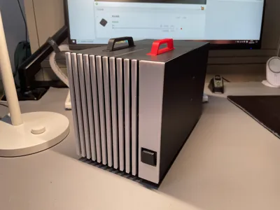
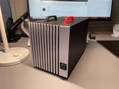
847 Case Dual-Heatpipe Cooler A1 mini printable


Print Profile(1)

Description
Print using Bambu PLA+
Parts List:
M2x6 screws x19 Fan screws x4 Hard drive screws x4
120mm fan dust filter x1 Fan dust filter from Tieq
120mm fan x1 I used the Thermalright TL-T12B
Dual-copper tube heatsink x1 I used a generic brand (RUIX X2000, about 15 yuan)
Hard drive power and data cable x1
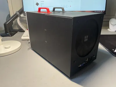
847 power cable x1 I used a custom-made cable
Fan speed control cable x1 The 847 BIOS lacks smart fan functionality, necessitating this addition
Hard drive (optional) 500GB 2.5-inch HDD, 128GB mSATA SSD
Apologies, I only have 2.5-inch mechanical drives on hand, thus currently only the 2.5-inch tray and bracket are included I believe the design accommodates a 3.5-inch drive (may require a portion to protrude)
(Optional) Mechanical keyboard key switches and keycaps, low-profile switches recommended, switch soldering and jumper wires required, keycaps can use these round keycaps from nimrodbdd

Regarding the custom power cable: these are the connector dimensions; they should fit the rear panel; additional adhesive is recommended for secure mounting

Assembly Instructions:
Clean the print bed with soap before printing, allow to cool before removal, carefully remove supports afterwards, connector section bridging is recommended to reduce print speed (nozzle may collide with side structures, leading to root breakage)
Before assembly, try screwing the screws into the holes first for easier subsequent assembly
Step 1: Remove the heatsink fan, install the heatsink, connect the 12cm fan, speed control cable and power cable, align the motherboard connector with the panel and install, tighten the screws but do not overtighten


Step 2: Secure the two small connectors using screws (the image shows them inverted for clarity, the order of steps 1 and 2 can be reversed, simply ensure correct installation)
Tighten the third motherboard screw and the other two, install the fan and dust filter (if installing an optional power switch, do so now)


Step 3: Insert the connector, tighten the screws (if the fan model deforms, causing a large gap, use a lighter to gently heat and readjust)


Step 4: Install the feet and attach the hard drive bracket panel and hard drive tray (tried using clips but they kept breaking, so I resorted to adhesive)


All Done!!!


I am still a novice modeler, please be understanding, remember to leave any modification suggestions in the comments section ^o^/
Comment & Rating (0)