
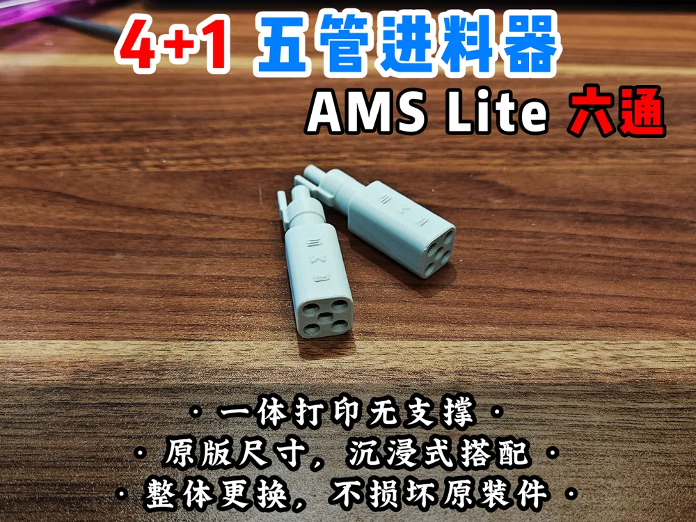
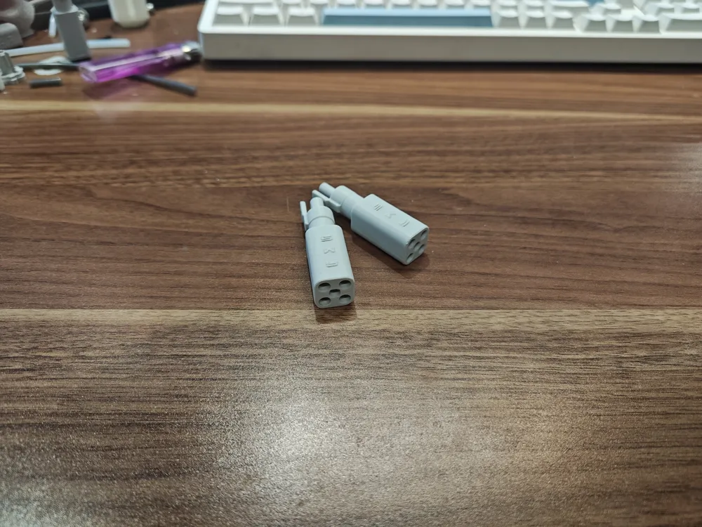
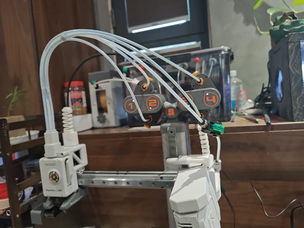
[Lao Teng] A-Series Six-Way Feed Inlet 4+1 Five-Tube Hub, Compatible with A1 and A1 mini
Print Profile(2)


Description
=============May 18 Optimization Notes===========
- Layer lines improved
- Companion protective sleeve: https://makerworld.com.cn/zh/models/1202409
=============April 3 Optimization Notes===========
Addressing the issue of the cable organizer model appearing disconnected in slicing software, this was due to the slicer's default setting of "Automatic Circular Shaft Hole Compensation". This is now disabled by default, and the model has been redesigned with increased thickness between the holes, enhancing its robustness. Disconnection will no longer occur regardless of the shaft hole compensation setting.
Addressing the issue of the six-port connector being too tight, I have increased the model's hole diameter by 0.15mm. However, due to variations in machines and materials, some users might still experience tightness. If this occurs, select "Quality - Automatic Circular Shaft Hole Compensation" in your slicer settings.
- Addressing the issue of filament feed difficulties experienced by some users, the layer height of the inner arc has been reduced in this iteration to create denser layers and minimize clogging.
=============Initial Release Notes===========
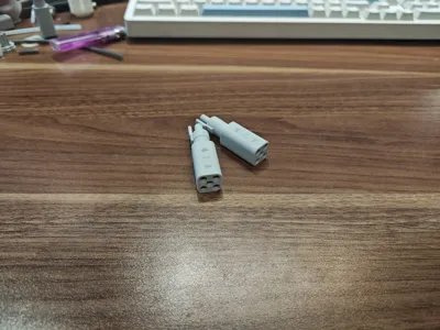
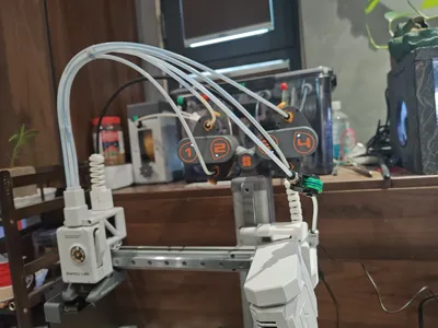
This is a six-port component that offers lossless replacement for the official five-port hub, matching the original's dimensions and aesthetics.
- Detailed installation steps are as follows:
Use a tool to remove the original five-port component


Remove the retaining ring from the original five-port component (rotate 90° to remove)

Install the retaining ring onto the newly printed six-port component. Ensure correct alignment of the locking mechanism.
Use a piece of old filament to clear the holes. If there is resistance, pull the filament back and forth several times to smooth any layer lines impeding the filament flow.

Apply lubricant. Apply to all areas below the retaining ring.


Install the six-port component into the extruder. (One-handed operation is difficult, hence only a general process is shown. Support the extruder and press downwards to avoid bending the X-axis)

As the original tube retaining clip has been removed, the tube ports are designed closer together to prevent dislodgement. If installation is difficult, use pliers to press the component into place. To protect the tube from damage, a protective sleeve is provided for use during installation.
License

You shall not share, sub-license, sell, rent, host, transfer, or distribute in any way the digital or 3D printed versions of this object, nor any other derivative work of this object in its digital or physical format (including - but not limited to - remixes of this object, and hosting on other digital platforms). The objects may not be used without permission in any way whatsoever in which you charge money, or collect fees.


Comment & Rating (31)