
Modular Death Star LED Panels (Sound Reactive)
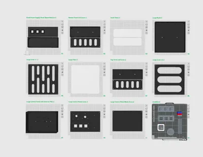
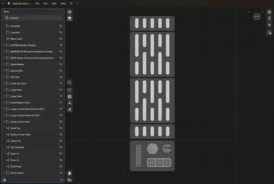
Print Profile(2)









Description
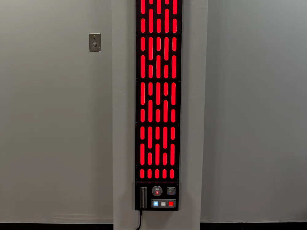
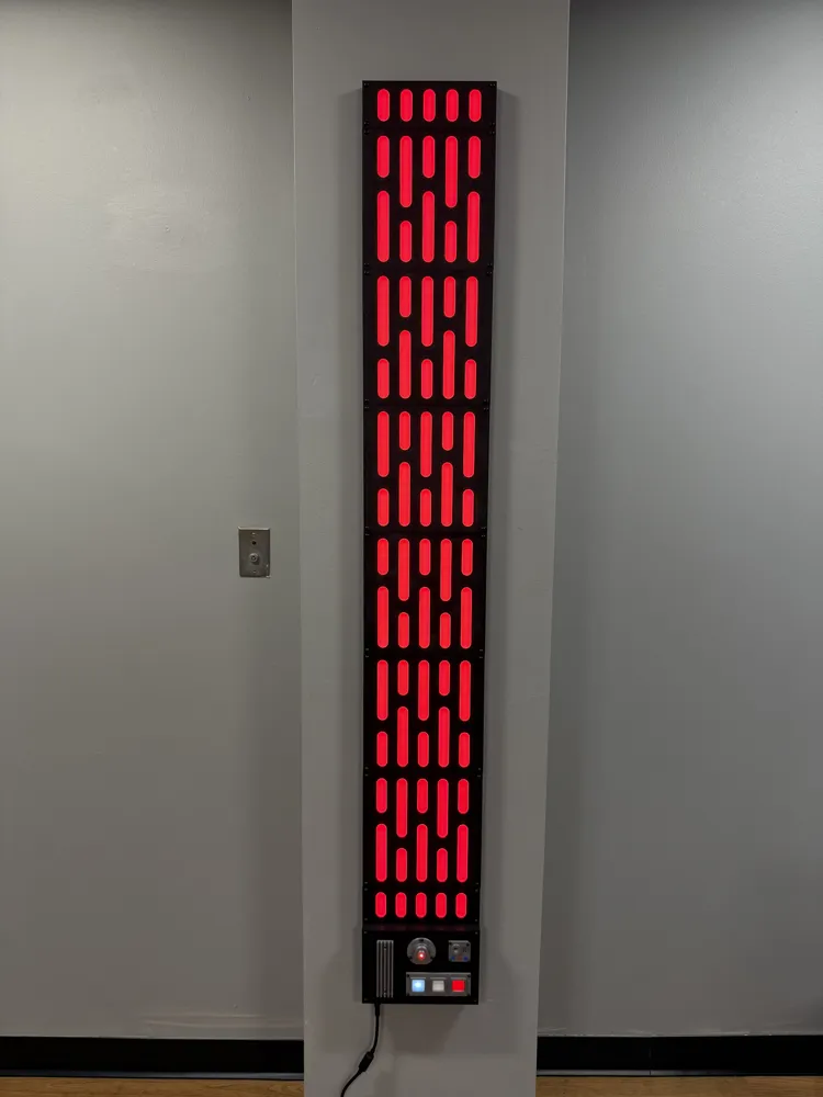
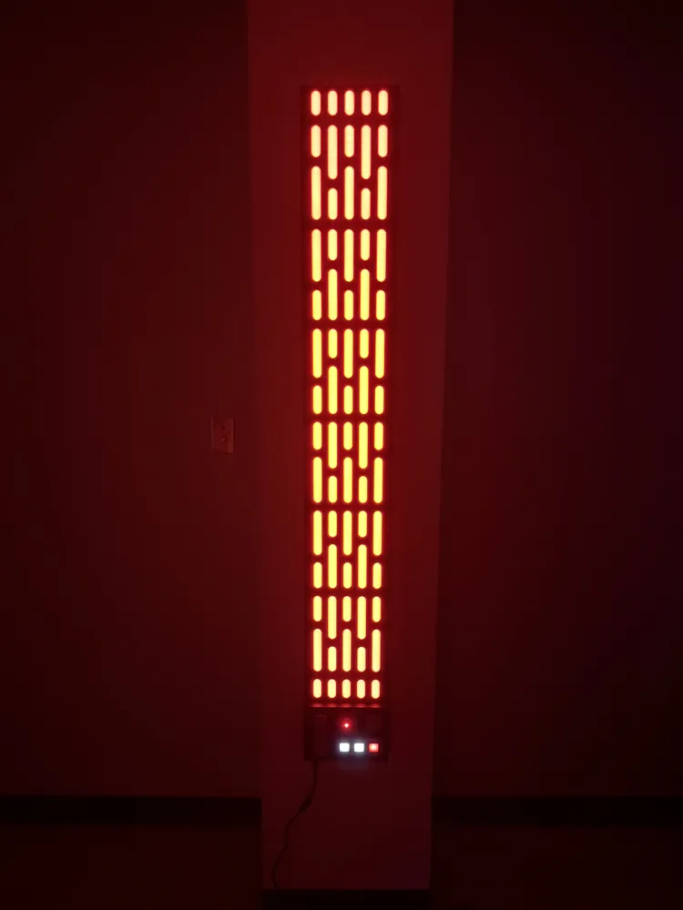
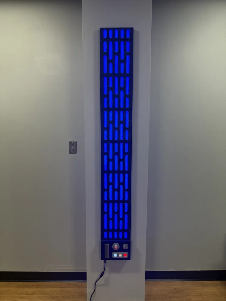
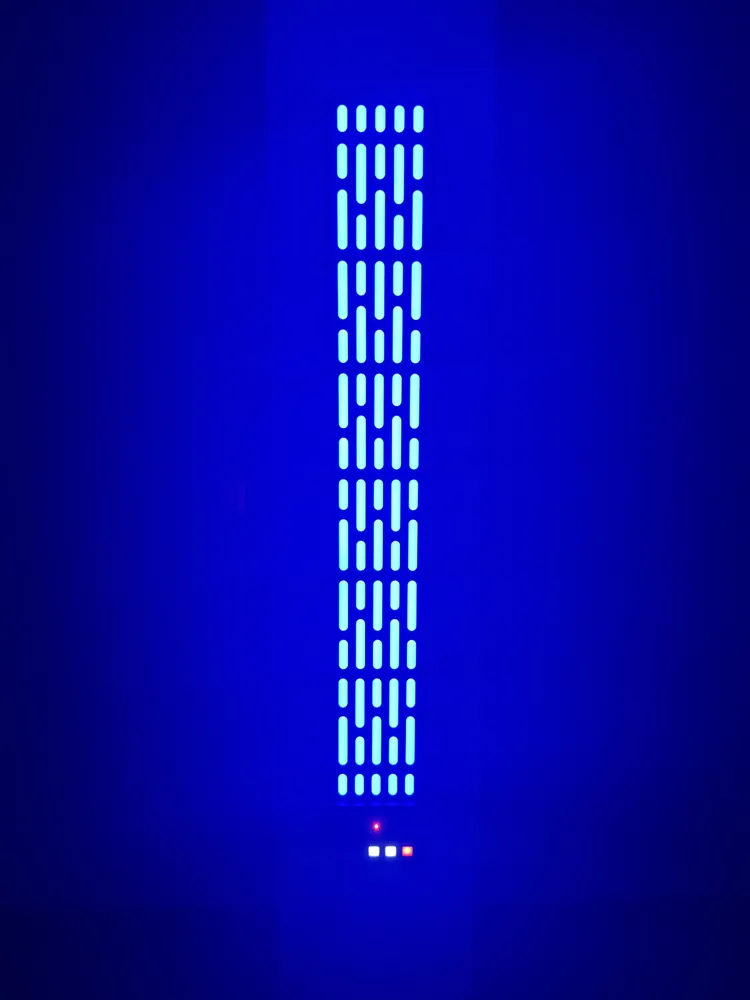
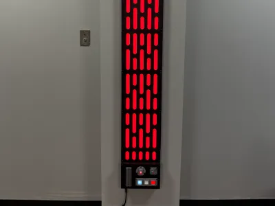
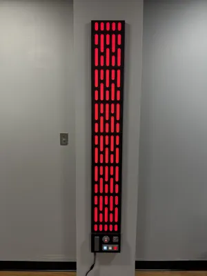
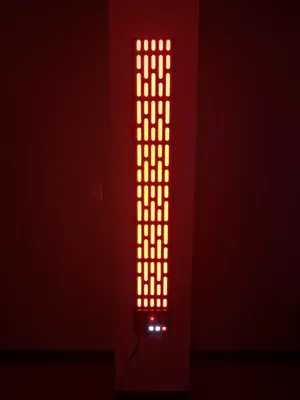
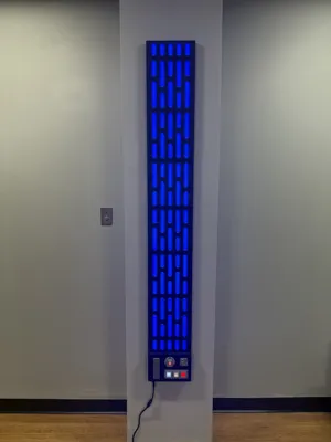
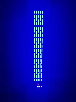
This modular Death Star-inspired light panel system features fully 3D printable or laser-cut parts designed to fit a Bambu Lab X1C build plate. The panels are illuminated with 12V WS2811 addressable LEDs and controlled by an ESP32 running WLED. The system supports five LED strips, optional audio reactivity via an INMP441 microphone, and customizable lighting through added button greeblies. All panels are stackable and connected with threaded inserts and screws for a clean, expandable installation.
Death Star Light Panel Build Guide
Included Files
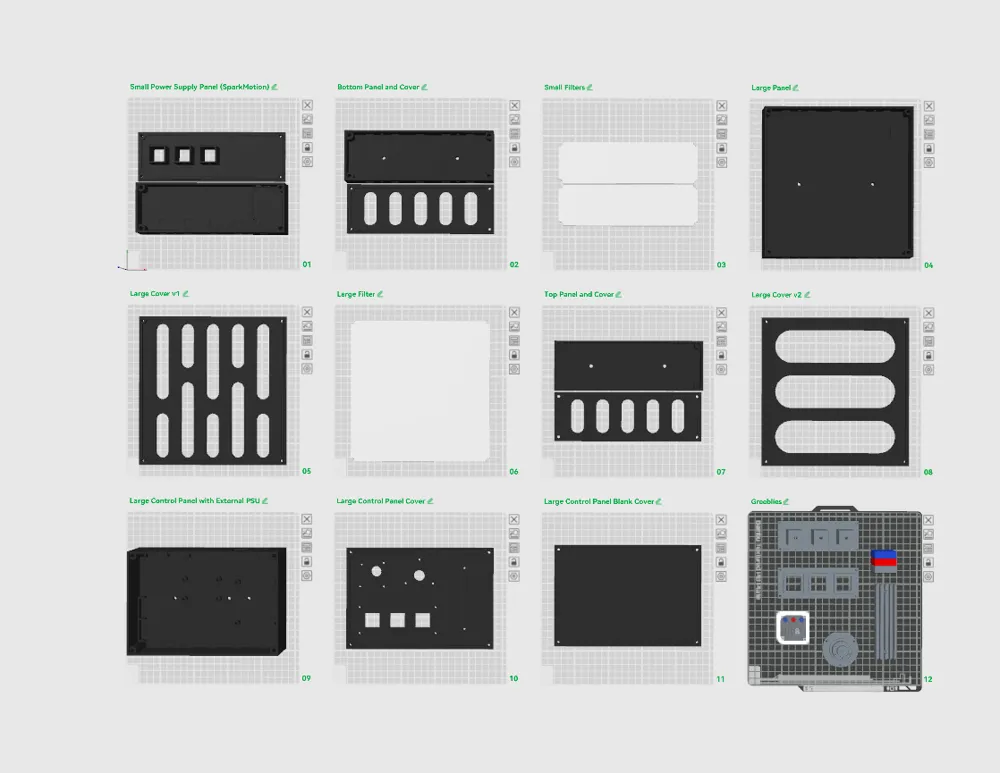
- STL files – for full 3D printing (panels, covers, LED filters, control housing, greeblies)
- DXF files (optional) – for laser cutting panels and LED filters from 3mm acrylic
Panel Types
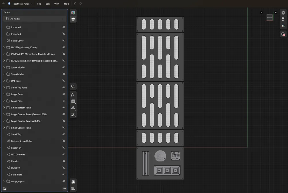
- Small Light Panel
- Large Light Panel - two design versions included
- Control Panel - houses electronics and power input
Materials
Fasteners
- M6 × 12mm screws x2 per panel connection
- M6 nuts x2 per panel connection
- M4 heat-set threaded inserts x4 per panel - for attaching covers
- M4 × 8mm screws x4 per panel – for attaching covers
- M3 heat-set threaded inserts x8 – for mounting electronics in the control panel
- M3 × 5mm screws x8 - for securing the ESP32 and buck converter
- M3 x 12mm screws x13 - for optional greeblies
- M3 Nuts x13 - for optional greeblies
Connectors & Components
- 12V 180W power supply x1 - powers ESP32 and all LEDs
- Wago 221-415 5-port lever connectors x4 for distributing 12V and GND inside the control panel
- 5.5mm × 2.5mm DC barrel jack x1 - mounted to the control panel for external power input
- Rocker switch x1 - inline with the barrel jack for power
- JST-XH connectors x5 - optional for quick disconnects of LED strips
Electronics
- ESP32 microcontroller x1 – controls LED animation, one data pin per strip
- WS2811 12V addressable LED strips x2 - - cut into 5 strips of desired length
- Buck converter x1 – powers the ESP32 from the 12V supply. Lower to 5V output.
- 330–470Ω resistors x5 – one on each data line between ESP32 and LED strip
- INMP441 12S MEMS Micophone x1 - optional sound reactivity
- 12V 5mm Solid White LEDs x2 - optional lights for greeblies
- 12V 5mm Blinking LEDs x1 - optional lights for greeblies
Assembly Instructions
1. Prepare and Join Panels
- Print the desired number of panels for your project. For the project pictured:
- x1 small top Panel, cover, and filter
- x6 large panel, cover, and filter
- x1 small bottom panel, cover, and filter
- x1 control panel and cover
- Install M4 heat-set inserts into the corner holes of each panel.
- Use M6 × 12mm screws and nuts to bolt panels together.
- Glue filters onto LED panel covers.
- Greeblies (optional)
- Buttons
- Insert buttons into the top button housing.
- Attach on to the top of the control panel cover with four M3 x 12mm screws.
- Secure the bottom button housing on the opposite side of the cover with four M3 nuts.
- Glue three 12V 5mm LEDs into each hole on the bottom button housing.
- Microphone
- Attach the top microphone housing on the top of the control panel cover with four M3 x 12mm screws.
- Insert the INMP441 I2S MEMS Micophone
- Secure the bottom microphone housing on the opposite side of the cover with four M3 nuts.
- Hard Drive
- Attach to the top control panel cover with three M3 x 12mm screws.
- Greeblie v1
- Attach to the top control panel cover with three M3 x 12mm screws.
- Buttons
- NOTE: A blank control panel has been included for your own customizations.
2. Prepare the LED Strips
- Channels are designed to fit LED strips up to 12mm wide.
- Purchase the required number of 16.4ft (5m) WS2811 12V LED strips (300 LEDs each) and cut to length. For the project pictured:
- Two packs of 16.4ft (5m) WS2811 12V LED strips (300 LEDs each)
- Cut into 5 strips of 88 LEDs.
- Solder wire leads (power, ground, data) to each strip before installing.
- Use 2.54mm JST-XH connectors for easy plug-and-play wiring.
3. Install LED Strips
- Thread each strip through the joined panels and adhere in place.
- Ensure all strips are secure before continuing.
- Install LED panel covers with M4 x 8mm screws.
4. Assemble the Control Panel
- Install M3 heat-set inserts (8 total) for electronics.
- Mount ESP32, buck converter, Wago connectors, barrel jack, and rocker switch using M3 × 5mm screws.
5. Complete Wiring
- Connect DC barrel jack
- 12V → Off
- GRD → GRD Wago
- Connect rocker switch
- On → 12V Wago
- Adjust buck converter to 5V and connect to the ESP32
- VIN → +
- GRD → -
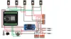
- Connect each LED strip's data line to ESP32 GPIO pins with inline 330–470Ω resistors.
- Data GPIOs:
- Strip 1 → GPIO 33
- Strip 2 → GPIO 25
- Strip 3 → GPIO 26
- Strip 4 → GPIO 27
- Strip 5 → GPIO 12
- Data GPIOs:
- Connect INMP441 I2S MEMS Micophone (optional)
- L/R, GND → GND wago
- VDD → 3.3V on ESP32
- SD → GPIO 21
- WS → GPIO 19
- SCK → GPIO 18
- Connect 12V 5mm LEDs to 12V and ground Wago terminals (optional)
- Use 2.54mm JST-XH connectors for easy plug-and-play wiring.
6. Final Steps
- Attach the control panel to the bottom of the panel array.
- Plug everything in, test functionality, and mount to the wall.
ESP32 Pin Configuration (WLED Setup)
1. Install WLED
- Remove ESP32 from the breakout board and plug it into a computer
- Install WLED
- Reinstall the ESP32 into the breakout board.
2. WLED Setup
- Setup LED strips
- On your computer navigate to WLED IP address.
- Go to: Config → LED Preferences → LED Outputs
- For each of the 5 LED outputs:
- Type: WS281x
- Max current per LED: 30 mA
- Color Order: BRG
- Length: 88
- Data GPIOs:
- Strip 1: GPIO 33
- Strip 2: GPIO 25
- Strip 3: GPIO 26
- Strip 4: GPIO 27
- Strip 5: GPIO 12
- Save
- For each of the 5 LED outputs:
- Setup Microphone (optional)
- Go to Usermods → AudioReactive, click Enable.
- Then under Digital Mic, select Generic I2S.
- Set the following pins:
- I2S SD: 21
- I2S WS: 19
- I2S SCK: 18
- Save and power cycle ESP32
- NOTE: Compatible effects will be designated with a musical note icon.
Documentation (1)
License

You shall not share, sub-license, sell, rent, host, transfer, or distribute in any way the digital or 3D printed versions of this object, nor any other derivative work of this object in its digital or physical format (including - but not limited to - remixes of this object, and hosting on other digital platforms). The objects may not be used without permission in any way whatsoever in which you charge money, or collect fees.


Comment & Rating (107)