


Print Profile(1)

Bill of Materials
- Modulo di irrigazione automatica Kit fai da te x 1: https://it.aliexpress.com/item/1005007250750722.html?spm=a2g0o.order_list.order_list_main.10.58f43696W23JxZ&gatewayAdapt=glo2ita
Description
Boost Me (for free)
Lend a hand in bringing complex projects like this to life!
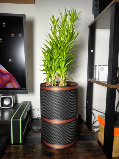
SmartPot
Add a touch of elegance to your garden, office, or living room with this self-watering smart planter. Never worry about watering your plants again—it does it automatically.
Easy to print and assemble with the guide below.
The electronics kit was purchased on AliExpress at this link:
I don’t have an Amazon link, but simply search for “automatic irrigation module” in the search bar, and you’ll find the same kit I used.
Assembly Instructions:
Caution: You can choose three ways to power the planter:
- Battery pack only.
- USB power only.
Battery pack + USB power.
The third option requires certain precautions to avoid damage.
The battery pack and the USB cable CANNOT be connected simultaneously.
Unfortunately, this inexpensive kit has this assembly limitation. If an updated kit becomes available, I will update this page.
To avoid risks, use either the cable or the battery pack. If you choose the battery pack, I recommend rechargeable batteries, as the lifespan of standard batteries may be quite short.
The following instructions explain how to connect both the battery pack and the USB cable. If you want to omit one, skip the relevant steps. (If you are unsure about the procedure, leave a comment, and I will respond as soon as possible).
 | 1. The purchased kit includes the following components:
|
 | 2. Connect the supplied cable to the moisture sensor. |
 | 3. Insert the cable into the hole on the right. |
 | 4. Place the battery pack in its compartment, guiding the wires through the designated hole. |
 | 5. You should now be at this stage. |
 | 6. Take the supplied wire kit and separate the black and red wires and a wire of your choice—I used brown. |
 | 7. Cut the black and red wires in half. |
 | 8. Take the first electronic board, which converts the analog signal from the moisture sensor into a digital signal. Connect the sensor wires to the side with two pins and the black, red, and brown wires to the other side, respectively, to the pins marked GND, VCC, and D0. In summary: Red wire → VCC Black wire → GND Brown wire → D0 (Caution: The pin positions may differ from the image; follow the markings on the board). |
 | 9. Cut a piece of double-sided tape and apply it to the back of the board. If you don’t have double-sided tape, you can use hot glue or any non-conductive adhesive. |
 | 10. Glue the board into the right-hand compartment. |
 | 11. Turn the planter upside down and insert the pump tube and cable into the holes as shown. |
 | 12. Take the lower part of the planter and place the pump in its designated location. (Caution: To take the photo correctly, I had to remove the top part of the planter). |
 | 13. Take the relay and connect the cut red and black wires we set aside to the VCC and GND pins, respectively. For now, do not connect the brown wire. |
 | 14. Take the supplied USB cable. |
 | 15. Cut the end of the cable. |
 | 16. Strip the wires as shown. |
 | 17. Strip the red wires except for the red wire from the pump and join them together. The wires to be connected are:
|
 | 18. Insert the connected wires into the central port and the red wire from the pump (excluded in the previous step) into the NC port. |
 | 19. Take all the black wires and twist them together. (Caution: The blue wire in the photo is the USB cable wire; it might be other colors like blue or brown). |
 | 20. Seal them using heat-shrink tubing or insulating tape. |
 | 21. Glue the relay into the compartment using double-sided tape or adhesive and connect the brown wire to the IN pin of the relay. The result should be as shown in the photo. |
PAY CLOSE ATTENTION TO THE NEXT STEP!!!
 | 22. Follow this step if you have decided to connect both the USB cable and the battery pack together:
|
 | 23. Place your plant in the pot. |
 | 24. Insert the moisture sensor into the soil. |
 | 25. Use the tube holder to secure the tube to the soil. |
 | 26. Insert the holder into the soil. |
 | 27. Add water to the base of the planter; it holds about one and a half liters. The first time, you may need to fill it twice if the soil is dry. |
 | 28. Adjust the sensor sensitivity as desired with a screwdriver. Counterclockwise decreases sensitivity (resulting in moister soil), and clockwise increases sensitivity (resulting in drier soil). Your SmartPot is ready!! |
Cultivate and enjoy with ease!
License
You shall not share, sub-license, sell, rent, host, transfer, or distribute in any way the digital or 3D printed versions of this object, nor any other derivative work of this object in its digital or physical format (including - but not limited to - remixes of this object, and hosting on other digital platforms). The objects may not be used without permission in any way whatsoever in which you charge money, or collect fees.
Comment & Rating (55)