Search models, users, collections, and posts
QuinLED DigQuad Case for WLED addressable LEDs
IP Report


Print Profile(1)

0.12mm layer, 2 walls, 15% infill
Designer
13.4 h
6 plates
Open in Bambu Studio
Boost
61
152
5
11
75
28
Released
Bill of Materials
Bambu Filaments
Select all


List other parts
- DigQuad x 1:
Description
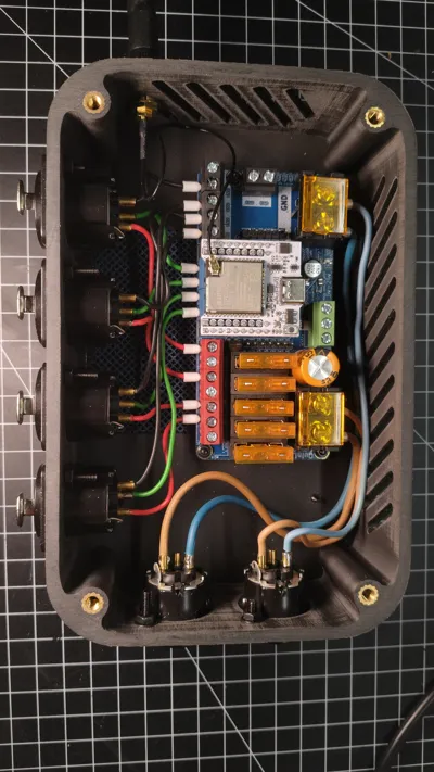
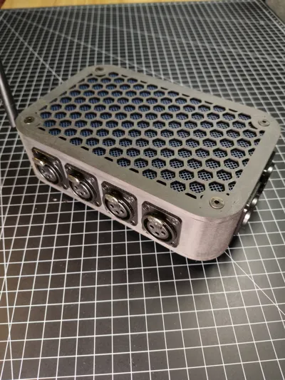
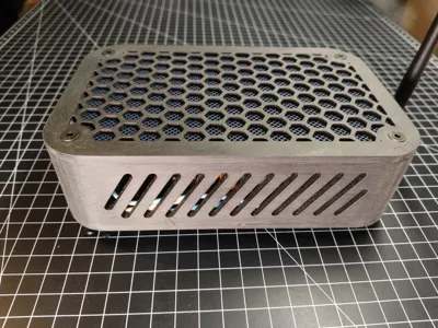
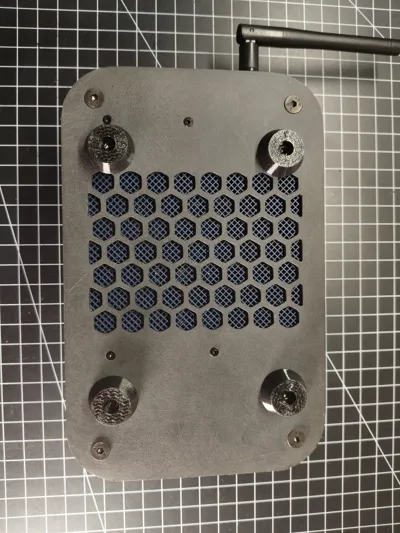
This is a modern and solid case for the QuinLED DigQuad micro controller. It features XLR connectors as they are really sturdy and reliable. It is designed to control addressable LED strips like WS2812 and SK6812.
Required hardware:
- 1 QuinLED DigQuad micro controller with external antenna
- 8 countersunk screws M4x16
- 8 heat set inserts M4
- 12 M3x12 countersunk screws
- 12 M3 washers
- 12 M3 nuts
- 4 M2x12 countersunk screws
- 8 M2 washers
- 8 M2 nuts
- 4 3x12 countersunk wood screws
- 4 XLR panel connectors 3 pin female (I used Neutrik NC3 FD-LX-B)
- 2 XLR panel connectors 3 pin male (I used Neutrik NC3 MD-LX-B)
- some wire
Printing:
- All the parts are quite easy to print. I used Bambu Lab PLA Matte for the main parts and Bambu Lab TPU 95 HF for the standing feet, but many other materials should work too.
- My Bambu Studio file is designed for really high quality and very sturdy parts. Of course you can change your settings according to your needs.
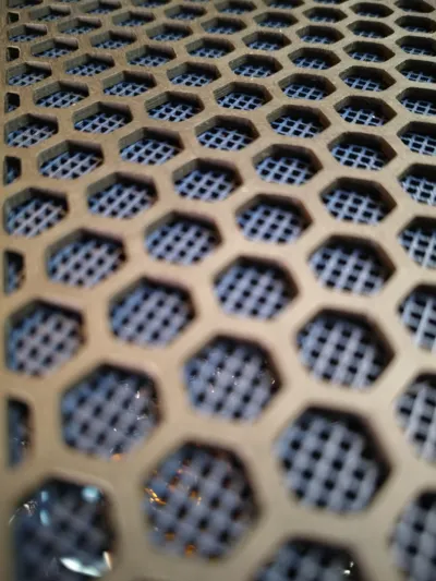
- the inlays have to be printed with modified parameters:
- layer height: 0.15mm
- wall loops: 0
- top shell layers: 0
- bottom shell layers: 0
- sparse infill density: 45%
- spare infill pattern: grid
- After printing you should sand all visible parts for a uniform and matte finish. I used 120 and 180 grid sanding paper.
- Use a drill bit to recut all holes to fit the size of the screws. This helps to create really clean holes.
Assembly:
- Press the heat set inserts into the mounting holes of the middle part using a soldering iron.
- Solder wires to the XLR connectors. Use different colors for +, data and -. Keep the wires long enough so you can later cut them and connect them to the controller. Use thick enough wires as the DigQuad can handle up to 20 amps.
- Mount the XLR connectors to the middle part of the case using the M3 screws, washers and nuts.
- Mount the external antenna to the middle part of the case.
- Glue the inlays into the top and bottom part using some superglue or plastics glue.
- Mount the micro controller to the bottom part using the M2 screws, washers and nuts.
- Put the middle part with the XLR connectors on top of the bottom part and wire everything up. Don´t forget to connect the antenna to the ESP32.
- Fasten the bottom and top part to the middle part of the case using the M4 screws. Countersink the screw holes to make the screws fit even better.
- Mount the standing feet to the case using the 3x12 wood screws. Be careful not to fasten it to tight as it might drill into the PCB of the controller.
- Equip your power supply with a 3 pin female XLR connector to power the controller. The QuinLED DigQuad controller supports voltages from 5V to 24V DC up to 20 amps. You can connect two power supplies to split the load.
- Equip the LEDs you want to control with 3 pin male XLR connectors. Make sure the pinout of the LEDs and the controller are the same.
- Connect the controller to your Wi-Fi and you are ready to control your LEDs with WLED.
License
This user content is licensed under a
Creative Commons Attribution-Noncommercial
Comment & Rating (5)