
Print Profile(6)


Description

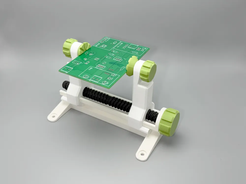
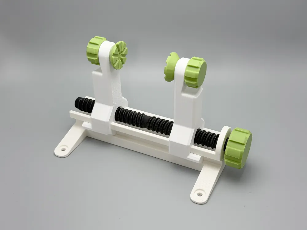
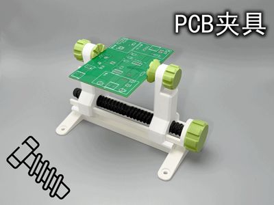
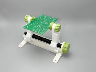
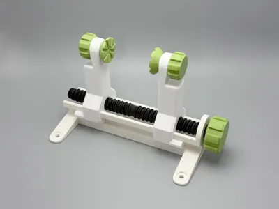
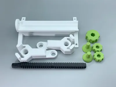
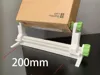
This model is a PCB fixture with a clamping range of 0-95mm and dimensions of 175*100*110mm
It features ease of use, fast printing, no supports required, and is very sturdy
Features:
- No supports required, fast printing, only 4h printing time, 100g filament usage
- Super large clamping range of 0-95mm, suitable for most circuit boards
- Differentiated tolerance fit, stable and reliable in use, the clamping surface adopts a circular micro-movement design to compensate for slight tilting of the support rods

- Bi-directional thread design, D-type horizontal printing, opens and closes quickly and smoothly, and is exceptionally sturdy, will not break
- The texture of the clamping area is designed through multiple tests, extending the opening to accommodate circuit boards with a thickness of 3mm or less
- Developable design, the clamping surface can be replaced with various different clamping surfaces according to the usage scenario to achieve different functions (users with ideas can design and use it themselves)
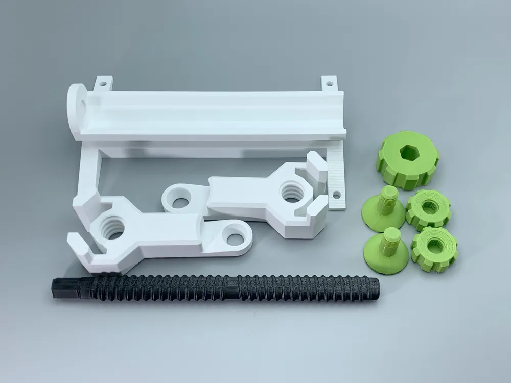
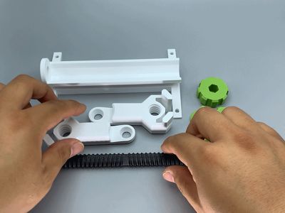
- When installing, the internal threads of the two clamps are in opposite directions; if you find it doesn't turn, you can switch the direction. Then turn both clamps to the middle of the bolt (important), and then proceed to the next installation step (otherwise, it will affect the clamp's zero position).

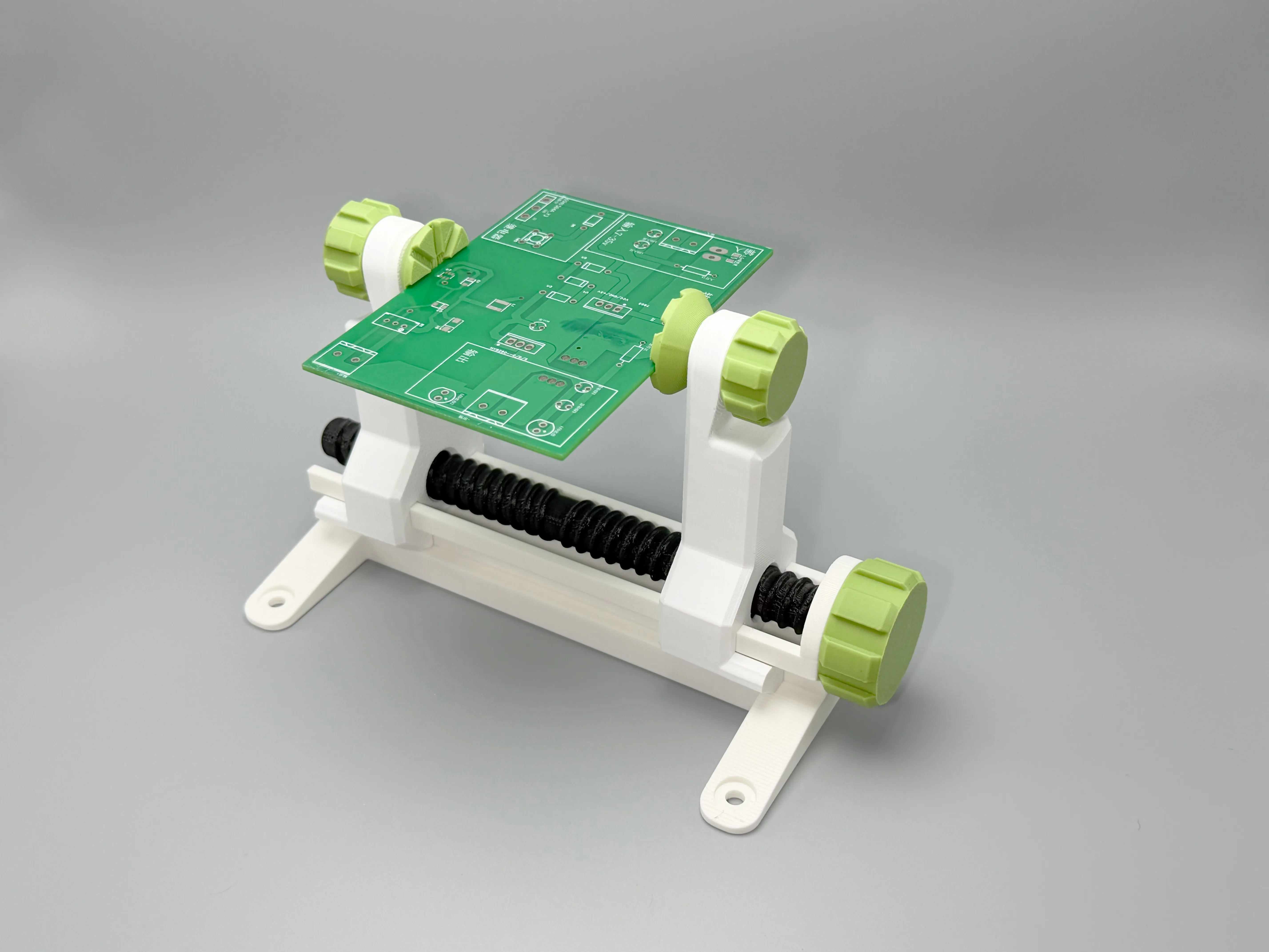
*This model, from design to completion, is engineered for FDM 3D printer characteristics, ensuring all parts require no supports, and stress directions are calculated to be in the strongest orientation;
*The internal threads of the two clamps are opposite; if you find it doesn't turn, you can switch the direction, turn both clamps to the middle of the bolt, and then proceed to the next installation step (otherwise, it will affect the clamp's zero position).
*It is recommended to use glue to fix the main shaft nut for the most durable tool.
*This model was created to solve the problem of soldering taller PCBs that require rotation. After designing multiple models and conducting extensive testing (tolerance tests, functional tests, and appearance design), this final model was chosen, and we hope you like it!
*2025.10.14 modification: A more rounded base, enhancing aesthetics and solving the issue of bumping hands.
| 2025.4.18 Added: Phone holder upgrade part | 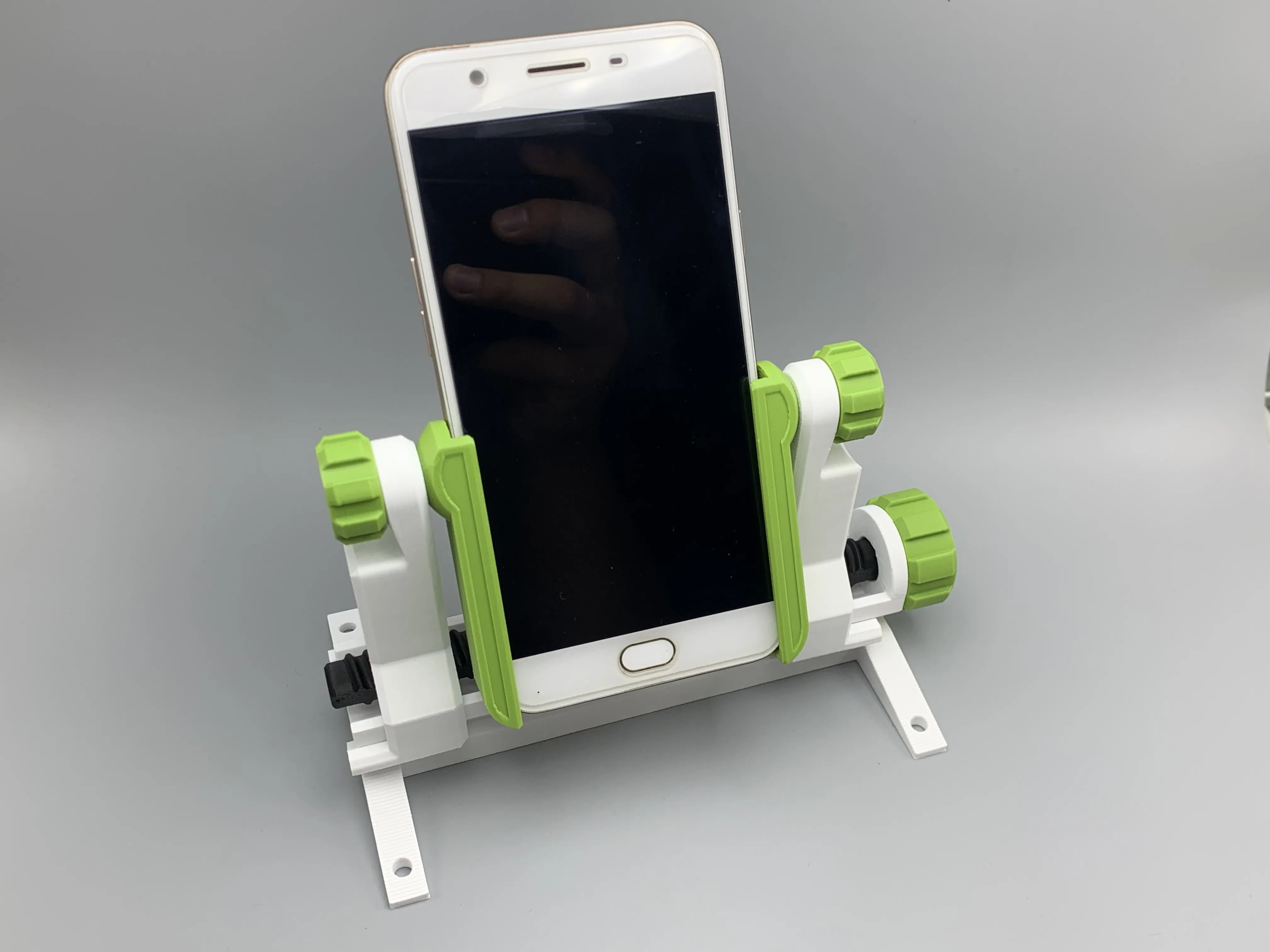
|
| 2025.9.14 Added: PCB clamping jaw upgrade part | 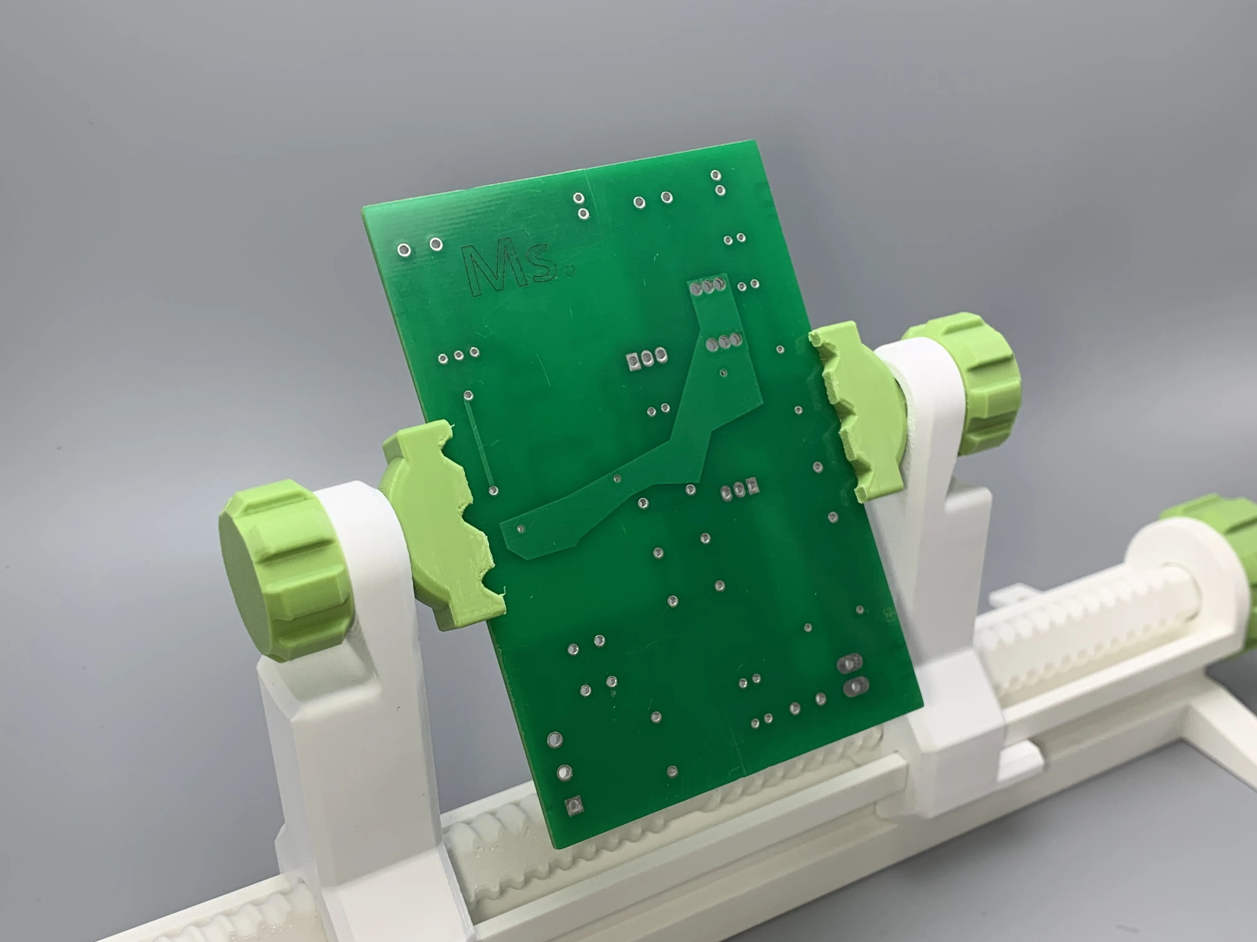 |
Another PCB fixture:
https://makerworld.com/zh/models/1874519-pcb-fixture#profileId-2006669 | 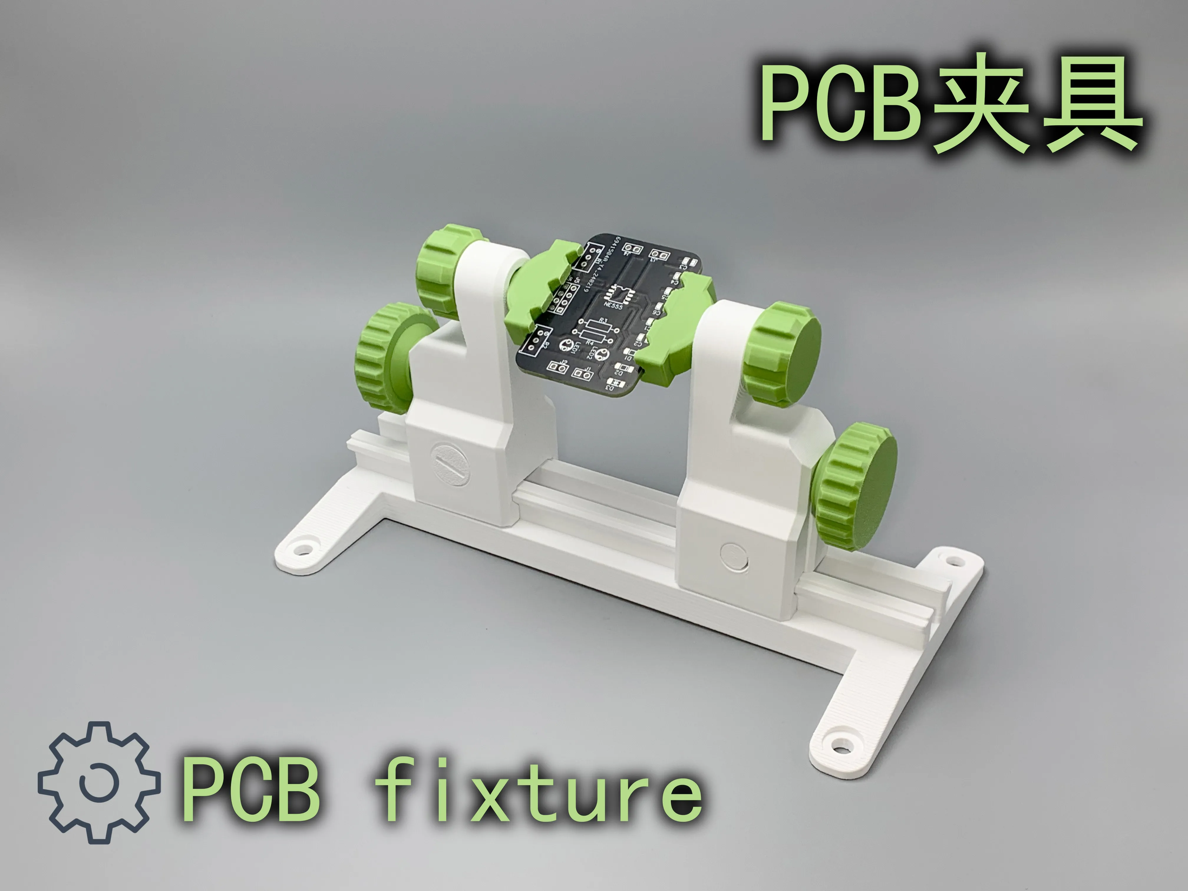 |
License

You shall not share, sub-license, sell, rent, host, transfer, or distribute in any way the digital or 3D printed versions of this object, nor any other derivative work of this object in its digital or physical format (including - but not limited to - remixes of this object, and hosting on other digital platforms). The objects may not be used without permission in any way whatsoever in which you charge money, or collect fees.


Comment & Rating (686)