Search models, users, collections, and posts

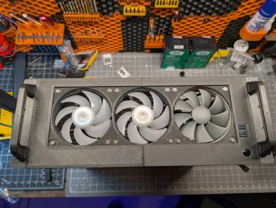
Rosewill RSV-R4100U Replacement Front Panel
IP Report
Print Profile(1)

0.2mm layer, 0.4mm nozzle
Designer
7.4 h
4 plates
Open in Bambu Studio
Boost
9
13
1
1
21
8
Released
Description
Please comment, rate, and post a make!
Be sure to check out my other models!
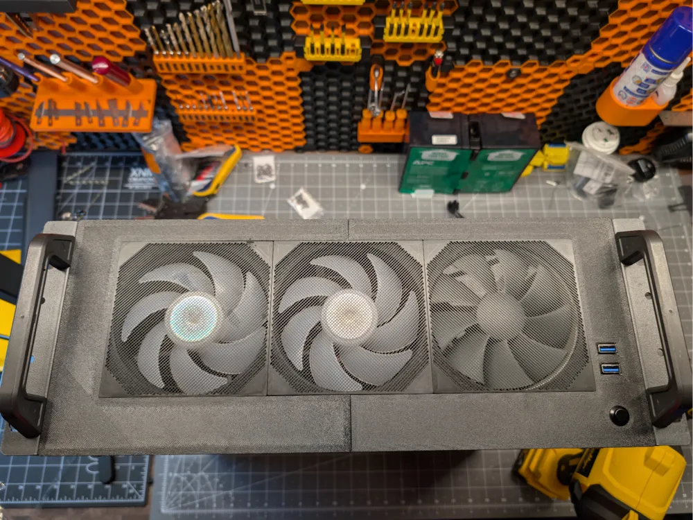
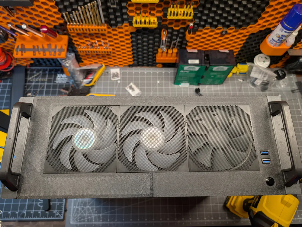
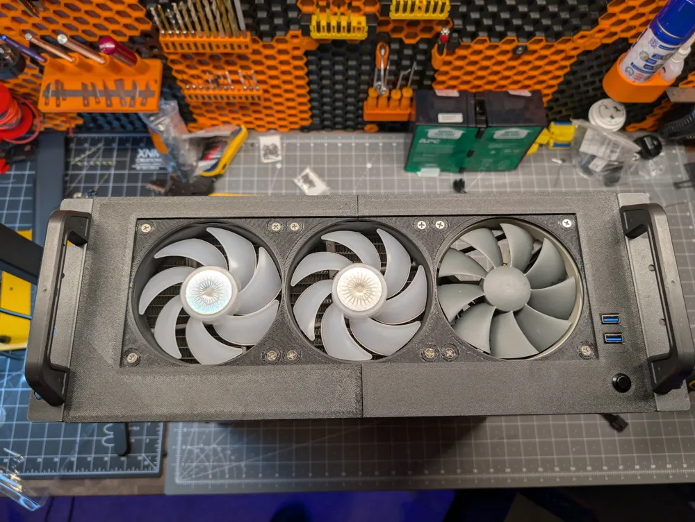
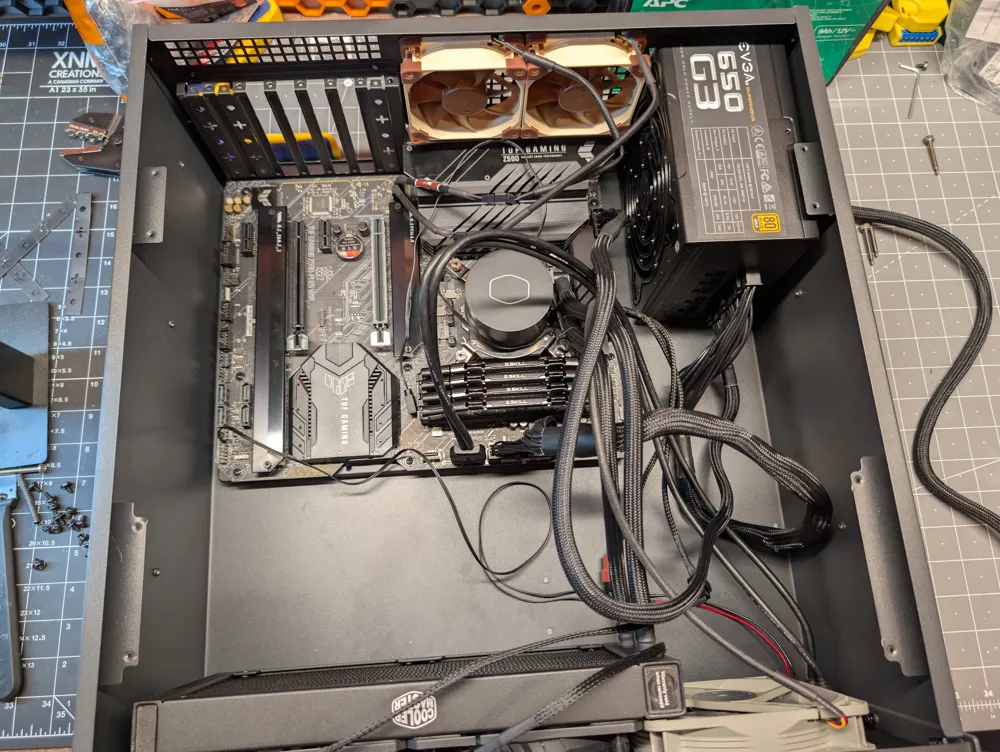
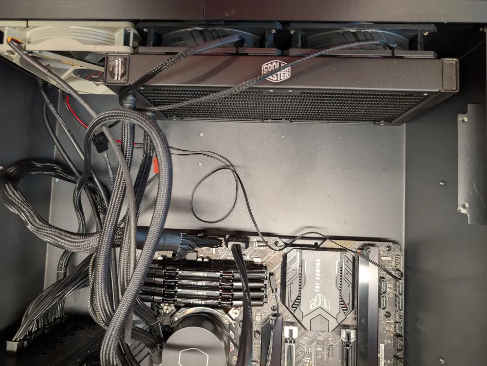
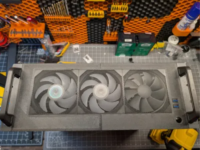
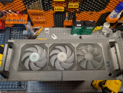
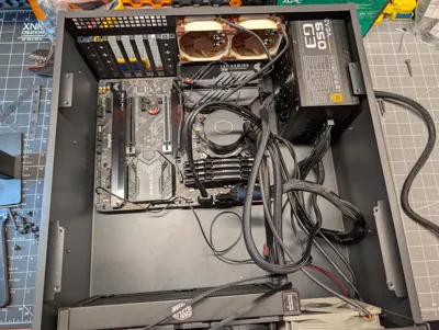
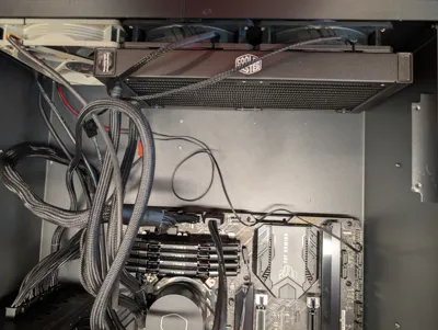
This is a replacement front panel for the Rosewill RSV-R4100U server chassis. The original panel only allows for a single intake fan and front mounted 5.25" drives/accessories. This replacement panel will allow for mounting 3x120 mm fans retaining the original USB plugs. Also included is a mounting bracket to be able to reuse the 3.5" drive bay that comes with the unit.
BOM:
M3 screws - assorted lengths
M3 inserts - 6mm or less
M2 countersunk screws and nuts
12mm push button - make sure it's not a latching one
Fans
Printing:
- Panels and bracket:
- 6 walls
- 15% gyroid infill
- Fan cover:
- You'll definitely want to use a smooth plate and glue as a release agent or the infill will likely break. Make sure you let the build plate cool down before trying to remove.
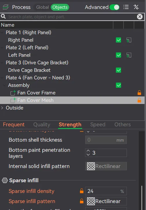
- This is semi-customizable. You can adjust the infill pattern and density of the “Fan Cover Mesh” object to change the mesh design to whatever you want.
- 6 walls for the frame
- 4 walls for the mesh
- 24% rectilinear infill
Remove OE Front Panel:
- Remove the top cover.
- Remove the two cages.
- Remove the mounting ears (3 screws each).
- Drill out the rivets:
- There are two under each handle
- Four along the bottom front edge
- Two on the bottom, perpendicular to the front at about the mid point (these hold a bracket for the two cages.
- Pull the front panel off and remove the OE bracket.
Assembly Front Panel:
- Two M3 screws to join the two front panels using the tabs at the top and bottom.
- 15-20mm long screws
- Two M3 inserts into the round mounting tabs for the USB ports.
- Attach the USB ports using m3 screws.
- Attach all three fans.
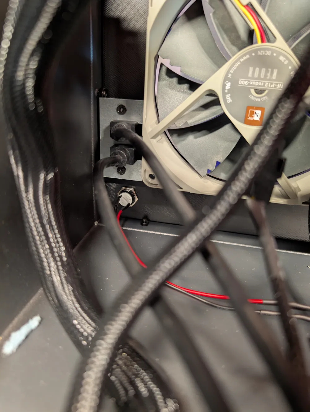
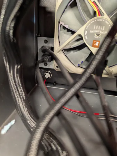
- Add your power switch.
Assembly - Mounting Bracket:
- Just add M3 inserts to each hole.
Assembly - Fan Covers:
- Each hole gets a 10x2mm magnet.
Installation:
- Slide the front panel on. The power button should be in the bottom right when facing the chassis.
- Use M2 screws and nuts where the rivets were to attach the front panel.
- For the mounting bracket, use two m3 screws from the bottom to mount it standing up. The wider part of the mount is the top.
- Add the 3.5" drive cage back in. Reuse the factory screws for the outer bracket and M3 screws for the inner side on the 3D printed mount.
- Readd the mounting ears if desired. I opted to throw a nut onto the screws since there's hardly any thread engagement through the thin sheet metal.
- I opted to cut and splice the button wires to the motherboard headers that came with the case. The polarity doesn't matter. You could also crimp them, use a level nut, twist them together with some electrical tape (not recommended), make a magnetic connector, etc..
License

This user content is licensed under a
Creative Commons Public Domain


Comment & Rating (1)