
CyberBrick Test Housing-Receiver
Print Profile(1)

Bill of Materials


Description
Boost Me (for free)
Greetings! I am a maker with a passionate dedication to design and innovation. Through 3D modeling and printing, I translate concepts into tangible realities. Your support enables me to create elegant, practical solutions! Ways to Contribute: •Experiment with My Designs: Test them and provide valuable feedback. • Spread the Word: Share my creations within your network. • Collaborate or Offer Encouragement: Your support fuels my creative pursuits! Thank you!
Related Extended Design
CyberBrick Test Housing-Transmitter(Controller)
Introduction
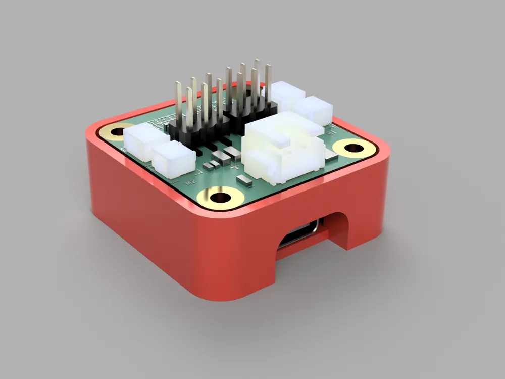
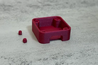
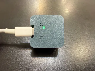
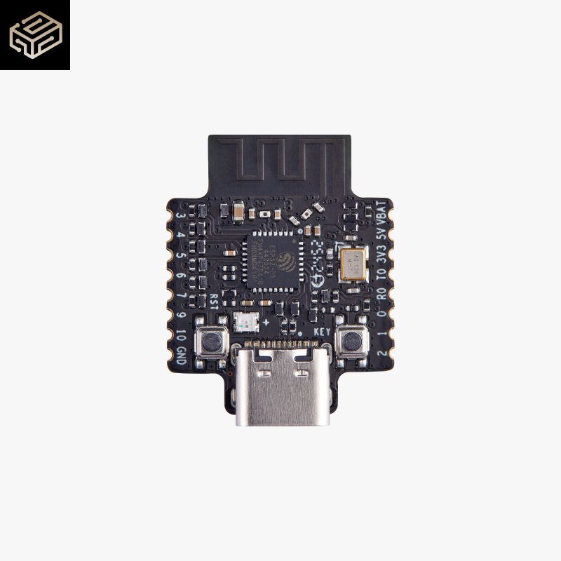
This enclosure is specifically designed for testing the Cyberbrick Receiver, providing a protective layer to prevent the PCBA backplate from coming into direct contact with metal surfaces during motor testing. It helps reduce the risk of short circuits and ensures a safer, more stable testing process.
Key Features:
- Precision fit for the Cyberbrick Receiver
- Helps prevent short circuits caused by metal contact
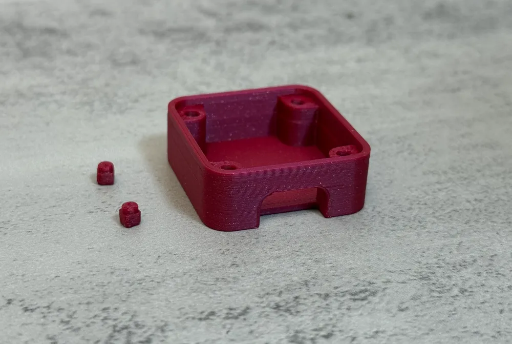
- Integrated heat-set inserts for easy, reusable fastening
- Perfect for development and test environments
- Fast and efficient 3D printing — print time stays under 18 minutes (depending on material and printer settings)
Prior to using this model, I strongly recommend calibrating your 3D printer for optimal print quality. Compensation values should be adjusted according to your printer's specifications. If you haven't already calibrated, utilize the provided calibration test piece to refine your settings. The following parameters necessitate compensation:
- X-Y Hole Compensation
- X-Y Contour Compensation
- Elephant Foot Compensation
- Precise Z Height Adjustment
For comprehensive setup instructions, consult the official guide:
Calibration Setup Guide
Changelog
All notable changes to this project will be documented in this file.
This changelog adheres to the Keep a Changelog format.
[v3] - 2025-06-22
Changed
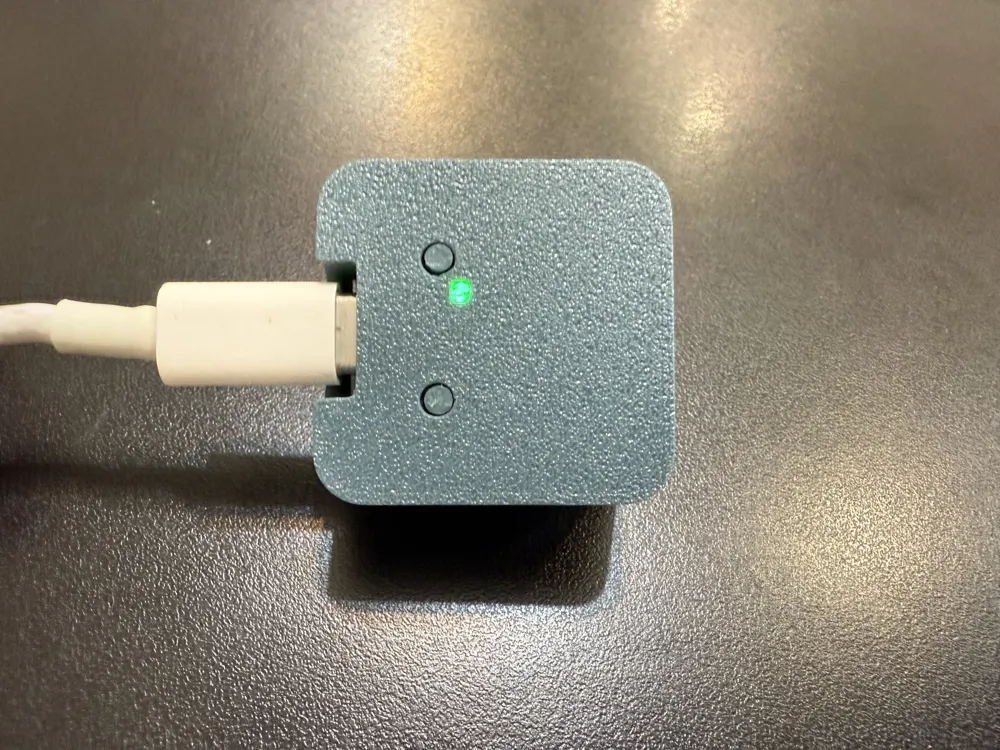
- Added an LED light guide post, enabling efficient and uniform transmission of point light sources to the outer shell surface, enhancing visibility of the Core’s operational status.
[v2] - 2025-06-14
Changed
- Fixed incorrect module height based on real module
[v1] - 2025-03-23
Added
- Initial release
☕ Enjoying the design?
If you found this design helpful and would like to support my work, feel free to buy me a coffee!
👉 https://buymeacoffee.com/shuwn
License

You shall not share, sub-license, sell, rent, host, transfer, or distribute in any way the digital or 3D printed versions of this object, nor any other derivative work of this object in its digital or physical format (including - but not limited to - remixes of this object, and hosting on other digital platforms). The objects may not be used without permission in any way whatsoever in which you charge money, or collect fees.


Comment & Rating (13)