Gort’s Head Display From Day The Earth Stood Still


Print Profile(1)

Bill of Materials

Description
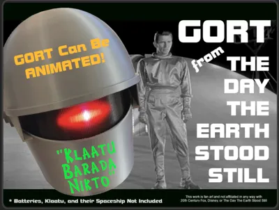
“Gort! Klaatu Barada Nikto!” (Gort, Klaatu said don't destroy the earth!) (or something like that…)
Need protection from hostile planets? A headphone/VR goggles stand? You need Gort! There's a shelf/desk mount included if you don't want to hang him on the wall.
This work is fan art and not affiliated with 20th Century Fox, Disney, or The Day The Earth Stood Still.
If you're already a Gort fan there's not much to tell you about The Day The Earth Stood Still. If you don't know who he is, he's one of the most famous movie robots of all time. He is one of an army of robot guardians who protect the solar system from aggression. They are authorized to destroy planets if a planet becomes hostile. Klaatu and Gort's mission to earth was to warn the planet that aggression against the other planets would not be tolerated.
The movie was a critical hit in 1951 and is on the US National Film Registry. Gort has become meme food and can be seen numerous places such as on the cover of Ringo Starr's Goodnight Vienna and was rumored to be behind Ronald Reagan proposing the US and Russia unite in the face of a possible alien invasion (https://en.wikipedia.org/wiki/The_Day_the_Earth_Stood_Still), and much, much more.
Sci-Fi fans believe Klaatu came from Mars (average distance around 250 million miles) and travel times on the order of 4-8 months using Hohmann transfer orbits (https://en.wikipedia.org/wiki/Hohmann_transfer_orbit) which just happens to be the shape of the servo cam that opens and closes Gort's visor! Cool, eh? Klaatu never says where he came from but the clues dropped say mars - Klaatu is a Martian.
Sound files for Animated Gort:
While this model is fan art, the original sounds from the movie are under copyright protection and I cannot redistribute them. You can rip them yourself though, and it's not hard. Instructions on how to rip and save sound files are below. On the bright side, once you know how to do it you can rip the sounds you want - not just the ones I picked for my Gort.
The Model
This model can be printed as a static display or animatronic Gort head. It’s the same download - you just don’t use all the parts for static display and you don’t use the fake servo for an animatronic. The static display Gort can still have lights and sounds too (slightly animatronic?) even if not built using all the animatronic stuff here. It’s up to you and your skill level and interest. Just don’t use high heat bits in his plastic head. Movie Gort was impenetrable and could withstand cutting torches. Plastic Gort can catch fire and burn. 🔥
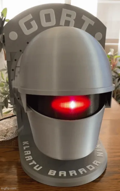
The minimum build uses the spaceship data screen to hold the top and bottom head halves together and allows hanging on a wall. To display him on a desk or shelf, print and attach the base with the Klaatu Barada Nikto text. In either mounting the Gort banner across the top is optional. The base attaches with 5 each m4x6 or m4x8 machine screws while the top Gort banner attaches with 3 m3x6 machine screws.
This model is not an exact duplicate of Gort. The original was hand made, irregular, and asymmetric if you look carefully during his closeups. This model is around ¾ full size and how Gort may have appeared right off the showroom floor instead of after destroying some number of aggressive planets. The 3-views I used came from an ebay auction of fiberglass reproductions of the original movie helmet for sale at $2700/per copy. There are some inaccuracies and liberties taken in making the 3D model but he’s pretty close and hopefully faithful to the real Gort.
There are a couple of ways to go with this model - print the head pieces in a silk silver filament or fill and paint them silver after printing - up to you. I used the recently-discontinued Bambu PLA silk silver for my head pieces. The mechanicals in the head are in black PLA to keep reflections down but that’s not required. The lens can be printed in clear translucent PLA but transparent smoke/black PLA looks more true to the movie original. The stand and data screen are in Bambu silver basic PLA (non-silk) to match the spaceship’s motif. If you paint and are animating it, keep paint off the visor pins and pivot sockets. It's close tolerance and should fall easily under its own weight when mounted on the pins in the lower head.
Colors needed are black, white, and silver basic PLA, silver silk PLA, and transparent black translucent PLA. I used all Bambu colors except for the Hatchbox translucent black PLA (UPC 849344025627) . The spaceship data screen, desk mount, and top nameplate are the only multicolor prints. The rest are single color prints that don’t require an AMS.
It's a little more complex print than normal only because there are big pieces that also need to print flat with no lifting off the build plate. For best presentation, you also want the pieces to be smooth on the exterior. One of Gort’s mysteries is how he was seamless and has attributes that cross between organic and mechanical. To get that smooth look, dry your filament well or spits and sputters can mar your Gort's glamour shots. I found that liberal use of glue stick on the cool plate kept big parts from lifting but use whatever gets you good prints.
I printed everything with a 0.4mm nozzle at a 0.2mm layer height as set in the 3mf file. The support and top shell settings have been tuned for each piece to get the best results but if you know better ways... The Bambu PLA Silk profile used to print the eye/lens pieces with Hatchbox transparent black PLA produced really good prints.
Some pieces are intentionally printed alone even though they could fit together on a plate. The reason is so the print head doesn't have to leave the part and come back. That can introduce artifacts in the print and Gort is supposed to be smooth and uniform. Also, seams/scarfs are mostly set to print on the “back” of the various prints and parts are oriented to hide them as much as possible.
Static Display Gort:
Required Parts:
11 each m4x6 machine screws
5 each m3x6 machine screws
6 each m3 pan head self-tapping screws
3 each m2 self-tapping screws (if using dummy servo to hold visor open)
For static display use what you need of the black parts (plate 2) depending how you want to display him. Visor open or closed, light behind the lens, etc. Cam 3 fits the dummy servo and it accepts an m.2 screw to hold the output cam if you want the cam to hold the visor in a particular position. Along with the upper and lower head pieces and visor, you need the data screen piece to hold the head halves together. The data screen includes a recess for a wall mount. It prints with support in it but it comes out with gentle use of needle-nose pliers, etc. The desk display foot and Gort nameplate are up to you.
Assembly is straightforward and the photos show how the parts fit together. If using the desk/shelf lower mount, attach it to the screen/backplate using 5 each m.4 machine screws. If using the Gort nameplate, attach it the the top part of the screen using 3 each m.3 machine screws.
Install the lens and LED mount into the lower head shell (you don’t really need the LED mount but it has screw flats for the end screws for the lens) using 3 each m.3 pan head self-tapping screws.
I used a light coat of “plastic-safe” synthetic polyolefin grease on the visor hinge pins but for static display you may want to glue it in place with silicone seal. Your call. Glue it in place and you don't need the other parts to hold it in a particular position. Slip the visor into position by pressing the arms together to clear the pins and expand the arms so the pin bearing in the lower head is seated. Note the visor orientation - the surface that was on the build plate faces up. Install the visor spacer (if you are using it) using 2 or 4 each m.3 screws (4 aren't really necessary).
Attach the lower head piece to the screen mount using 3 each m.4 machine screws. Don't tighten them fully. Place the alignment wafers in the pockets around the lower head piece and slip the upper head piece into position. Attach the top head shell to the screen mount using 3 more m.4 machine screws. Align the upper and lower shells and do final tightening of the all screws to keep them aligned and minimize any gaps between upper and lower head pieces.
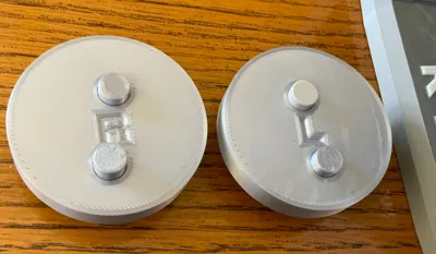
Attach the “ears” using the dowel pins and a small dab of silicone. Note - R is Gort's right and L is his left and the letters will be rightside up when properly aligned. Once you have the ears on the proper sides they only install one way to get proper ear hole alignment. You are now a member of the “other planets” for building your own Gort static display head! If you put lights inside Gort, use only LEDs - no hot incandescent lamps.
Animatronic Gort:
Required Parts:
Adafruit Prop-Maker (https://www.adafruit.com/product/5768) - $19.95 (1 each)
Adafruit 332 LEDs/meter Silicone Bead Neopixel Strip (https://www.adafruit.com/product/4865) - $37.50 (1 each)
Speaker 4 ohm, 5W, 40mm diameter (https://www.adafruit.com/product/3968) - $4.95 (1 each)
180 degree micro servo w/clutch protection (Bambu Maker Supply PG001) - $5.49 (1 each)
Wire, solder, plastic-safe grease, silicone seal, a USB-C cable and 500mA (minimum) USB-C power source
Assembly:
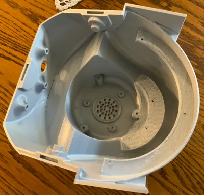
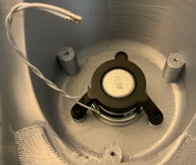
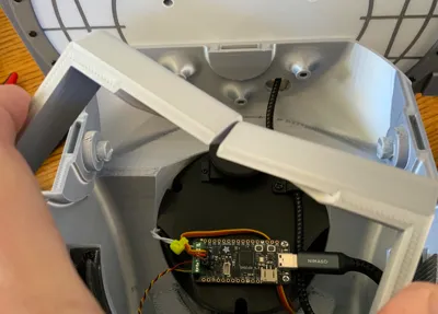
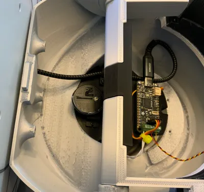
To animate Gort, prep the speaker with a few inches of wire soldered to the terminals, slip it into the holder noting orientation, and screw the holder into the base of Gort's neck over the speaker grille using three m.3 pan head self-tapping screws (see photo). Push the speaker down where the seal is resting on the ledge inside Gort’s neck.
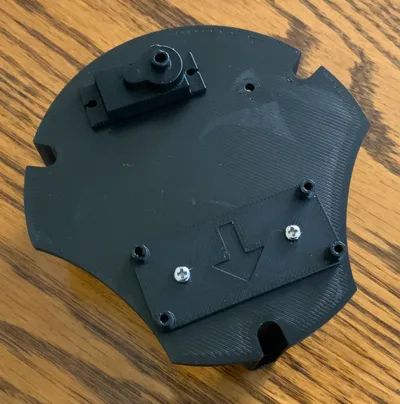
Mount the Prop-Maker board mount to the servo tray using two m.3 machine screws so the arrow points forward towards Gort's face when the tray is in final position. Mount the Prop-Maker microcontroller to the board mount using two m2.5 machine screws at the USB connector end. The mounts at the green connector end are ready for screws if you use a different version Adafruit Feather microcontroller board but only the two screws at the USB end fit with the Prop-Maker.
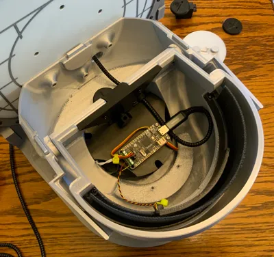
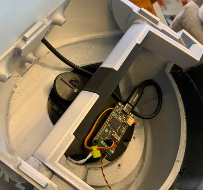
Mount the 180 degree rotation Bambu PG001 micro servo to its tray oriented as in the photos using the long screws supplied with the servo. Three pegs on the underside of the servo/Prop-Maker mount are used to wind up excess servo wire. Secure with a zip tie if needed. Route the servo wire and connect it to the Prop-Maker as shown following the color code. Mount the servo tray with servo and Prop-Maker on its mounts in Gort's neck using three m.3 pan head self-tapping screws. The output cam gets mounted later. Connect the speaker wires to the Prop-Maker screw terminals as shown in the photos.
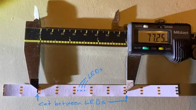
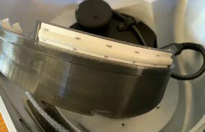
Carefully remove the neopixel strip from its silicone sleeve and cut out a segment near an end for the eye LED - 77.25mm long - with the cuts located between LED embossed locations as shown in the photo. Each square embossed in the back of the strip is a neopixel location and you want to cut between them (see photo). You want to cut at the outer edges of the three gold terminals with 6 sets of three terminals in the strip.
Add 5" color-coded light gauge wires as shown in the photo - soldering on the back using the legends printed on the front. The center terminal is the digital control signal. Double check the orientation of 5V and GND with respect to the wires and LED strip in the photo. The LED strip mounts with GND printed on the LED strip along the top of the LED holder. Carefully solder the wires to the strip, feed the wires through the hole in the LED mount, and pop the LED strip into the recess. It should fit neatly and secure once you gently flex it into place. Double check the GND and 5V labels on the LED strip are as shown in the photo and zip tie the wires to the retainer to provide strain relief for the solder joints.
Attach the lens to the head using the center screw and two end screws - m.3 pan head self-tapping screws. Tighten the center screw to hold the lens in register and then remove the end screws. Reinsert the end screws into the LED mount and tighten gently snug. Connect the LED wires as shown to the Prop-Maker board.
Screw the visor adjustment screw into the visor actuator so that about 2mm sticks out. See photos for proper orientation. Mount the visor sockets on the lower housing pegs with the surface of the visor that was on the build plate facing up. I used a plastic-safe polyolefin grease on the pegs. The visor has to fall under its own weight easily - gravity is the return spring. With the visor arms expanded, slip the visor actuator into position and secure it with two or four (two is really sufficient) m3x6 machine screws. The adjustment screw head is to the front of Gort and the screw tip should point to the back of gort. The screw tip follows the servo cam (installed later) to open and close Gort's visor.
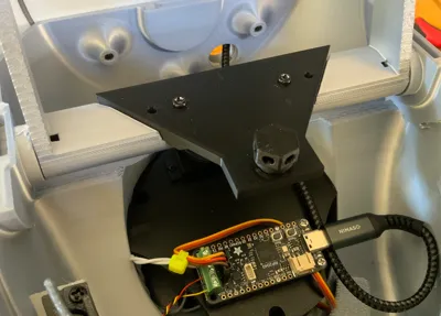
Insert the three alignment wafers into the slots in the seam area of Gort's lower head half and secure the lower head to the spaceship data screen mounting plate using 3 each m4x6 or 8 machine screws. Just tighten barely snug for now. (This step could also be done earlier if you would like a stand while you work on Gort. Without the stand - more flexible and easier to tilt as you put stuff together but tippier since the base isn't that big. Your choice.)
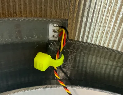
Thread a USB cable through the back of Gort to the Prop-Maker as shown. Secure with the wire clip and zip tie for pullout protection. Insert and glue (silicone seal) the plug to clean up the cable exit if desired.
At this point the top of the head is not attached and the output cam isn't mounted on the servo. Now to wake him up!
Programming:
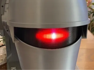
First, since RGB neopixels form Gort's “eye” you can make the eye one of several colors. There's a place in the code to pick the eye color - red, green, blue, cyan, yellow, purple, or white. According to the book “Farewell to the Master”, Gnut/Gort's eye was red. The movie was filmed in black and white but the light used was supposedly also red. So red is the default but if you want to look into the code, you can change eye color with a simple command: “color = RED”, “color = BLUE”, etc.
Plug the Prop-Maker into your computer using a USB port. The cable needs to have data capability and not just be a charging cable. You should see a drive called RPI-RP2 appear. If you don't, hold the BOOT button and press and release RESET while continuing to hold the BOOT button. When it boots into the proper mode to program it, the neopixel on the ciruit board will be white and you should see the RPI-RP2 drive attached to your computer.
Locate the UF2 file (the one with the super long name ending in .uf2) in the Gort file zip archive and drag and drop it onto the RPI-RP2 drive icon. The file will copy in and RPI-RP2 should disappear and CIRCUITPY should appear in its place. The Prop-Maker on-board neopixel should be blinking green about every 5 seconds or so. Congrats! Gort's brain is ready to accept data!
Locate the Gort files archive (GortCode.zip) in the Gort file zip archive and drop the contents onto CIRCUITPY. (Not the zip file itself - drop the contents.) It will take a short while to copy over but what you should see are the files in a directory structure just like you see in the zip archive. Congrats again! Gort now has his instructions (except for Asimov's three laws…).
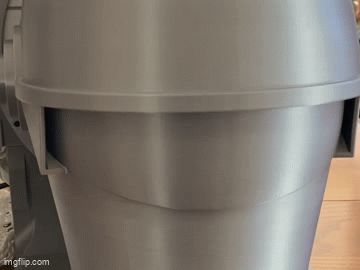
When Gort boots, the first thing he does is ask you how often he should animate. He prompts you to “tap for time” then waits for you to tap him gently. His visor gradually opens with full open equal to 60 minutes. Half open is 30 minutes. Just tap him gently when the visor is at the fraction of an hour you want between events. If he times out, the default is that he animates every 30 minutes. Tapping or timing out terminates the measurement and moves on to the volume setting.
After the tap for time between events, Gort will prompt you to “tap for volume”. Same thing - the visor will start opening and when you tap is scaled to 50% maximum volume. Gort can be loud. Manually setting the volume with taps is limited to 50% volume but set volume in the code and you can go to 100% if you want.
After setting volume, Gort starts doing his routine which is just waiting for the next animation event. During this time, a gentle tap will prompt him to end the wait and animate.
Note: The code is just a text file called “code.py” in the root directory of the CIRCUITPY drive. In there you can change the eye color and also preload time and volume settings. There are two lines that set minutes = 0 and volume = 0. When those are set to 0, Gort prompts you to set time and volume by tapping at the appropriate visor position. Want to have it chime hourly? Set minutes to 60 in a plain text editor (no special characters). Same for the volume. Want it always low? Edit the volume line to something like volume = 5.0.
If you don’t want to edit a file, there is also a directory in the CIRCUITPY root directory called “otherversions”. Those have the minutes and volume settings preconfigured but you need to delete the code.py file in the root directory and copy the code.py version with the settings given in the file name suffix into the root directory and change the name to remove the .mXXvXX suffix or CircuitPython won’t recognize it as code. It needs to be named code.py. But if any of the other versions work for you, no code editing needed. Once you’ve picked settings the otherversions directory is no longer needed and can be deleted to make more room for sound files.
Because of copyright restriction, Gort is not supplied with dialog from the movie. Instead, you get two copies of sleigh bells from the Clausometer. Two because it won’t play the same file twice in a row so two files just named different names. My apologies. I wish I could supply them but legally I cannot.
Final Assembly:
We had to program Gort to get the servo in the correct eye-closed position. Power him up and first thing he does is run the servo to the “eye-closed” position and wait three seconds. Unplug him during that wait and the servo is in proper position to secure the cam on the servo.
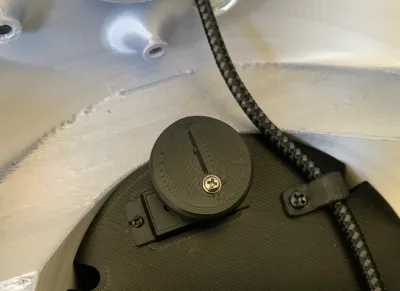
Three cams are provided to hopefully accommodate slight variations in servos. They only differ in the hole for the servo output shaft with 1 being tightest and 3 loosest. For me, Cam2 fit the Bambu servo fine. I have another micro servo (different brand) that requires Cam3. Hopefully one fits your servo. If none do, let me know and I'll create other cams with holes that hopefully fit. Note that in some cases, a little extra pressure seating the cam will get it to proper position if it is a little tight.
With the servo in the “eye-closed” position, align the cam where the line on the cam is pointing to the rear of Gort. This puts the small of the cam forward and the larger lobe straight rear towards the spaceship data screen. Gently push the cam down and secure with the smallest screw supplied with the servo.
Plug Gort back in to power him up and double check that the cam line is oriented straight back. When Gort opens the visor, check that the cam line is now oriented straight forward or close enough. If so, let him close the visor again, unplug him, and adjust the visor adjustment screw (the bolt on the brackets and fittings plate with the holes in the head) to get the visor just sitting on the lower face opening for the eye. Note that the adjustment screw has holes to allow using a small screwdriver or sturdy pin to make adjusting easier. It doesn't need to be perfect. You just want it close.
Now attach Gort's brain pan. You will need to loosen the screws holding the lower head piece to the spaceship data screen a few millimeters. With the alignment wafers in the slots in the edge where top meets bottom, the top kind of pops into place. The top head piece should drop onto the alignment wafers. Snug the screws holding the lower head to the spaceship data screen and then insert and snug the screws for the top of the head while keeping the head halves aligned and pressed together to minimize any gap.
Use small dabs of silicone seal to hold the ear pieces on with their dowel pins. R and L are Gort's right and left and the letters will be upright (and hidden) when assembled.
That's it. You have joined the people of the “other planets” who built their own Gorts too! If only they were real…
Sound Files For Gort:
It’s easy to collect wav/sound files for Gort or other projects. I just used a cheap USB headphone/microphone sound card to grab the files I needed. You can use pretty much any computer to grab audio - You just need an application to record if you don’t have one. I used Audacity. It’s free and available for Windows, Mac, and Linux. (https://www.audacityteam.org) I used a Roku to stream the movie, fast forward, etc, and a Tendak HDMI Audio Extractor from Amazon (4K HDMI to HDMI with Optical SPDIF + 3.5mm Stereo + RCA L/R Audio Adapter Converter with Volume Control Support 4K@60Hz HDCP 2.2 HDR 3D YUV 4:4:4 - ASIN B0BJPCDF5P) to actually get the signal to the USB sound card. The Tendak goes into the HDMI path between the Roku and TV and splits audio out to the USB sound card.
I would cue up the movie and play the segment I wanted to capture while recording it, and then use Audacity to trim, remove pauses, and save the clips out as 22050Hz, 16-bit signed wav files.
Once you get it set up and working to grab audio files, collect short clips you like - sound effects, dialog, and music. Personal use is broadly allowed by US copyright law. You just can’t redistribute sound collections you might create from copyrighted works - which is why I can’t provide the sounds that I ripped. IANAL so cannot advise on legalities.
With wav files, clip length is directly related to file size. You want to edit out pauses and dead spaces, keep lead-in and lead-out short, etc. There’s only around 7MB of audio storage space to work with and that gets eaten up fairly quick. I got 25 audio clips to fit on Prop-Maker which makes a nice collection and variety.
Use the 8.3 naming convention for your clips and every wav file must start with a letter. The reason is the way CircuitPython indexes the sound files. The system reserved files start with numbers and you only want to use numbers as the first character in the file name if you are replacing those files. They go in the /sounds directory on the Prop-Maker when you plug it into a computer.
Adafruit.com:
Adafruit is a huge repository of information on the boards, programming them, example files, how-to guides, videos, cool parts, etc. If you want to learn more about this and other boards, sensors, other cool projects (lots of 3D printed cosplay stuff), it’s the place to go.
License
You shall not share, sub-license, sell, rent, host, transfer, or distribute in any way the digital or 3D printed versions of this object, nor any other derivative work of this object in its digital or physical format (including - but not limited to - remixes of this object, and hosting on other digital platforms). The objects may not be used without permission in any way whatsoever in which you charge money, or collect fees.
Comment & Rating (17)