Poop Conveyor IR Controller Mod


Print Profile(1)

Description
1/26/2026 Update: A member brought to my attention that I left out how I wired this which was a complete oversight as I wired it on the fly and wrote nothing down. Thank you PCDaryl.
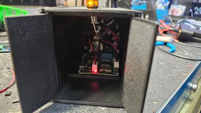
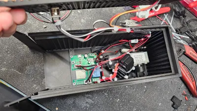
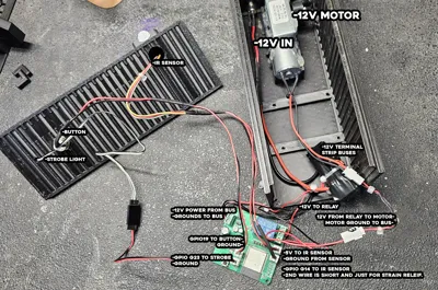
I actually have the unit torn apart right now because I’m re-doing it, so I was able to retrace everything. I’ve attached photos with labels and had Chat summarize my ramble as i took it apart to write this update.
Important disclaimer: I’m not an electrician, this isn’t an “approved” design, and this was very much a “make it work” hobby project. If you’re not comfortable working with 12 V and ESP32 GPIOs, please don’t treat this as a turnkey solution.
That said — it does work reliably, and I’ll outline exactly how I wired mine below.
Power Overview
- System is powered by a 12 V DC wall adapter
- 12 V is split using two terminal bus strips:
- One for +12 V
- One for Ground
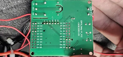
- An ESP32 relay board with built-in buck converter is used:
- Accepts 12 V input
- Generates 5 V for ESP32 + GPIO devices
- Includes an onboard relay for switching the motor
12 V Wiring
- 12 V DC input
- +12 V → 12 V bus strip
- Ground → Ground bus strip
- ESP32 Relay Board
- 12 V IN → 12 V bus
- GND → Ground bus
-(I used two ground wires here for some reason. cant remember why exactly. Please refer to aformentioned I just made it work. LOL)
Motor Power
- +12 V → Relay COM
- Relay NO → Motor +
- Motor − → Ground bus
This lets the ESP32 switch the conveyor motor on/off using the onboard relay.
ESP32 GPIO Wiring
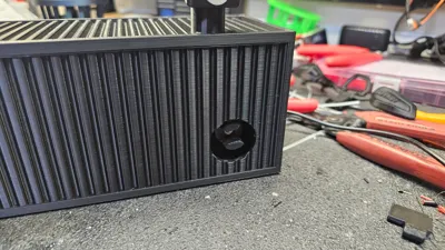
IR Sensor
- VCC → 5 V (from ESP32 board)
- GND → Ground
- Signal → GPIO14
Note: The IR sensor connector has a second short wire that does nothing electrically. It’s only there for strain relief so the plug doesn’t rip off the board.
Manual Button
- One side → GPIO19
- Other side → Ground
Configured as a simple pull-to-ground input.
Strobe Light
→ GPIO23
− → Ground
Used as a visual indicator when the conveyor is running.
Things This Is Not
-Not electrically certified
-Not optimized for wire gauge
-Not protected against shorts, overloads, or bad decisions
-Not recommended for commercial or unattended use
It’s a hobby mod that works because the loads are small and the ESP32 relay board does most of the hard work.
Why This Board Was Used
The ESP32 “all-in-one” relay board made this simple because:
- It accepts 12 V directly
- It has a built-in 5 V buck converter
- It includes a relay rated for the motor
- No separate regulators or relay modules needed
If you use a different ESP32 board, the wiring will not be the same.
Optional (but smart) additions you might want to add later
Not required, but worth mentioning if someone wants to be less cowboy about it:
- Inline fuse on the 12 V input
- Flyback diode across the motor (if relay board doesn’t already include suppression)
- Larger gauge wire for motor power
6/13/2025 update: I learned tonight that I failed to include the IR sensor mount in the zip file. My apologies and im a bit embarrassed and mad at myself for it. Thanks to those who pointed it out. I appreciate you!
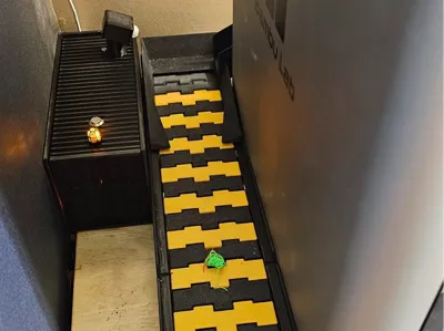
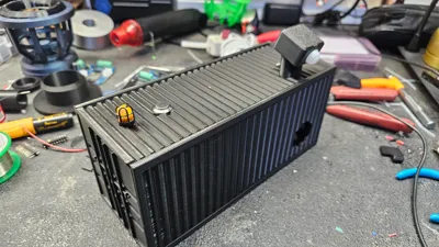
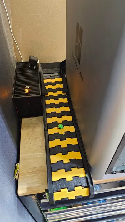
This mod is just a container for a motor and controller to somewhat automate the conveyor.
After a few failed prints due to my chute backfilling I started searching out conveyor belt options. Tried making my own but ultimately came across Nigels A1 poop conveyor which looked like it would work perfect. I wanted it to be automated and standalone so i decided to use an ESP32 relay board and an IR sensor to trigger when a poop came down the chute.
I did not design anything for this except the holder for the IR sensor. Everything else was files I found on MakerWorld then modified. All credit for original files goes to their respective creators. The mods to the container are pretty sloppy as I'm not a designer and have been drunkely working on this randomly for like 6 months I have uploaded a 3mf of the files I modded, and a zip file of that includes the modded files, source files, obj file and the code for the esp32.
The conveyor belt: (I used the extension piece as well)
https://makerworld.com/en/models/148083?from=search#profileId-161573
The container:
https://makerworld.com/en/models/379848?from=search#profileId-279994
Chute:
https://makerworld.com/en/models/18221#profileId-34436
For the electronics i used this controller.
https://www.aliexpress.us/item/3256805413009927.html?spm=a2g0o.order_list.order_list_main.78.73081802ZQ1XSp&gatewayAdapt=glo2usa
This for the motor.
https://www.amazon.com/gp/product/B099K6RW48/ref=ppx_yo_dt_b_search_asin_title?ie=UTF8&th=1
Strobe light was just for kicks. oh wait. for safety!! lol
https://www.aliexpress.us/item/3256805697800101.html?spm=a2g0o.order_list.order_list_main.48.73081802ZQ1XSp&gatewayAdapt=glo2usa
PIR Sensors
https://www.amazon.com/gp/product/B07RT7MK7C/ref=ppx_yo_dt_b_search_asin_title?ie=UTF8&psc=1
Then just powered it with a 12v dc plug. The push button and terminal blocks and other misc electrical bits are from Amazon. Used ChatGPT 4o to write the code.

Comment & Rating (26)