
30:1 Harmonic Gearbox with 520 DC Motor and 6mm D-Shaft
Print Profile(1)

Bill of Materials
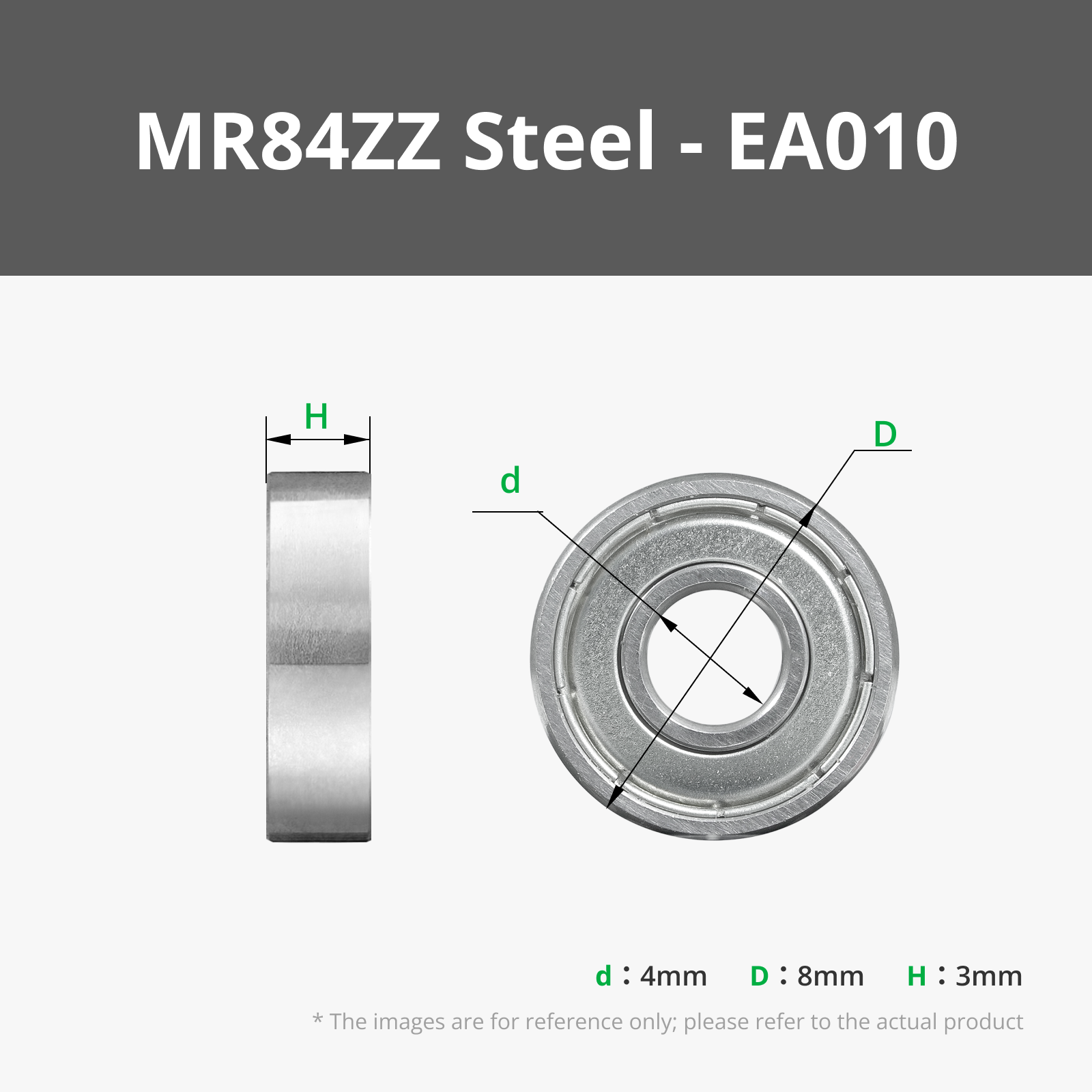


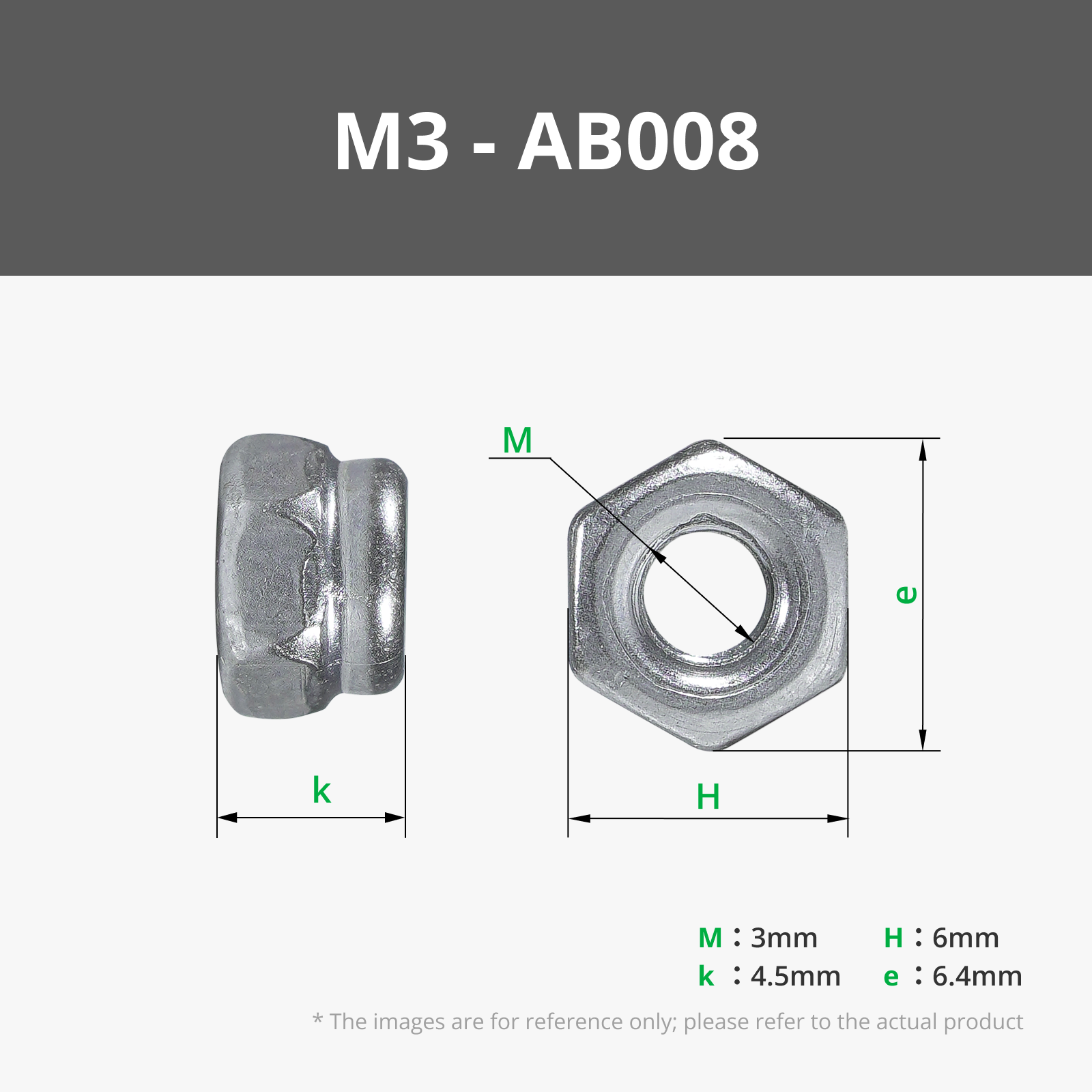

- 520 High Torque Micro Brush DC Motor x 1: https://www.amazon.com/dp/B09Q5SWVKB/ref=dp_iou_view_item?ie=UTF8
- 6807-2RS Deep Groove Ball Bearing 35mm x 47mm x 7mm x 1: https://www.amazon.com/dp/B0D53YNRRW
- 6701-2RS Deep Groove Ball Bearing 12mm x 18mm x 4mm x 1: https://www.amazon.com/dp/B082PQ8DC2
- M3-0.5 x 35mm Socket Head Cap Screws x 4: Option 1: (1 pack needed) M3 Assorted Screws: https://www.amazon.com/dp/B0BMQFHDBH?ref_=ppx_hzsearch_conn_dt_b_fed_asin_title_3
- M3-0.5 x 35mm Socket Head Cap Screws x 4: Option 2: (1 pack needed) https://www.amazon.com/iExcell-Socket-Screws-Bolts-Finish/dp/B08B1TK641/ref=sr_1_6?sr=8-6
Description
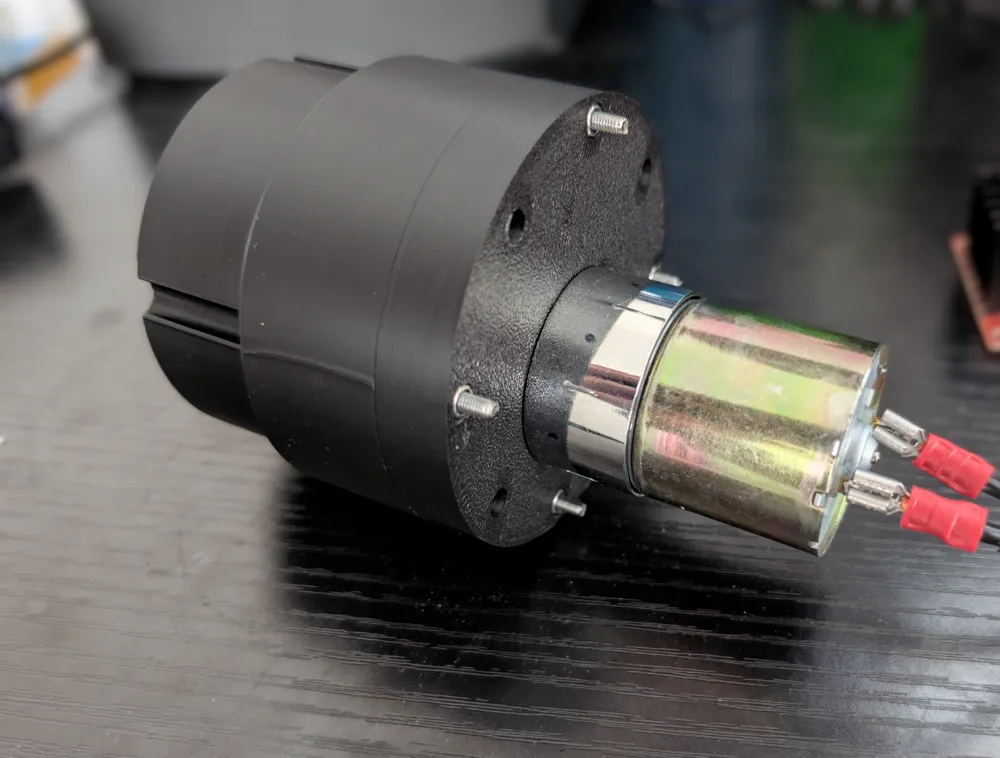
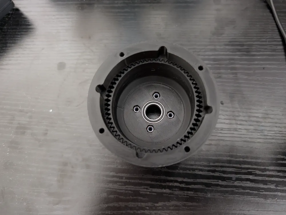
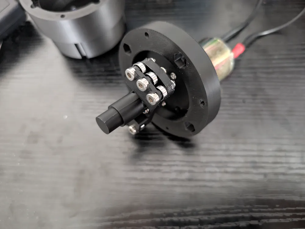
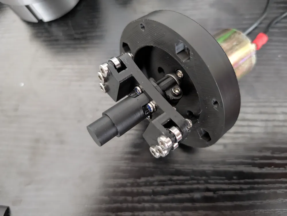

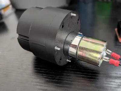
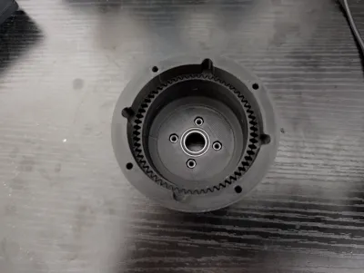
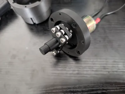
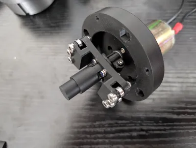
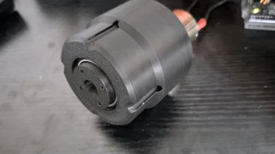
A 30 to 1 harmonic drive gearbox. I designed this gearbox to provide high torque and negligible backlash for a robotic arm I am developing. I may update this design or provide other variants as I continue this project. As of writing this description, I have only printed this gearbox for a 520 DC motor from Amazon (linked in the bill of materials), but I have a design made for a NEMA 23 stepper motor that I plan to upload in the future.
Since my robotic arm is in early development, I haven't been able to properly test the performance with the motor to provide torque specs. However, since the flex spline is printed vertically, the limiting factor is likely to be the layer adhesion rather than the motor torque. For this reason, using materials with better layer adhesion will allow for higher torque limits.
Furthermore, using strong but flexible materials for the flex spline would be beneficial. Materials like PETG, nylon, or ASA (CF variants preferred for strength) allow for more flex than PLA and less force resisting the rotation of the wave generator. This results in higher torque output.
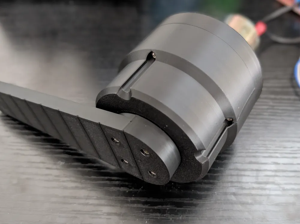
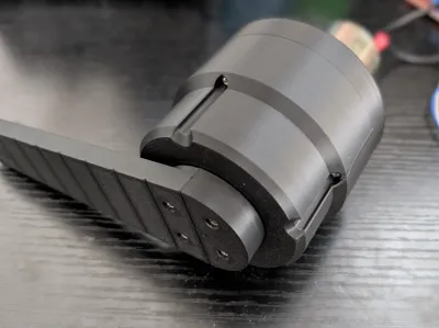
As a final note, I included an arm in the print file to use for testing. There are two lobes at the end which are 0.125m from the center of rotation. Attaching the gearbox/motor to a fixed structure and placing a simple kitchen scale beneath the lobes will allow you to approximate the output torque. If the scale is set to grams, and the arm is horizontal when the pressure is applied, you can multiply the reading by
0.0012 N*m/g to find the output torque in N*m.
The step files for the 3D-printed parts are available under the raw model files. Additional information, files, and an assembly guide are available on my github:
https://github.com/bjhling/30-1-Harmonic-Gearbox/tree/main
I hope this gearbox can be of help to you, feedback and suggestions are appreciated.
License

You shall not share, sub-license, sell, rent, host, transfer, or distribute in any way the digital or 3D printed versions of this object, nor any other derivative work of this object in its digital or physical format (including - but not limited to - remixes of this object, and hosting on other digital platforms). The objects may not be used without permission in any way whatsoever in which you charge money, or collect fees.


Comment & Rating (4)