
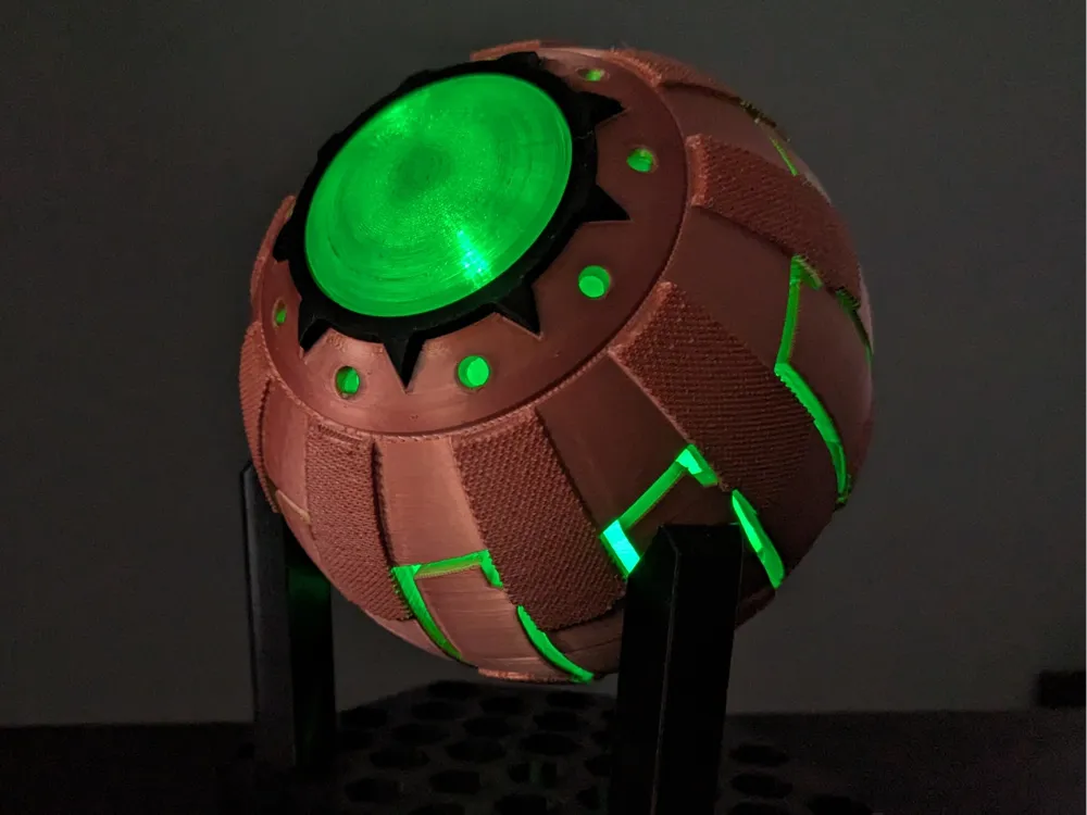
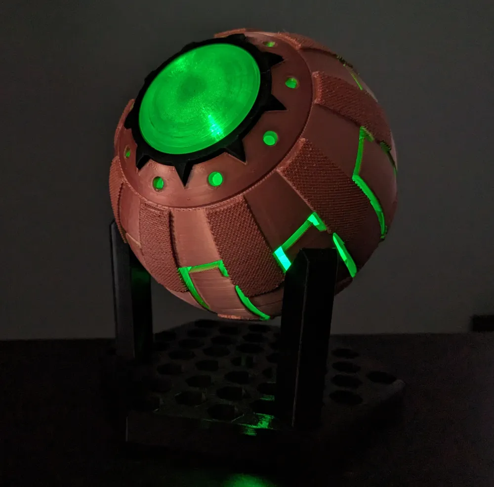
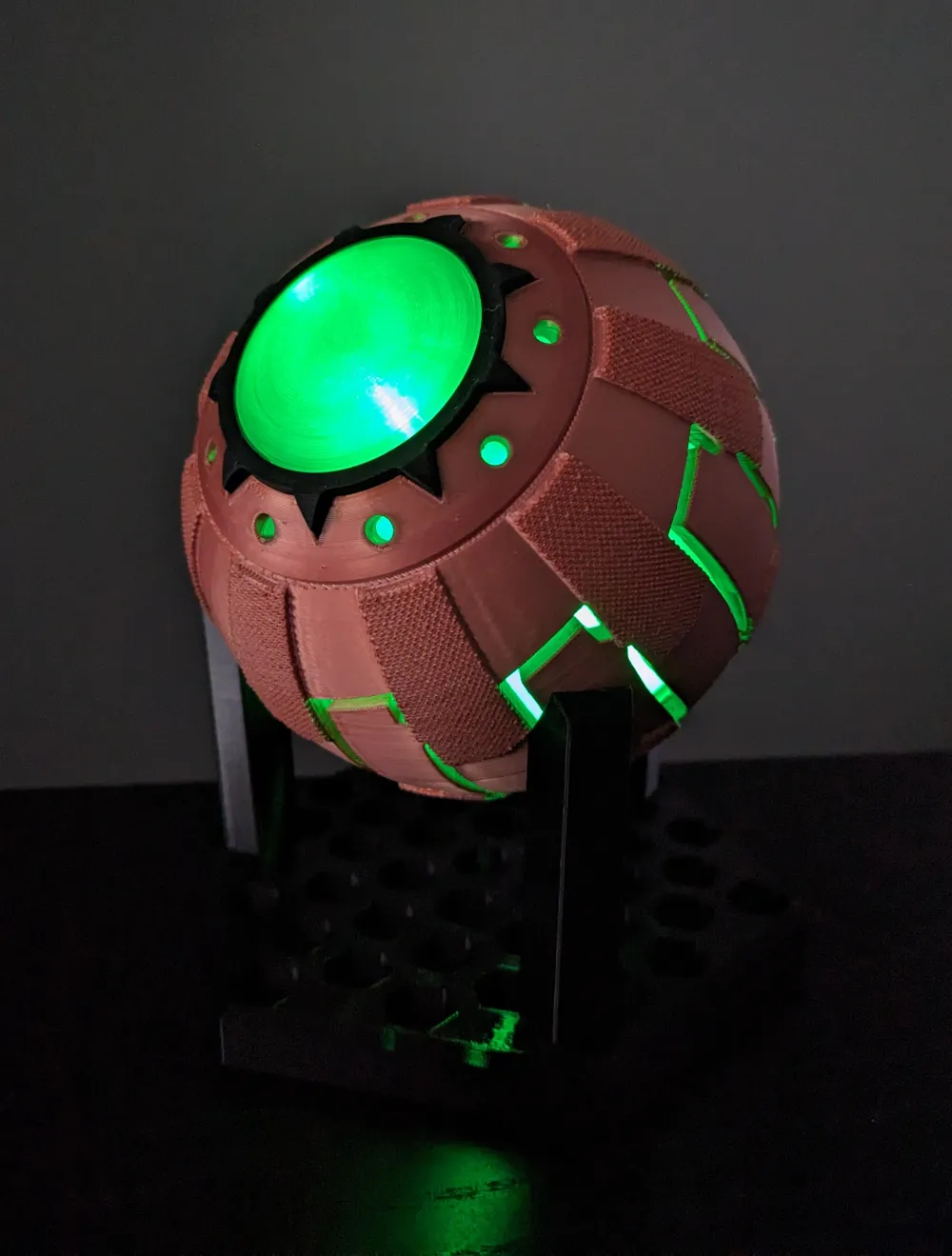
Green Goblin Pumpkin Bombs



Print Profile(3)


Bill of Materials


Description
I'm something of a 3d printer myself.
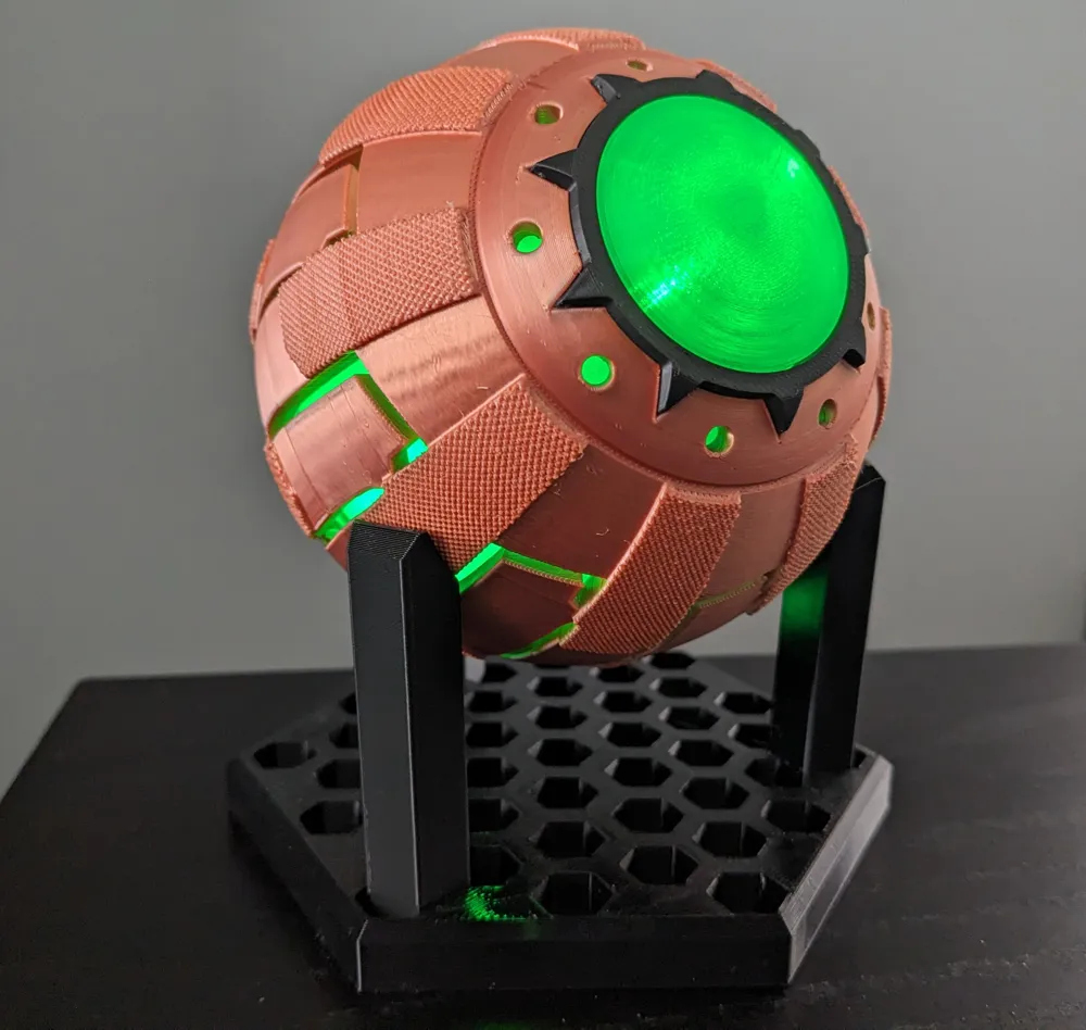
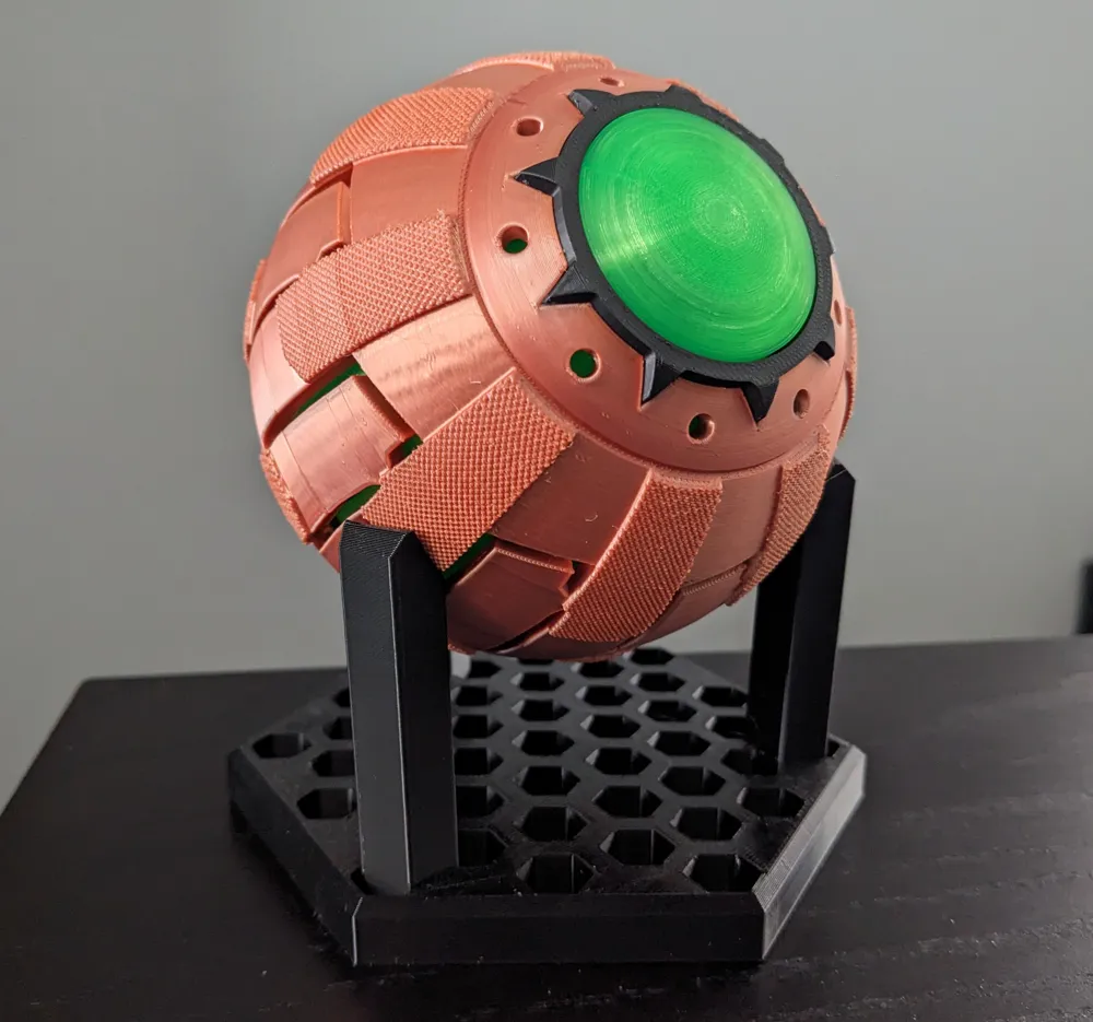
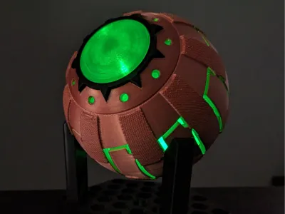
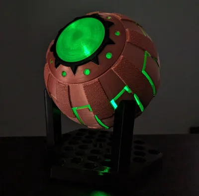
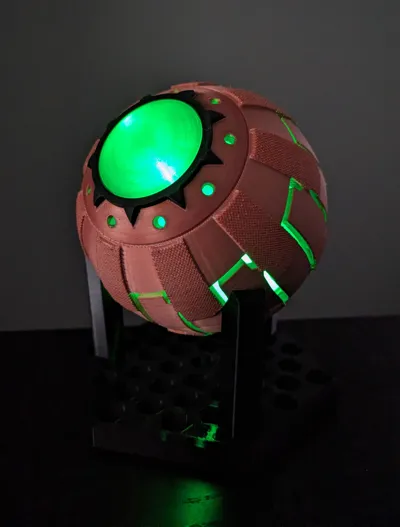
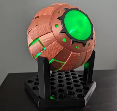
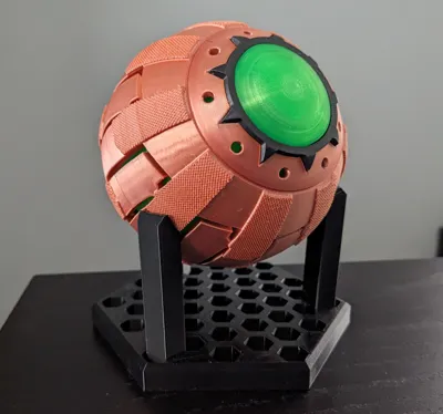
Do you hate spiders? Do you like cool tech? Do you like things that glow? Try Oscorp's newest spider deterrent technology; the pumpkin bomb.
I designed these myself using fusion and they have been designed in a way to be able to both light up and actuate like the real thing. All that is needed is a couple of small maker supply parts, which will be listed below. These are a complete revamp of my previous design that has been posted to printables and thingyverse. Ultimately, I think these are vast improvement over the original.
Print Profiles and Personal Preferences
- My print profile contains all parts that are needed to be printed
- The main print profile is set up for a core XY printer and the parts are optimized for that type of printer. I did print some test pieces on my A1 mini, and the profile tends to work on this with no trouble as well; all parts will fit on all bambu printers
- however the small connector pieces may need brims on bed-slinger style printers
- The print profile is set up to print in PLA
- My outer portion is printed in silk-pla (color: red-copper) and the inner portion is printed in translucent green pla
- For translucent and silk pla, the hotter the temperature, the more clear or the more shiny the filament will be after printing. I found for both 220C was my sweet spot
- This may differ for you filament and to get a more shiny or more translucent color try increasing the temperature 5-10 degrees
- For translucent and silk pla, the hotter the temperature, the more clear or the more shiny the filament will be after printing. I found for both 220C was my sweet spot
- The top and bottom rings were printed in black pla+
- These two pieces are different--as the bottom has a smaller inner diameter to prevent the bottom screw from being to pass all the way though, please note this and see the assembly guide below for more information
- My outer portion is printed in silk-pla (color: red-copper) and the inner portion is printed in translucent green pla
- The print profile is set up in a way to print most of the pieces on a separate plate. While parts that are the same color can be printed on the the same plate, the best surface texture and appearance will be given when pieces are printed alone
- silk and translucent filament both tend to dull or become hazy when multiple pieces are printed at the same time
- On the plate with the bottom screw, there are three sets of connectors (one set [6 connectors] are required for assembly).
- Each of these sets of connectors are slightly different sizes and depending on your filament and flow you may need a larger or smaller size to fit in the slots
- Together, they add very little extra filament to the print, so the best thing is to print all the connectors and choose which set/sets work best
- In the event that someone has connectors that do not end up fitting, let me know and I can try to add more sizes
- alternatively you can use the slicer to increase just the x or y dimension a few tenths of a mm
- do not increase the z dimension scale
- Each of these sets of connectors are slightly different sizes and depending on your filament and flow you may need a larger or smaller size to fit in the slots
Assembly Instructions
- After all parts are printed carefully remove the tree supports
- use flush cutters to remove the small supports
- the most tricky ones are going to be the small 90 degree overhangs, but they should pop out with something relatively thin
- I recommend dry fitting all parts together before gluing
- before dry fitting, test the light to ensure the magnet activates the light
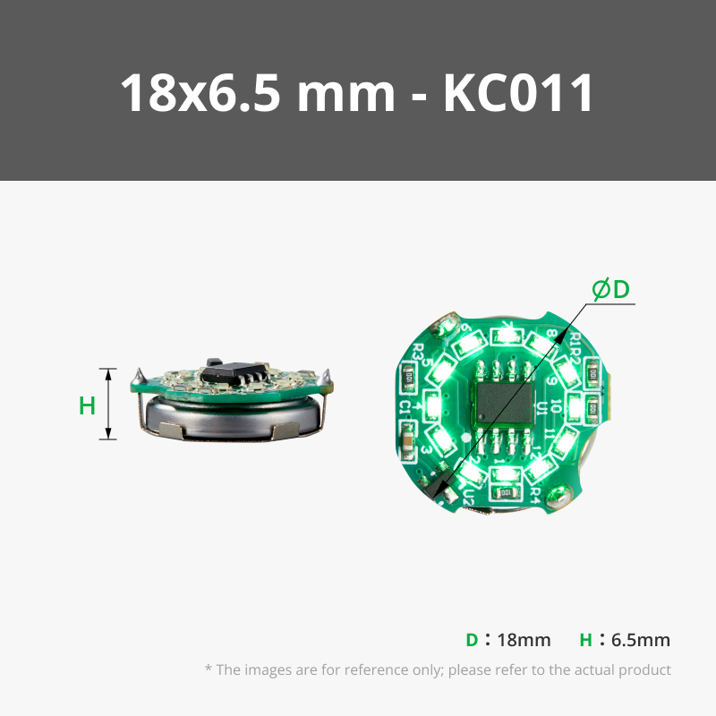
- Take the Ring LED magnetic control switch and place it lights side up into the top of the bottom screw
- the bottom screw contains two very small notches that align with the small extensions on the sides of the LED
- the light should be able to be depressed easily as long as the angle is straight down
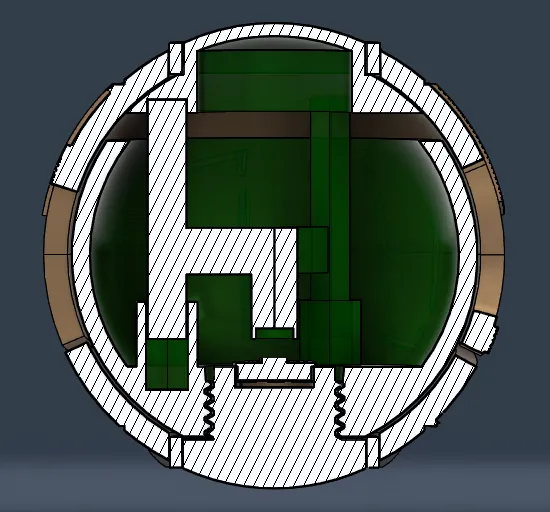
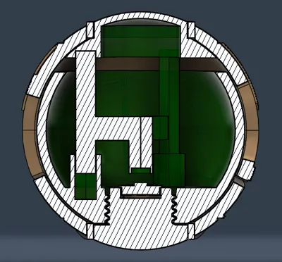
- The longest prongs on the plunger are going to fit into the holes of the top inner ball
- add a small amount of CA glue to the holes and press the prongs into place and let this dry
- Once dry, add a small amount of CA glue to the bottom center post hole and place the 8mm LED that comes with the ring LED into this hole
- I found that orientation didn't seem to matter, as the light is activated by either pole--double check your own LED though
- The top and bottom rings can then be attached to the top and bottom of the outer shells
- The outer shell models are labeled top and bottom in the print, but, for the purpose of assembly, switching them won't have any negative effects
- attach these by placing a small amount of CA glue into each of the cutouts on the shell. Spreading a thin layer of CA glue around the inner diameter sections will also help this to adhere
- press the rings into place for several seconds and let these dry
- Place the 0.5x7x12 mm compression springs into the three holes of the bottom inner ball--no glue is necessary here
- Place the ball into the bottom outer shell (this is important; the bottom shell becomes the one where the bottom ring was placed. The bottom ring can be differentiated by the small lip on the inner diameter to prevent the bottom screw from moving past a certain distance)
- Using the bottom screw that has the LED already placed, screw this into the bottom of the inner ball
- this next step is crucial for the ability to take this thread out at a later time (like in case the LED dies or the battery has to be replaced)
- when threading do not thread too tightly as this will make removing the screw later impossible
- thread the screw using the inner ball until it is just finger tight and to where it doesn't unscrew on its own
- Place the plunger assembly lower prongs into the holes of the lower inner ball and test the spring mechanism
- test to make sure that the springs do not bind and that moving the magnetic up and down works the LED
- the LED has four settings before it will turn off
- make sure it stays off on the last one when the magnetic is in the up position
- if for some reason it doesn't you may need to pull the compression springs apart to make them slightly longer
- Finally, place the connectors into the connector slots and then press the two outer shells together
- make sure to align the top and bottom pieces correctly
- the patterning should alternate so that if the top face has texturing then the face on the bottom part directly below it should be smooth. Do not put it so that the both the top and bottom surfaces above and below each other are both textured or both smooth
- if the connectors are tight enough, no glue will be necessary
- however very small amounts of CA glue can be used to make this connection more permanent
- dry fit the connectors before putting anything together so you know which ones to use
- actuate the top dome to cycle the LED settings and make sure the LED remains powered off after the last setting
- in my experience any looseness between the top and bottom outer shells will allow the springs to rattle and may allow for the LED to be activated by just moving the ball or shaking it
- I used the tightest fitting connectors I could comfortably get into the slots and did not end up gluing the halves together
- if everything is assembled correctly, the top part and bottom part should both be under tension and nothing should rattle inside and the LED should remain off unless the top is depressed
- make sure to align the top and bottom pieces correctly
- To replace the LED or battery, you can gently pry apart the outer shells (not recommended if properly fit) or you can depress the top dome into so that it touches the lower then dome and hold it in place while then using the pads of your fingers to unscrew the bottom screw
- if this was screwed too tightly, this may not work, so it is imperative that you test this before snapping or gluing the outer shells together
- it took some practice before I could hold everything in place in order to do this--the green inner ball is not secured so it can freely spin
- pushing the top dome down will push the bottom into the black ring, which should make it less prone to spinning--which will allow the bottom screw to unscrew
License

You shall not share, sub-license, sell, rent, host, transfer, or distribute in any way the digital or 3D printed versions of this object, nor any other derivative work of this object in its digital or physical format (including - but not limited to - remixes of this object, and hosting on other digital platforms). The objects may not be used without permission in any way whatsoever in which you charge money, or collect fees.


Comment & Rating (80)