
ESP8266 NodeMCU Case - Customize or ready print
Print Profile(6)


Description
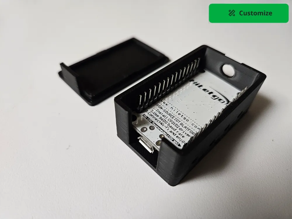
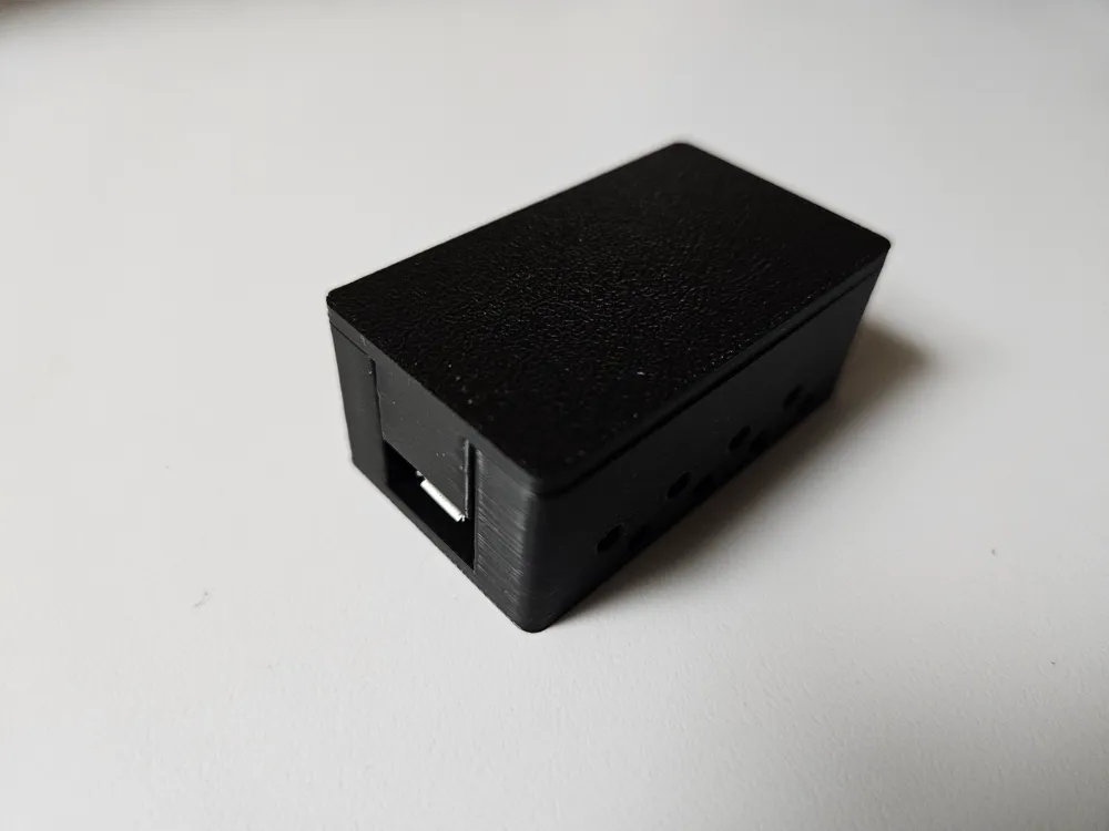
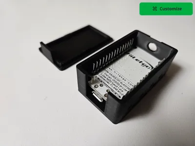
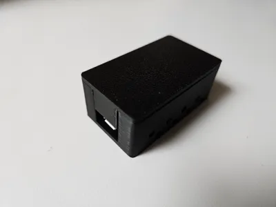
ESP8266 NodeMCU Case - Customizable (or ready to print)
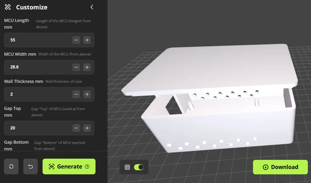
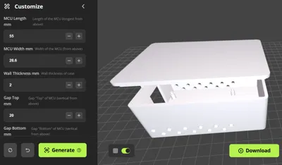
Select Customize to make your very own case
OR
Select one of the “Ready To Print” profile options
When customizing, the parameters are not validated. Use values that make sense and fully preview the model in Bambu Studio before printing. Here are some tips / suggestions:
- The parameter descriptions are based on the MCU being vertical and viewed pins up from above
- The MCU dimentions default to what I have tested. Adjust carefully
- Be extra careful adjusting the radius of the supports - The MCU clicks tightly in to these supports pins up
- The “Gap” parameters refer to having extra room around the MCU for sensors and stuff - I suggest 1 mm minimum each
- I suggest a minimum of 1 mm for lid thickness (like for a presence sensor) - 2 mm best
- Walls are best at 2 mm
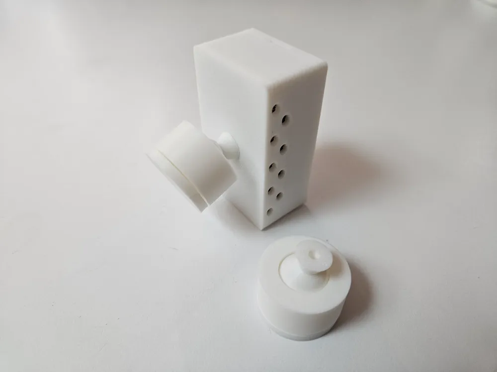
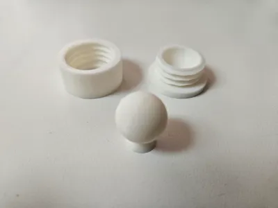
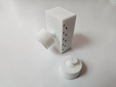
- A mounting screw hole can optionally allow for a wall mount ball joint
- If you don't want a screw hole use like 0.01 mm for these parameters
- A round cutout at the top can be enabled by making it bigger than the 0.01 mm default
- If you make the top cutout bigger than maybe 8 mm, enable support
- Preview the customized download before printing
- Prease comment or message me on how the Customize worked for you so that I can improve if needed
After you download your custom case, you need to :
- Select it (click it)
- Click "Split to Objects"
- Click "Arrange all objects"
- Click "Auto Orient" (lid should now be top / flat side down)
- Use a standard 0.2 mm layer preset. I personally like one wall on first layer
Also see:
Note:
- A 20 mm option fits the chip with the header pins but has no room for anything else
- A 20 mm option should work well if you solder directly to the PCB
- A 35 mm option adds lots of room for jumper wires
- Delete the Cable Cutout “negative part” from the Objects view if not needed (ready to print)
- Delete the Screw Hole “negative part” from the Objects view if not needed (ready to print)
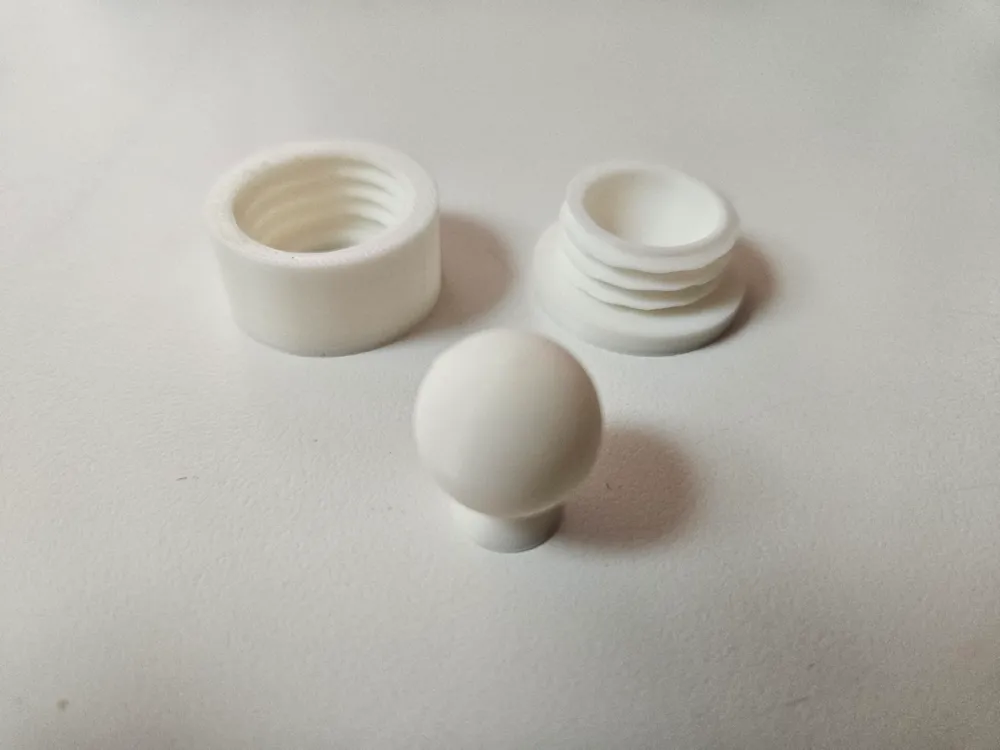
- The Screw Hole can be used with the Basic Ball Joint for an adjustable wall mount
- The case is designed to have a tight snap fit for the microcontroller
- "Top Support" options are available if the chip is not a tight fit (ready to print options)
- Please let me know how yours fit or if you need help
I have over 250 different box size and type variations.
Checkout All My Boxes to decide the best type for your needs.
Also checkout:
Boost Me (for free)
Please support my designs so that I can share even more with the community.
License

You shall not share, sub-license, sell, rent, host, transfer, or distribute in any way the digital or 3D printed versions of this object, nor any other derivative work of this object in its digital or physical format (including - but not limited to - remixes of this object, and hosting on other digital platforms). The objects may not be used without permission in any way whatsoever in which you charge money, or collect fees.


Comment & Rating (18)