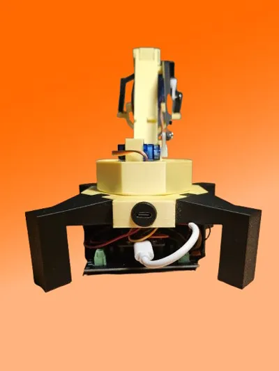
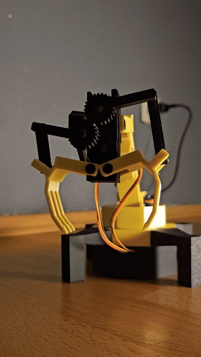
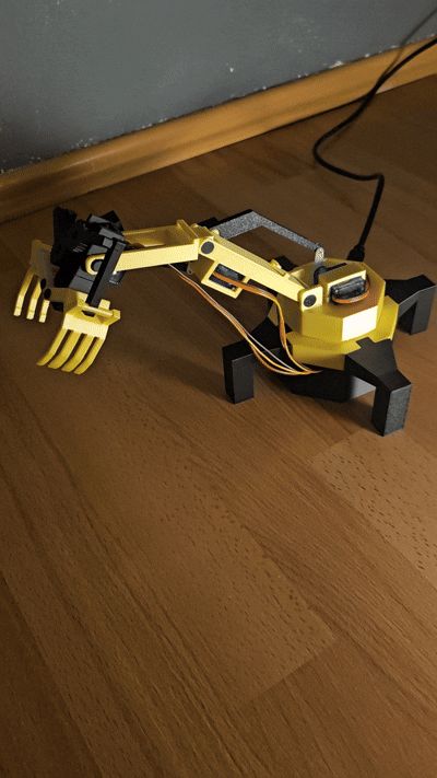
PS4 Controller-operated Robotic Gripper Arm


Print Profile(1)

Bill of Materials

Description
A PS4 Controller-controlled robotic gripper arm, powered by 4 servo motors and an ESP.
- Rotating base
- Two articulated arms
- Functional gripper
Bill of Materials:
4x SG90 Servo Motor
1x ESP32
1x ESP32 module holder for screw terminals (optional)
1x USB cable (I use a USB-C connector here)
Jumper wires
Assembly requires some caution, as some parts, especially the ball joints, may be fragile.
Wiring:
ESP32:
- GPIO 22 ---> Signal Servo 1 (Base)
- GPIO 23 ---> Signal Servo 2 (Arm 1)
- GPIO 5 ---> Signal Servo 3 (Arm 2)
- GPIO 18 ---> Signal Servo 4 (Gripper)
- Servos:
- Each servo has 3 wires:
- Signal (orange): Connects to the corresponding ESP32 GPIO.
- VCC (red): Connects to the external 5V power supply.
- GND (black): Common ground connection (ESP32 and servos).
- Each servo has 3 wires:
- ESP32:
- Connect the GPIO pins (22, 23, 5, 18) to the signal pins of the servos.
- Connect the GND of the ESP32 to the servo GND line.
Connect all red servo wires together with the (+) line for the ESP and power supply.
Connect all black servo wires to the (GND) line of the ESP and power supply.
If the ESP pins are used as described, the attached sketch can be used.
An excellent video on setting up the ESP to connect to the PS4 controller can be found here:
https://www.youtube.com/watch?v=EEViXFoSzww
Then connect the power supply, upload the sketch, done!
Put the controller into pairing mode using the PS button and the share button. It should then connect automatically, and the servos can be controlled. I recommend testing the servos individually before attaching the mounts to check the start and end angles. Also, before uploading the sketch for the first time, I recommend loosening the motor mounts, as they will first move to a starting position.
Good luck with the build. I would appreciate seeing some pictures.
Documentation (1)
License
You shall not share, sub-license, sell, rent, host, transfer, or distribute in any way the digital or 3D printed versions of this object, nor any other derivative work of this object in its digital or physical format (including - but not limited to - remixes of this object, and hosting on other digital platforms). The objects may not be used without permission in any way whatsoever in which you charge money, or collect fees.
Comment & Rating (5)