Daily Routine Panel


Print Profile(1)

Description
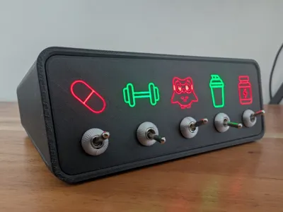
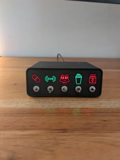
Daily Routine Panel
This is a 3D-printed desk device designed to track daily habits using illuminated icons and toggle switches. Each icon is engraved on the front plate and backlit with RGB LEDs, creating a clean and satisfying physical tracker for daily routines.
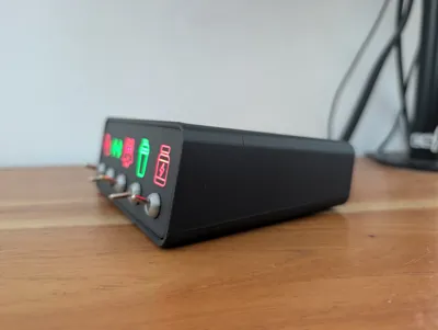
The enclosure assembles without supports and includes proper cutouts for toggle switches, LEDs, and internal wiring mounted on a breadboard.
🔌 Electronics Used
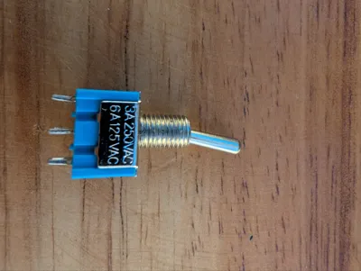
Toggle Switches
Micro Lever Inverter Switch ON/OFF (3A)
- 2-pin, single-channel
- Silver contacts
- Solid and clicky feel
- Used to switch the LEDs on and off
LEDs
5mm RGB LEDs – Common Anode (4-pin)
- High brightness
- Colors used: Red + Green (one per icon)
- 3V forward voltage per LED channel
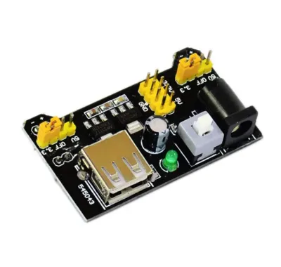
Power Module
MB102 Breadboard Power Supply (5V / 3.3V)
- Powered via USB
- Provides stable 5V for LEDs and switches
Breadboard
400-point breadboard
- Used for wiring without soldering
Jumper Wires
Standard male–male jumper wires
- Used to connect switches, LEDs, power rails, and resistors
Resistors
You typically use 220 Ω resistors for 5mm RGB LEDs at 5V.
These limit the current so the LED doesn’t burn out.
🔧 Additional Hardware
🔩 Screws
To assemble the enclosure you will need:
4× M3 × 6 mm hex-cap screws (M3x6 HC)
These hold the front panel tightly to the main body.
🔧 How the Wiring Works
The circuit is extremely simple and beginner-friendly:
1. Common Ground
- All toggle switches share the same GND line.
- The center pin of each switch connects to GND using a jumper wire.
2. LED Color Control via Switch
Each RGB LED has 3 color pins: Red, Green, Blue (you use Red + Green for this project).
- The outer pins of the switch connect to
- Red LED pin
- Green LED pin
When you flip the switch, it completes the circuit and lights that color.
3. LED Power (Common Anode)
- RGB LEDs have one long pin (the anode = +).
- This long pin connects to 5V through a 220 Ω resistor.
So the chain is:
5V → 220Ω resistor → Long LED pin (anode) GND → toggle switch (center pin) Switch outer pins → Red & Green LED pins
When the switch is ON:
GND flows to one of the LED color pins → LED turns on.
4. Power Module
- The MB102 module powers everything at 5V
- Breadboard rails are used for 5V and GND distribution
- All LEDs share the same voltage rail / resistor configuration
🧩 Extra Notes
- Only one resistor is needed per LED (on the anode).
- You can swap the colors (R/G) by changing which pin of the LED you connect to the switch.
Comment & Rating (7)