Customizable Display Box


Print Profile(2)

Description
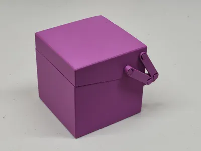
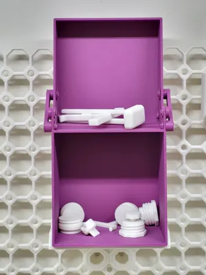
This customizable 3D model is a box with a hinged lid that opens to create a vertical display case for small items or lays flat to form a work tray.
Assembly
There is some assembly required. The model includes all the parts as printable objects.

Step 1: Identify the pieces printed on the third plate. Note that the model includes 2 extra lock clips, in case they break or get lost.

Step 2: Insert the short pins into the ends of the flat bars, and insert the long pins into the ends of the raised bars. The print should have enough tolerance for them to fit without much force. They can be sanded or trimmed with a knife if they are too wide.

Step 3: Insert the pin on one end of the flat bar into the hole in the lower corner of the lid as shown. Slide on a lock clip to hold the pin in place. The bar should rotate freely. Repeat on the other corner of the lid with the other flat bar.

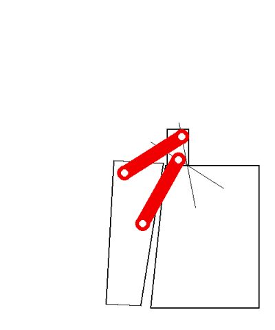
Step 4: Insert the pin on one end of the raised bar into the innermost hole on the hinge tab on the box as shown. Note that the bar should be on the outside of the model. Slide on a lock clip to hold the pin in place. The bar should rotate freely. Repeat on the other hinge tab with the other raised bar.

Step 5: Rotate the raised bars out of the way as shown. Slide the lid next to the box. Fit the pins on the flat bar into the remaining hole on the box hinge. Add the lock clip and repeat on the other side.

Step 6: Rotate the raised bar across the flat bar and insert the pin in the remaining hole on the lid. Add a lock clip and repeat on the other side to finish the connection.


Optional hardware connection
The bars can be connected with screws and lock nuts instead of the plastic pins and lock clips. The holes will fit M4 screws with countersunk heads nicely, although the lock nuts do stick out a bit further than the ends of the clips. You will need 8 lock nuts, 4 screws around 10mm long, and 4 screws 12-14mm long. Or longer if you customize the model with thicker walls.
Customizing
There is an OpenSCAD script for this model that can be used to generate boxes ranging from 75mm - 200mm in each direction. Just click on the Customize button listed under the print profiles and adjust the box to the size that you want. When finished, save the model 3MF file and open it with Bambu Studio. There will be 3 plates. Plate 1 is the box with the hinge tabs and holes correctly positioned. Plate 2 is the lid with the holes correctly positioned. Plate 3 is the connecting pieces.
Printing Custom Models
The box hinge tabs need to have supports added to print cleanly. The generated model should have manual supports turn on, but you will still need to paint in the support locations by hand before printing.

Select the box on plate 1 and click the icon to start Support Painting.

Check the box for “On overhangs only”. Set the highlight slider to about 35-40. Rotate the box so you are looking at the underside of the hinge tabs. Use the left mouse to paint in the crosshatched areas under the tabs.

When finished, switch to the Preview tab to confirm that you have one tree supporting each hinge tab.
I suggest also turning on Brim Ears for both the box and the lid. That should help prevent the corners of the box and lid from curling up during the print. Select the box, click Brim Ears (E). Check Auto-generate points, and click the link to enable the brim painting setting. Repeat for the lid.
You may be able to arrange all of the pieces on a single plate depending on the size of your box. If you do, be careful about using the Auto-Arrange option in Studio. It may try to print the pins upright. They are designed to print horizontally so the layer lines are down the length of the pins and not across them.
Credits
Are you still reading after all of that? Thank you! This project was inspired by a video from maker Laura Kampf about her toolboxes that use this hinge design. I set about learning the maths that were involved and made a couple prototypes in Fusion 360. I wrote and fiddled a bit with a python model and transferred it all into openscad to make the customizable model presented here.
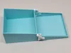
The tray used in the photo showing the cube box on my multiboard wall was generated using the Multiconnect Part Generator by BlackjackDuck.
Comment & Rating (0)