
Tapo C120 camera mount for A1 (+ disassembly)

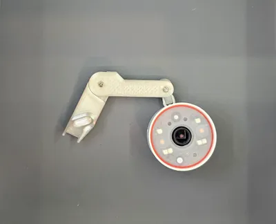
Print Profile(1)

Description
This is an A1 compatible version of the camera mount I made for A1 mini (LINK), I don't have the full size A1 yet, but a user from MakerWorld tested the fit and it's fully compatible. Will upload more pictures when I finally get the new printer.
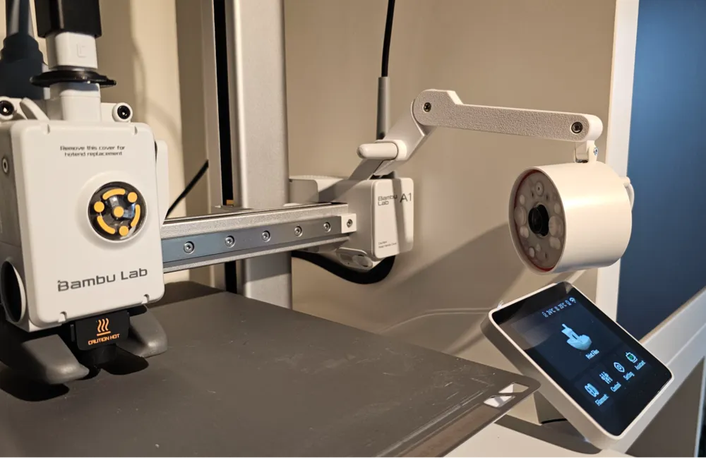
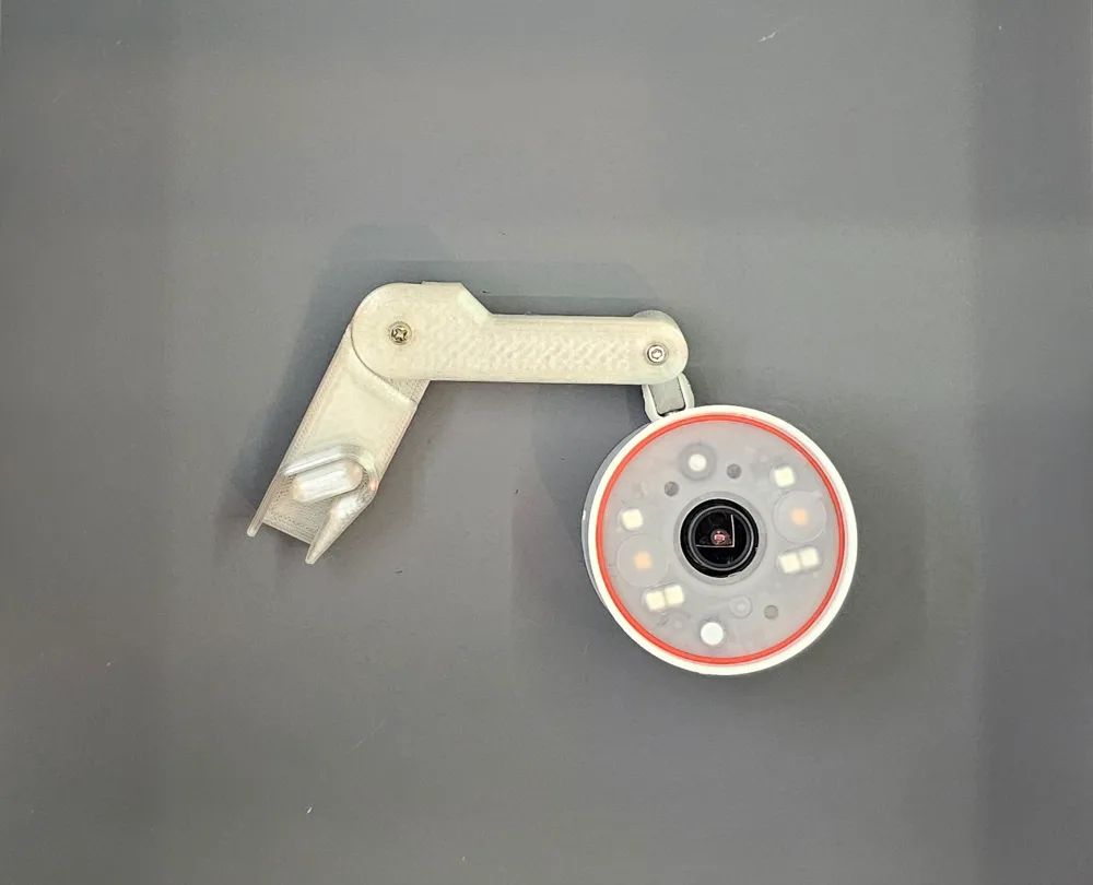
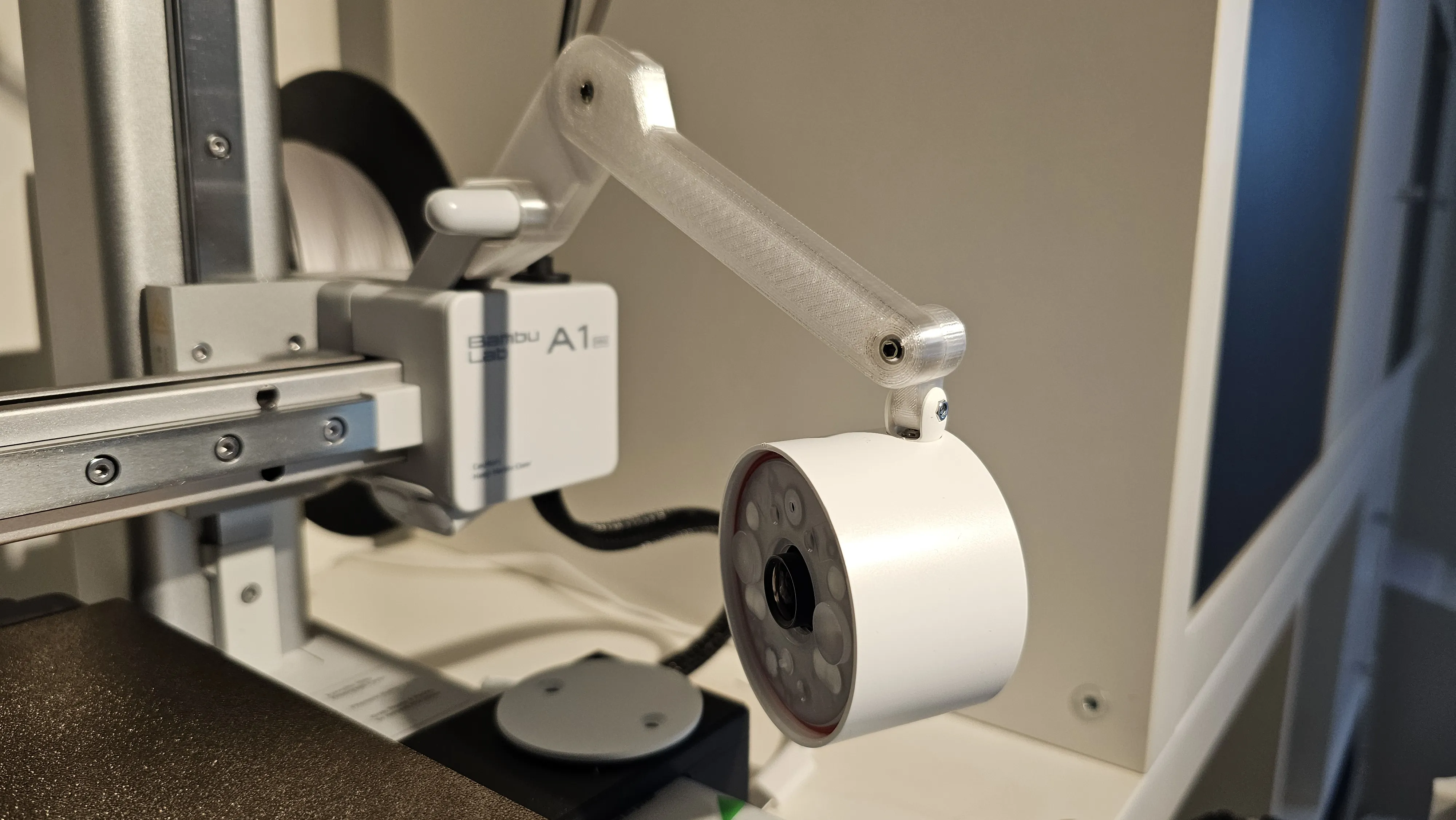
Tapo C120 camera mount for A1, with pivoting arm for adjusting the angle to desired position. There are also a long and medium versions included for more view customisation.
Very durable and prints without any supports.
Note: there are 2 versions of the ‘connector’ between c120 camera and the arm, ‘camera connector.stl’ is compatible when using with stock ‘extension arm’ (see pictures 1 & 2), the ‘camera connector 2.stl’ is when you wish to mount the camera directly to the arm (see picture 3).
Hardware required:
- 2x M3 nut
- 1x M3 6mm screw
- 1x M3 20mm screw
Note: after you find the right position it is highly recommended to use loctite on the screws as the significant vibrations taking place during prints might loosen them over time.
Boost Me (for free)
Please boost me if you like the design, it really means a lot!
Adjusting camera focus
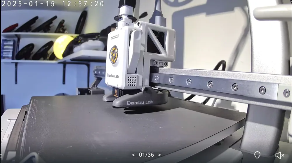
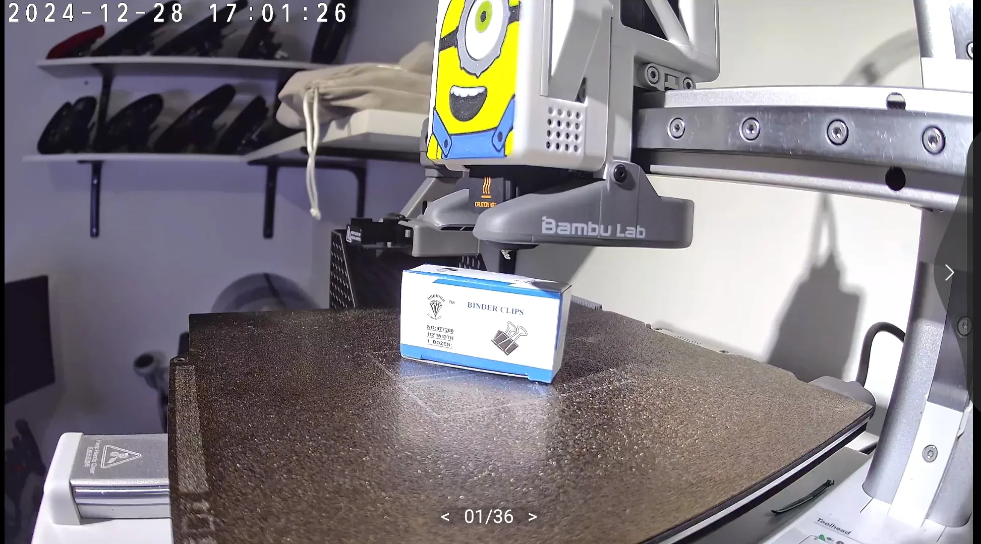
By default tapo cameras have a fairly long focus, which makes it pretty bad when used for monitoring a 3d printer, but with a fairly simple modification you can adjust the focus and get a super sharp picture, like the example below:
Tools you'll need:
- prying tool kit (e.g. THIS)
- crafting knife
- (optional) small heat-gun or hairdryer
Here are the steps:
- unplug the camera from power
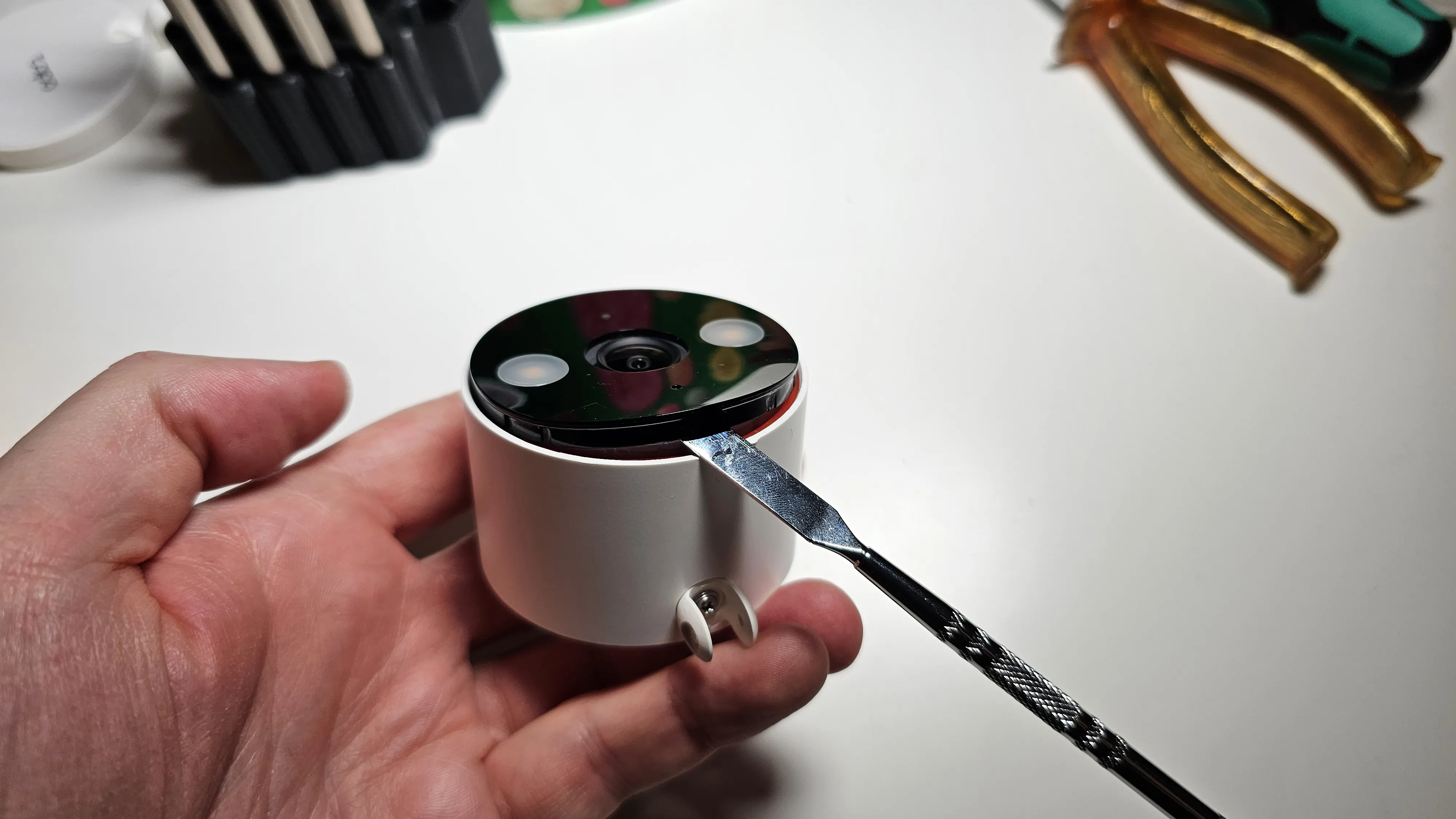
remove the front black plastic cover with the pry tool, recommend using stiff metal one, slide it underneath the black front cover and push upwards, whole internal camera assembly should come out
be careful when removing the internals of the camera as there's a cable connecting the speaker, gently disconnect it from pcb
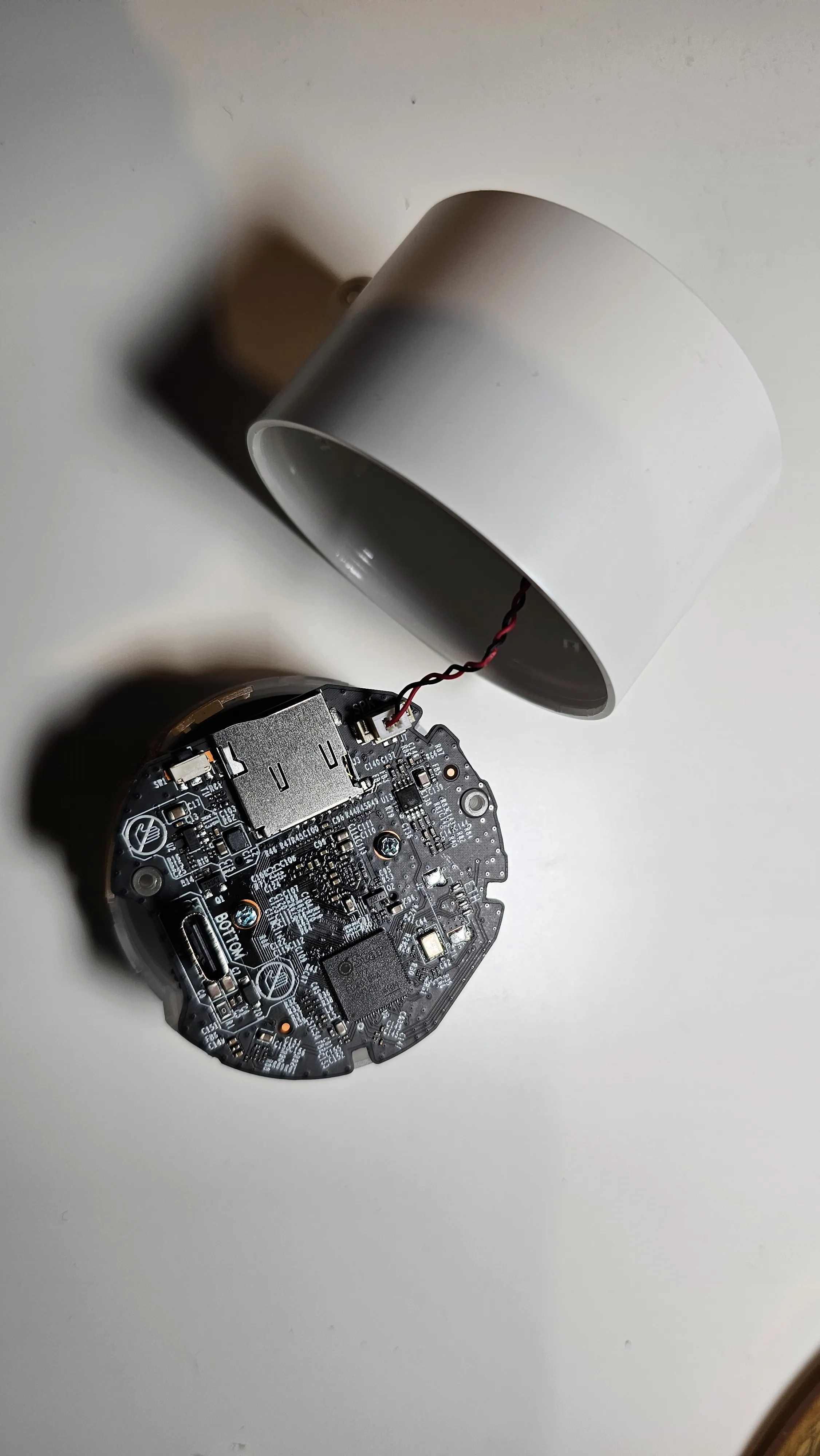
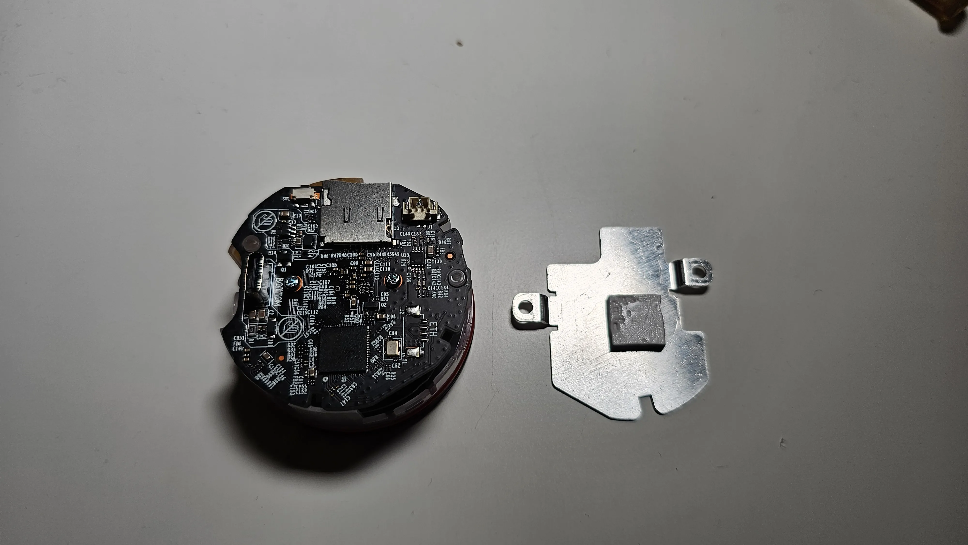
remove the back heatshield from the pcb
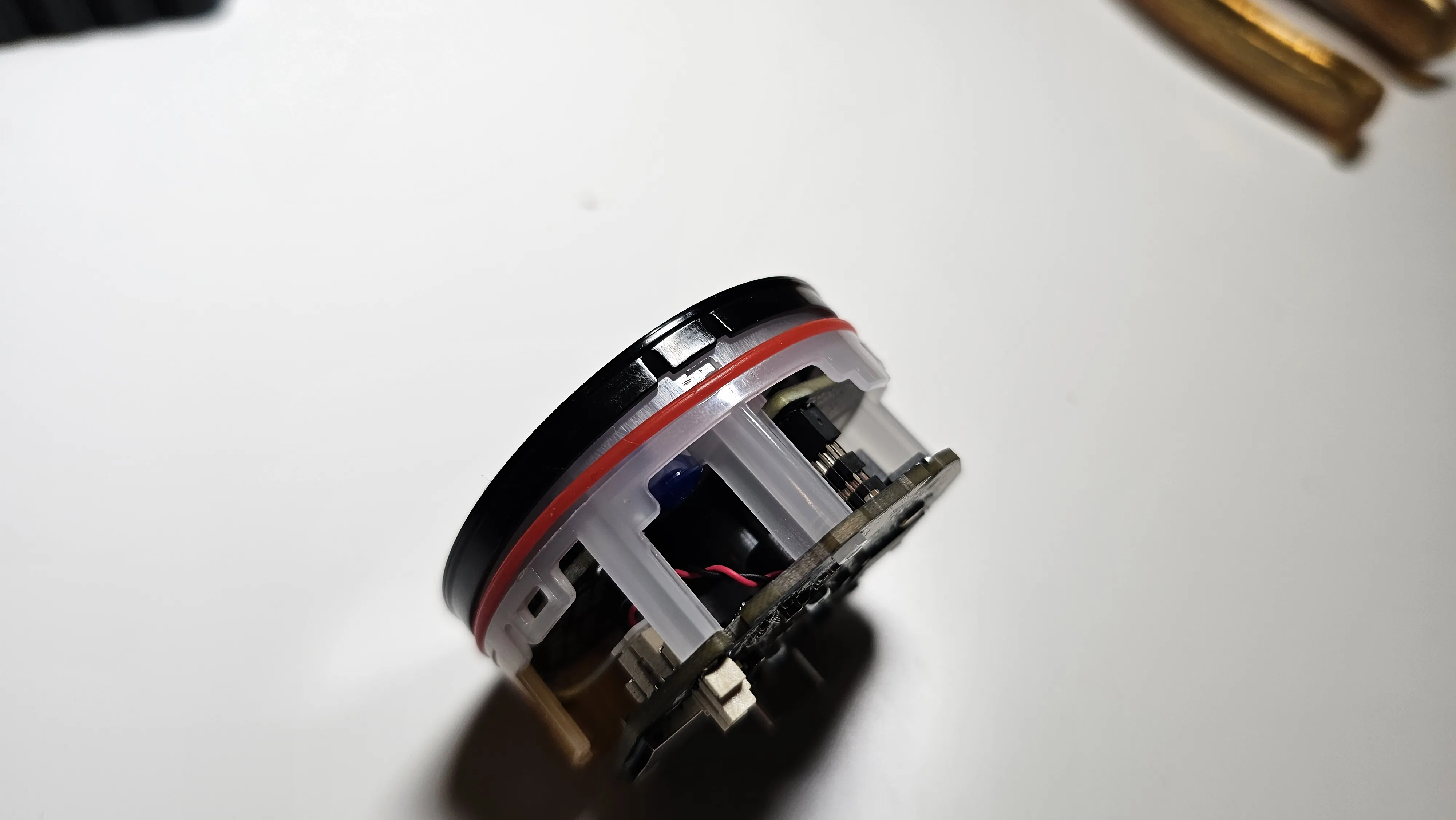
disconnect the front black cover by unlocking 3 clips with a small pry tool
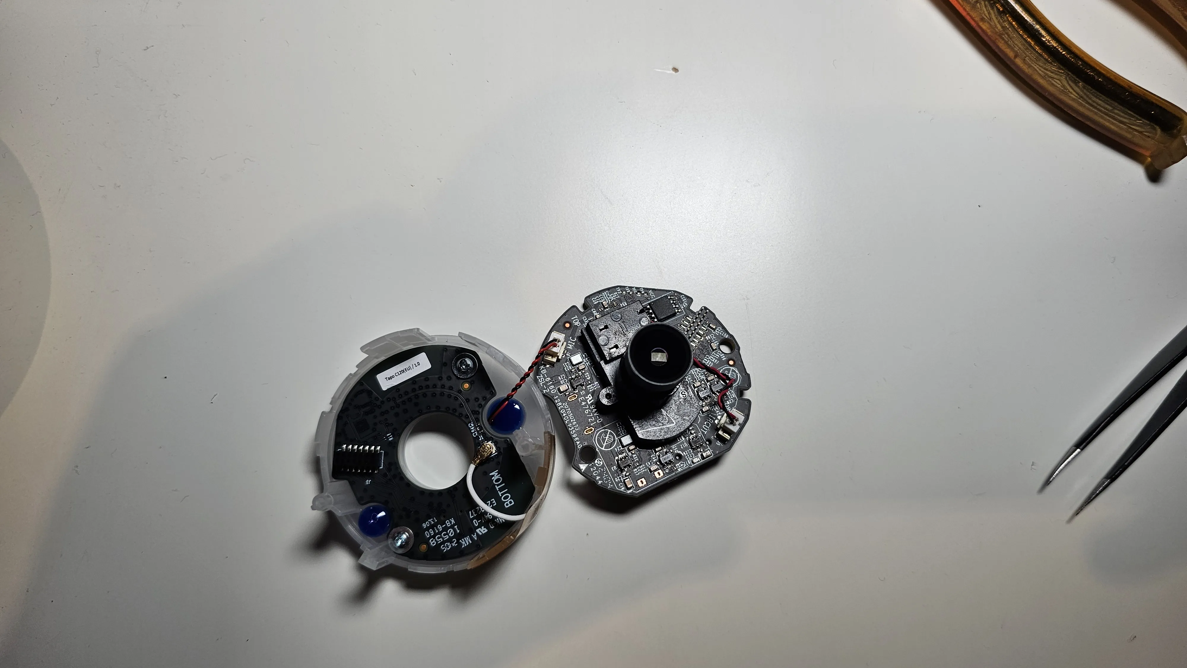
gently slide out the main pcb holding the camera lens and disconnect the wires for microphone
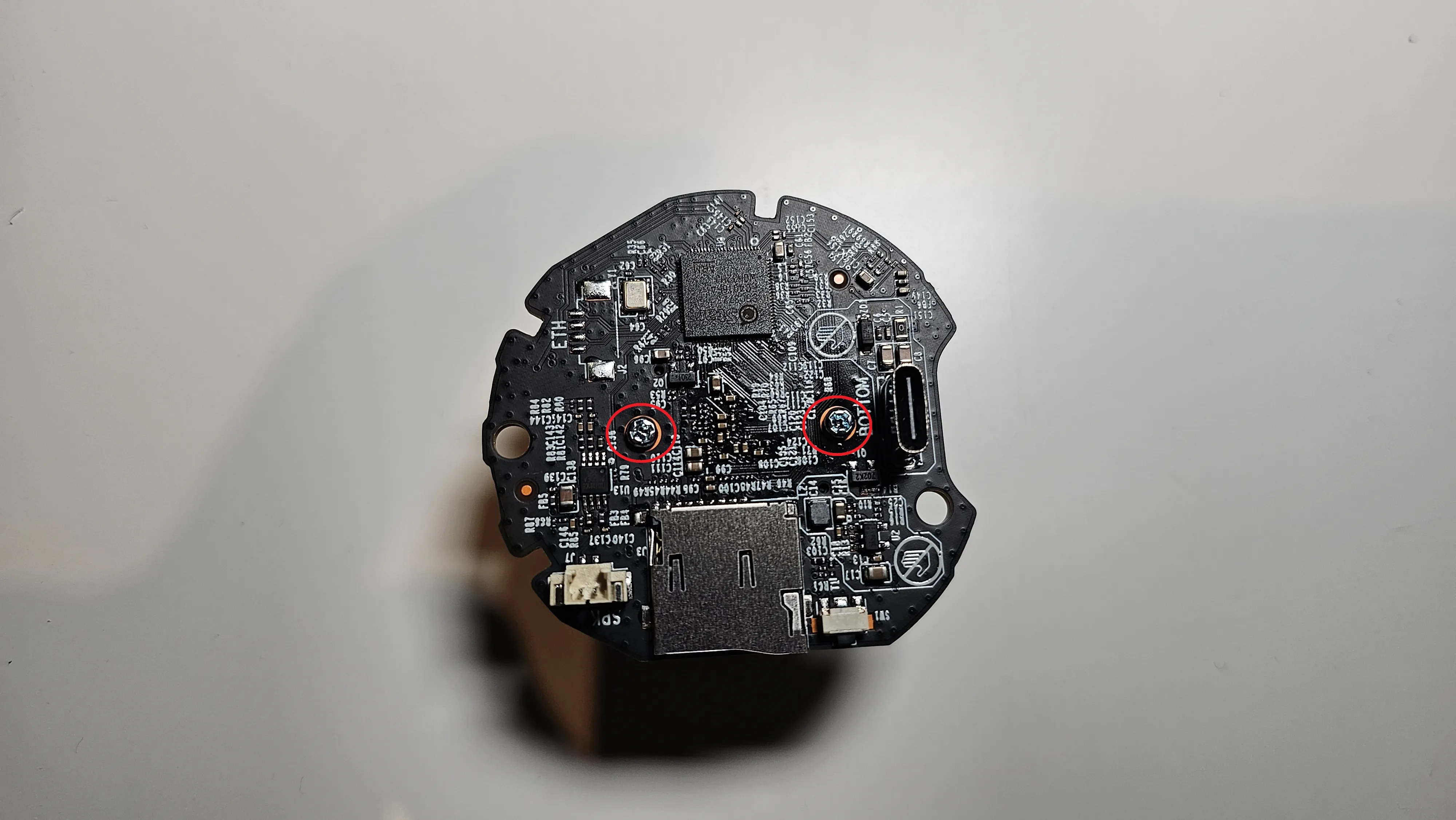
unplug camera lens wires and remove the 2 screws marked on the picture below to take the lenses off the pcb
NOTE: do not touch the sensor hidden behind lens, any damage or even dust will severely affect the video quality or even result in camera not working)
remove the glue applied over lens
- do not try to force unscrew the lenses, it won't work and can only damage it
- use the crafting knife to gently remove the bulk of glue (it takes a while, you'll get there, trust me)
- the glue is also deeper inside the lens enclosure, you can try to force it out with the knife or use the heat-gun and heat it up for few seconds, need to be careful though, too much heat can damage the plastic components.
- unscrew the lens counter-clockwise and remove any remaining glue
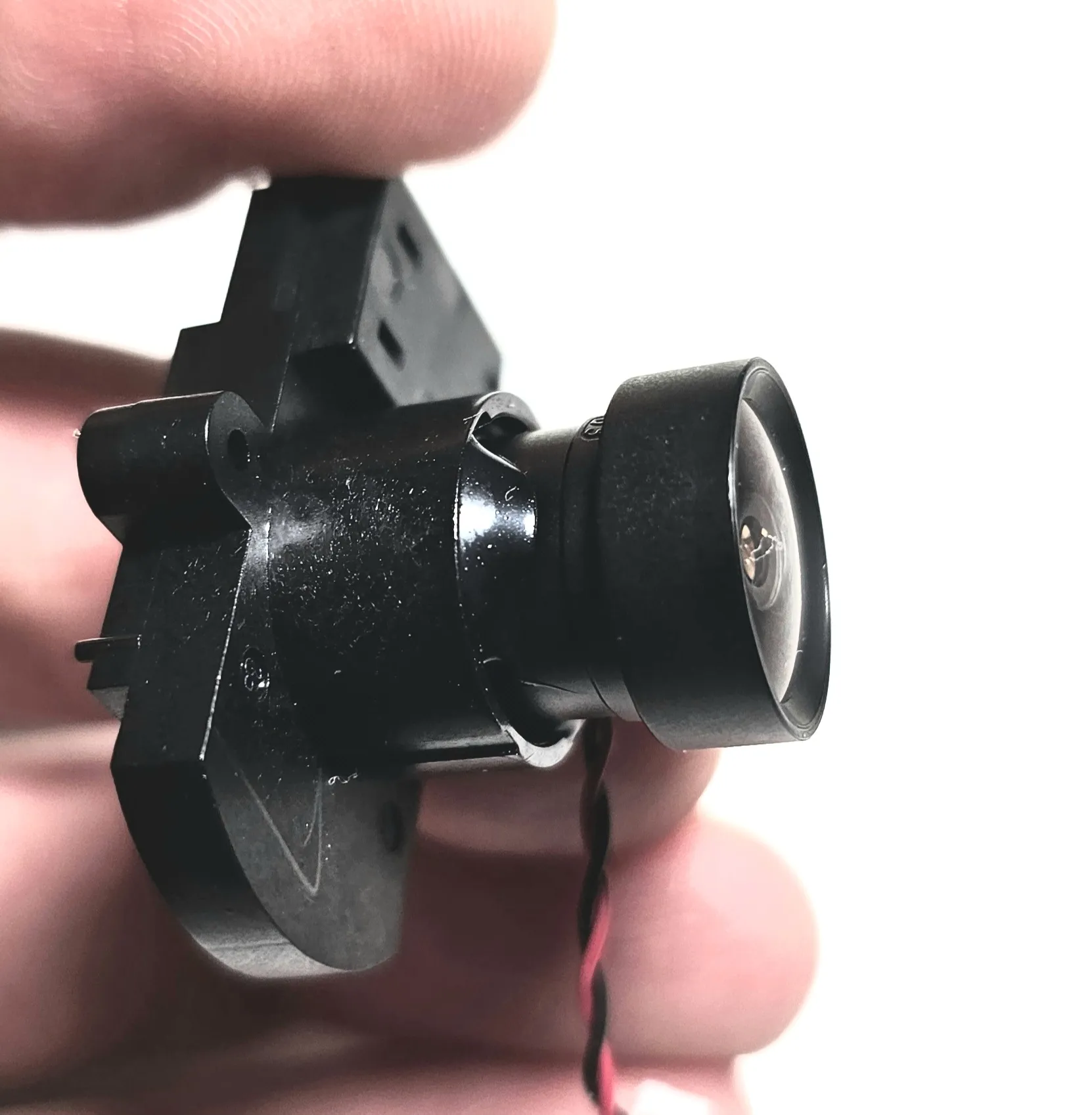
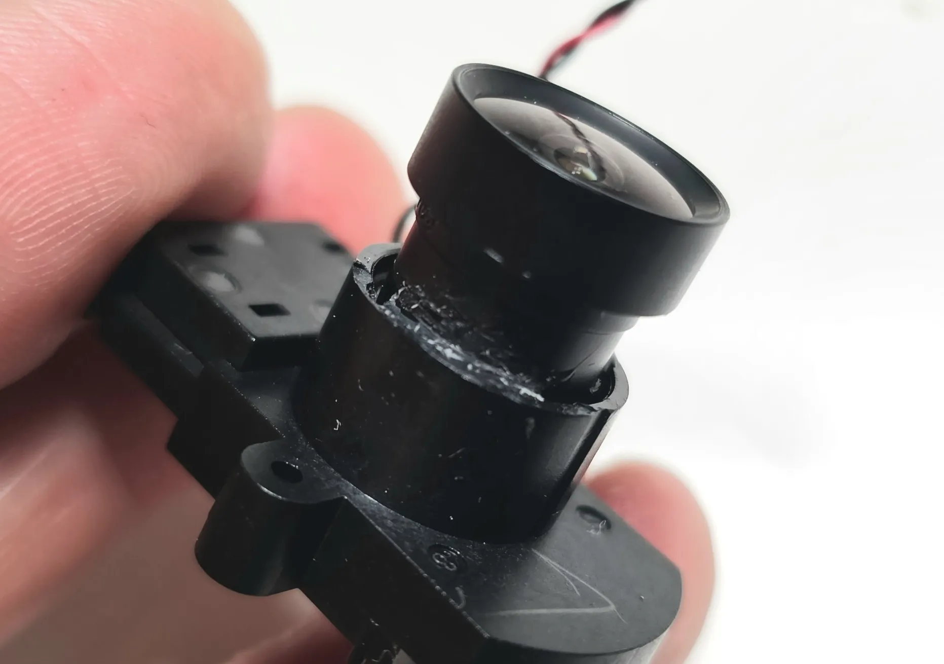
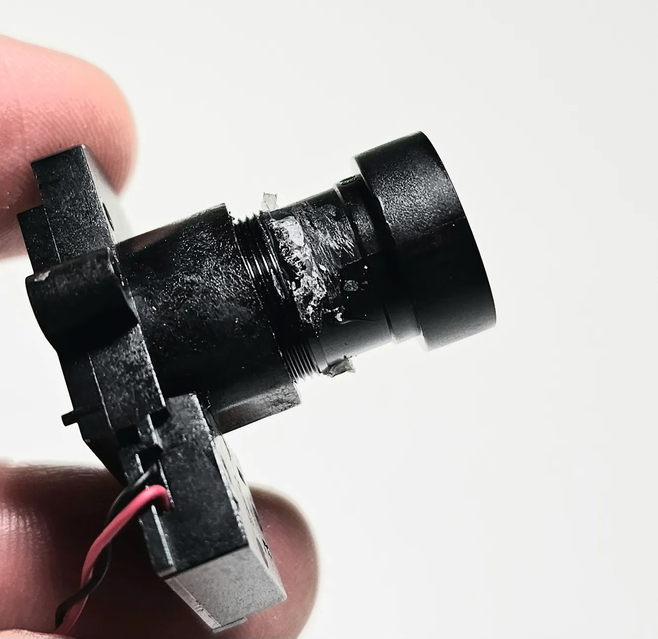
- The next step is to focus the camera, this can only be done though when it's mounted on the printer and put together into enclosure, you can reverse all steps and put the camera together, but I would highly recommend to follow the remaining steps to make the focusing much easier
take out the second pcb by removing 2 screws and disconnecting the wifi antenna
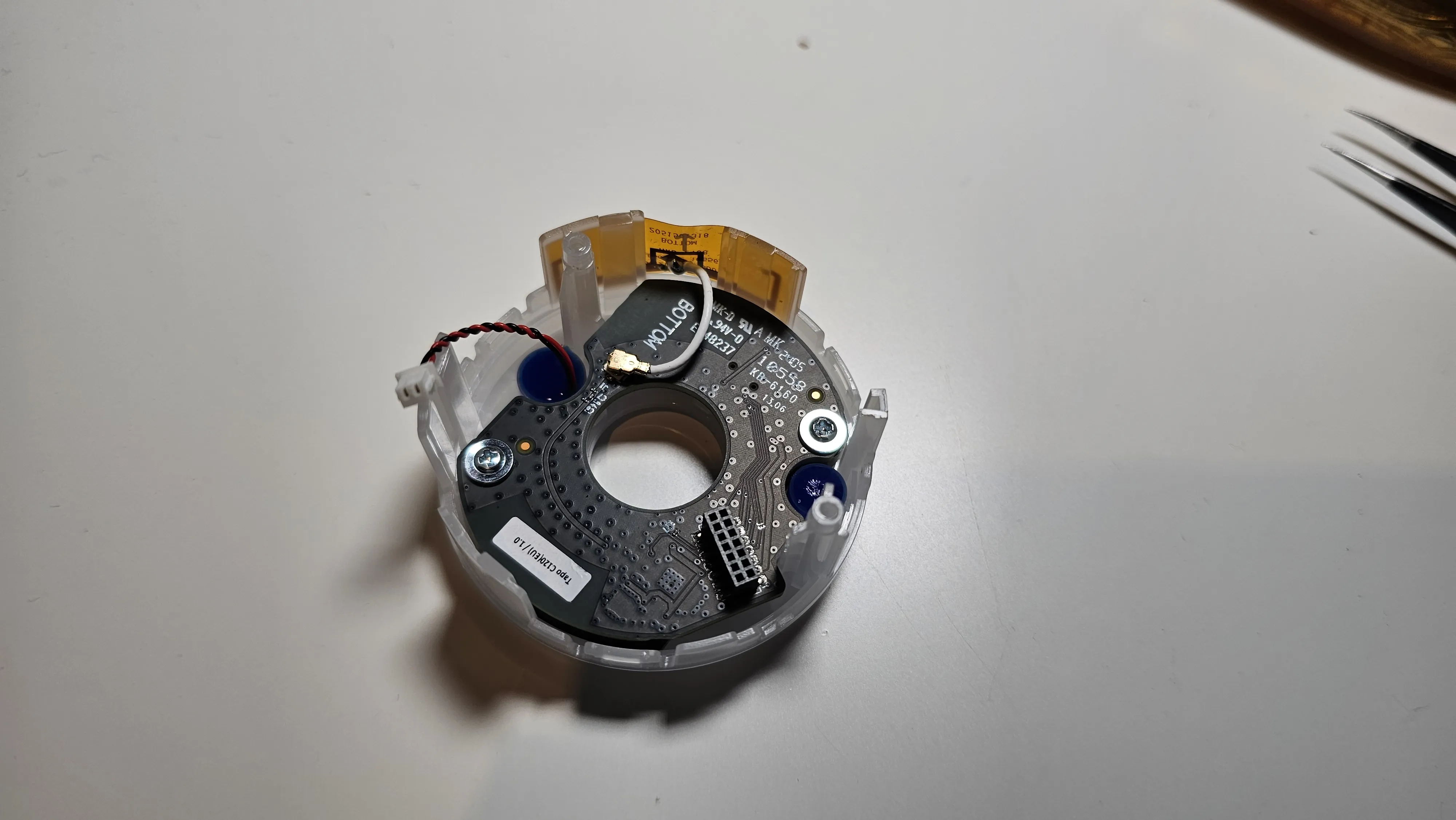
- pay attention to the 2 black stand offs between LED and wifi pcb's, do not lose them!
take out the black rubber seal, this will allow you to rotate the lense even after the camera is fully assembled, this will obviously result in the camera not being waterproof anymore, but I don't believe that's relevant if it's attached to the printer
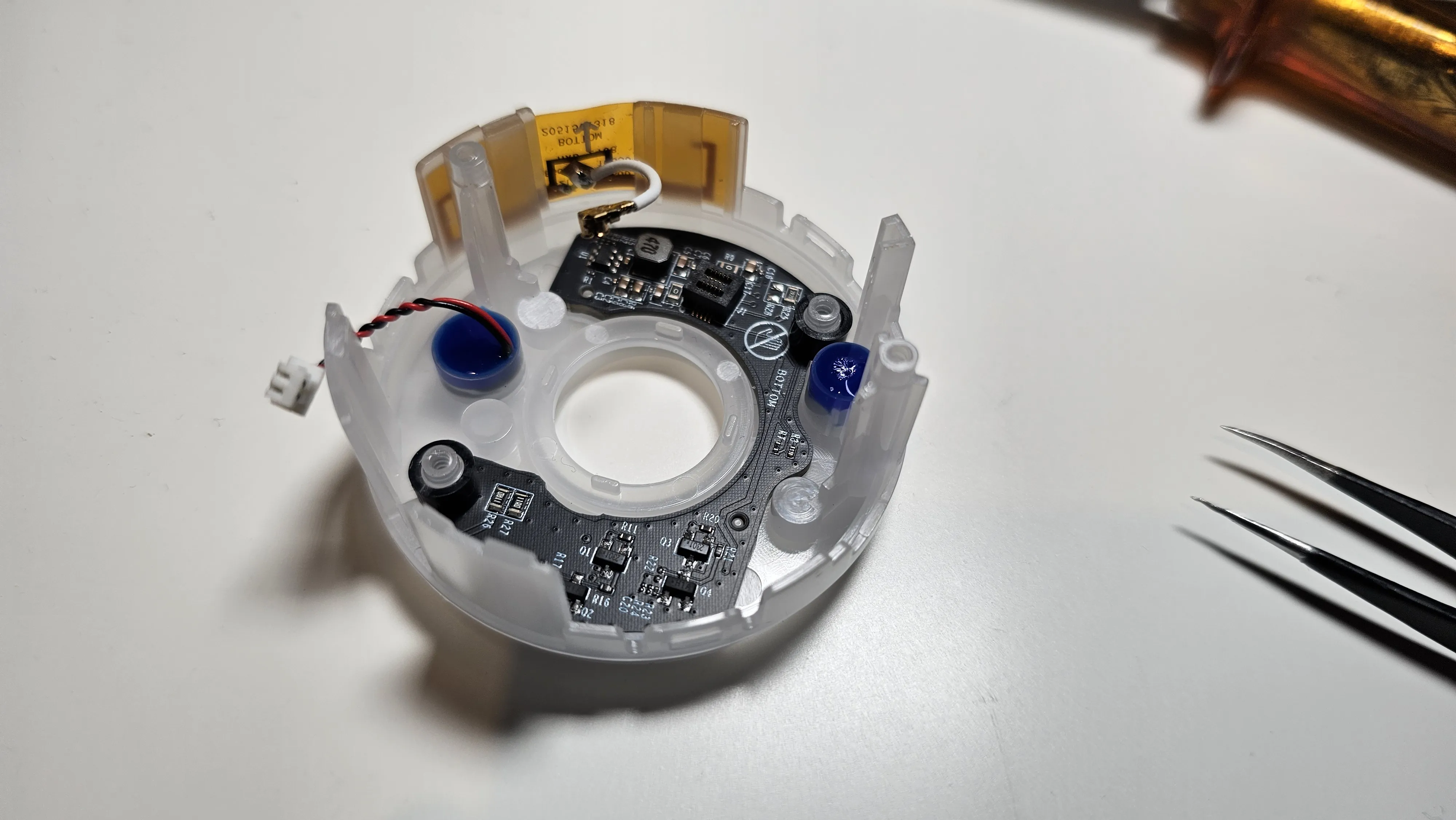
- Reverse all the steps to put the camera together, apart from the front black cover
Mount the camera to your printer, plug in the usb C power cable, turn on the preview on tapo app and set the desired focus
- when done it's worth putting a bit of hot glue around the lense to prevent it from loosing focus due to printer vibrations
Please be aware that following this guide you will loose your warranty and can potentially damage the camera. I do not take any responsibility for loss, damage or injury as a result of following the steps described. If you decide to make the modification you are doing it on your own risk.
License

You shall not share, sub-license, sell, rent, host, transfer, or distribute in any way the digital or 3D printed versions of this object, nor any other derivative work of this object in its digital or physical format (including - but not limited to - remixes of this object, and hosting on other digital platforms). The objects may not be used without permission in any way whatsoever in which you charge money, or collect fees.


Comment & Rating (14)