Search models, users, collections, and posts

The Great Calibrator: REVOLUTION
IP Report



Print Profile(1)

The Great Calibrator: Revolution
Designer
7.3 h
10 plates
Open in Bambu Studio
Boost
140
437
49
20
515
164
Released
Description
EDIT MONDAY JUNE 22 : THE GREAT CALIBRATOR 2026 IS OUT! IT'S WORTH TRYING!
CLICK HERE AND LET'S GO THERE!
"The revolution has begun… "
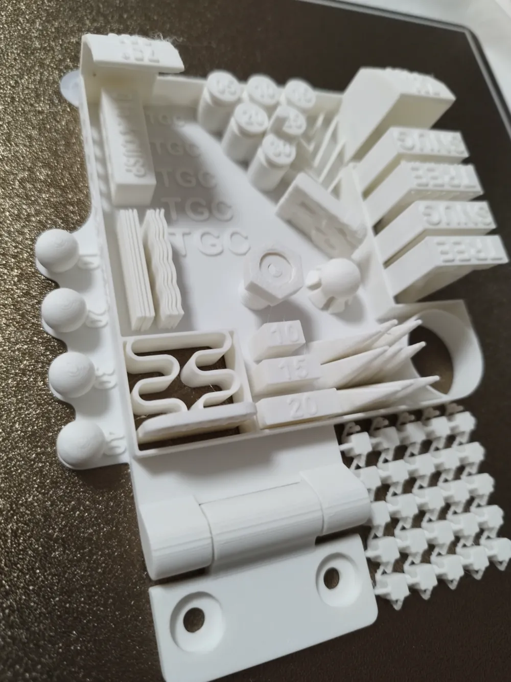
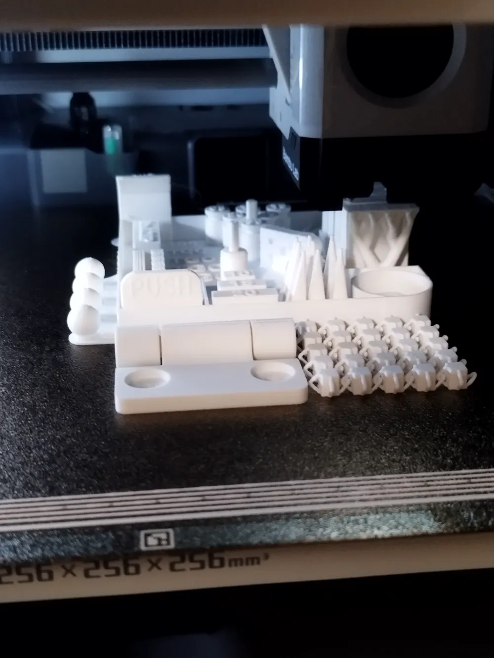
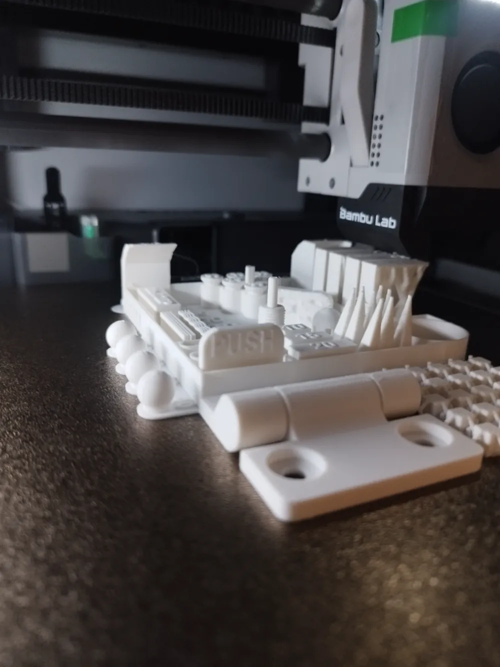
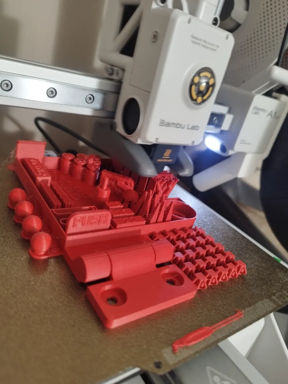
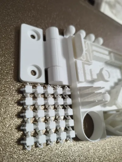
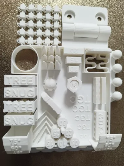
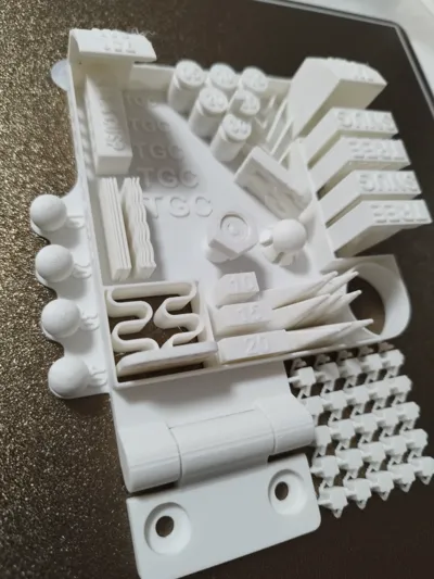
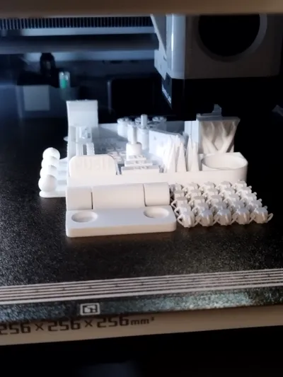
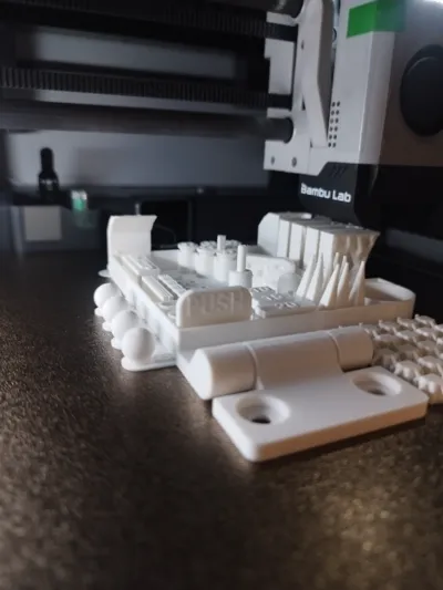
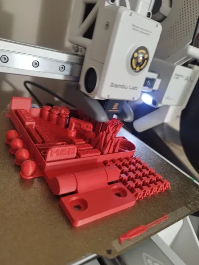
Here is the brand new model of the Great Calibrator: REVOLUTION
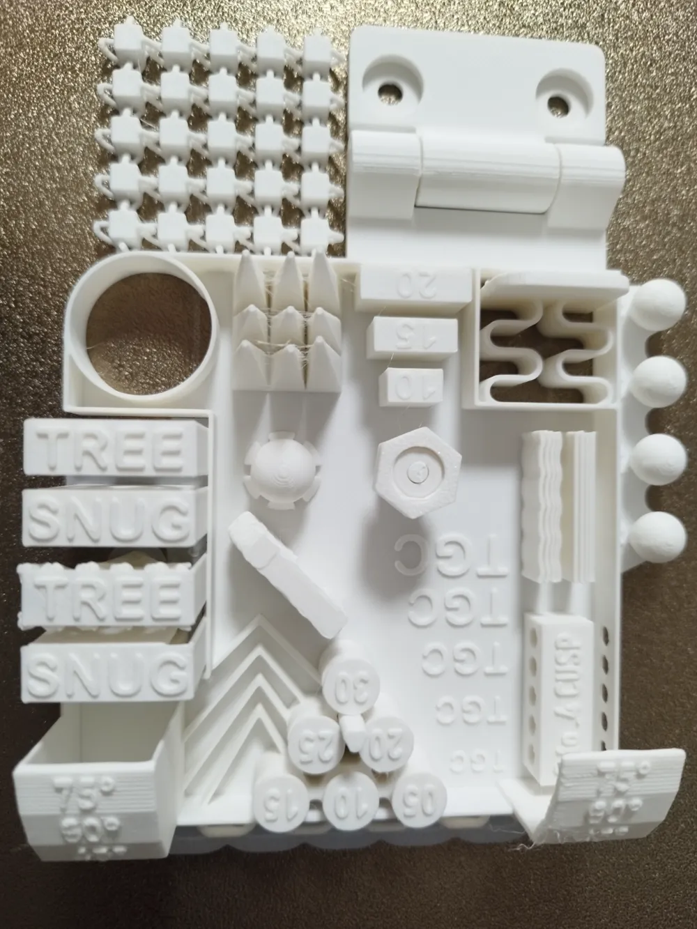
Many new features are present in this version:
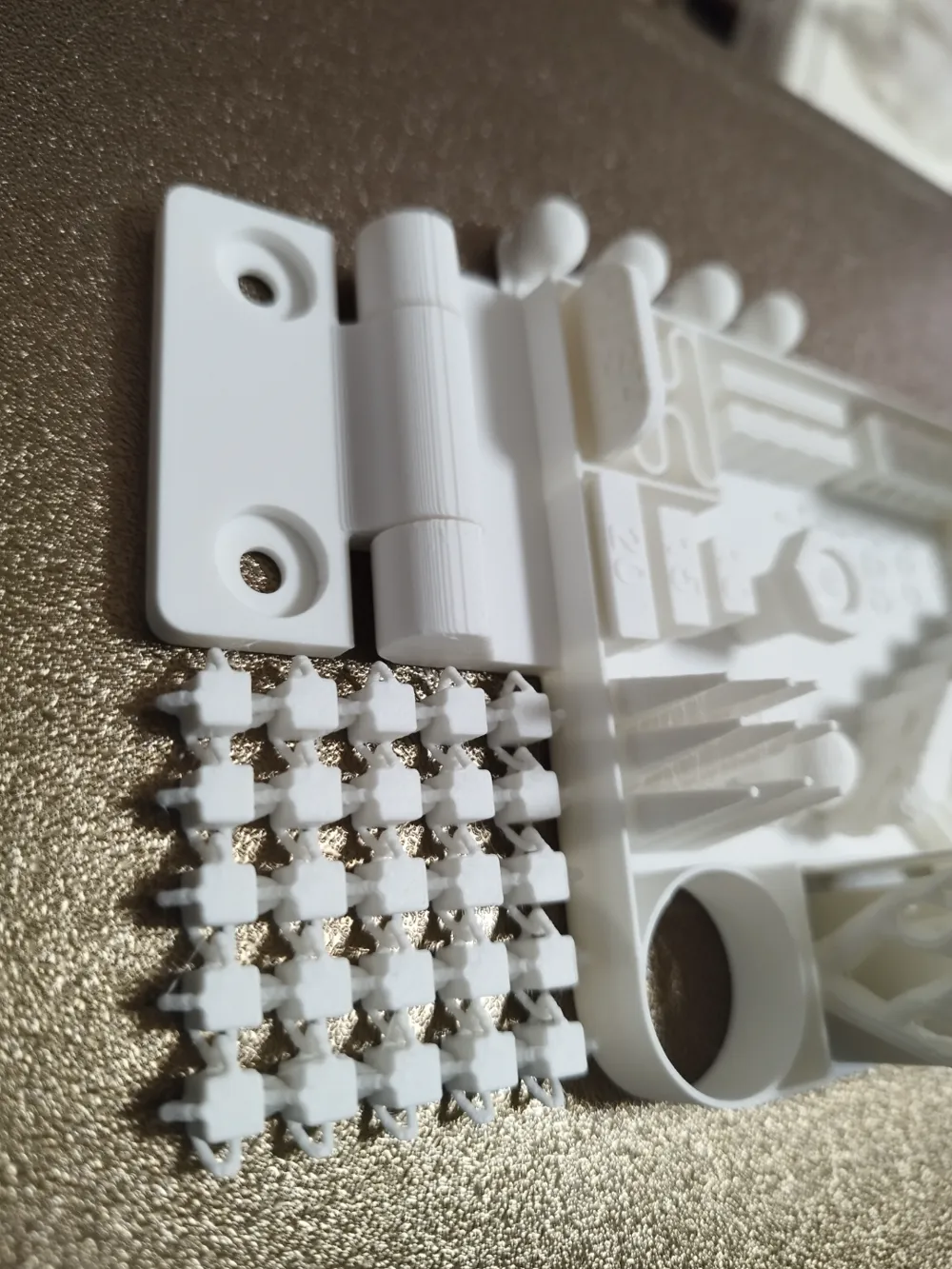
- The hinge has been completely redesigned
- The moving spheres remain on the left side while the removable ones are concentrated in a single larger central sphere with a removal ring to facilitate gripping
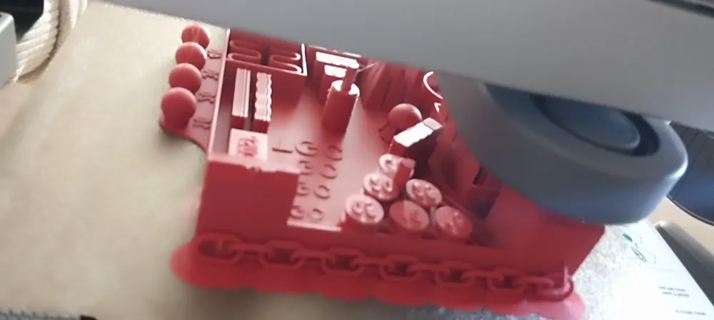
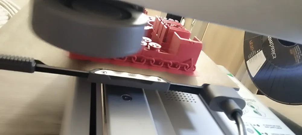
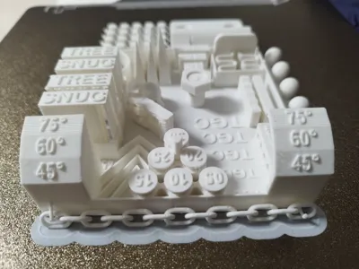
- The chainmail has been placed to the front of the model
- Tolerance pegs have been repositioned for easier access and manipulation. They also have an additional peg in the center to be inserted into the various holes present
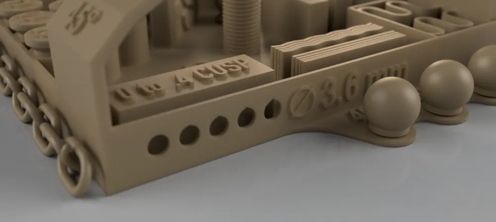
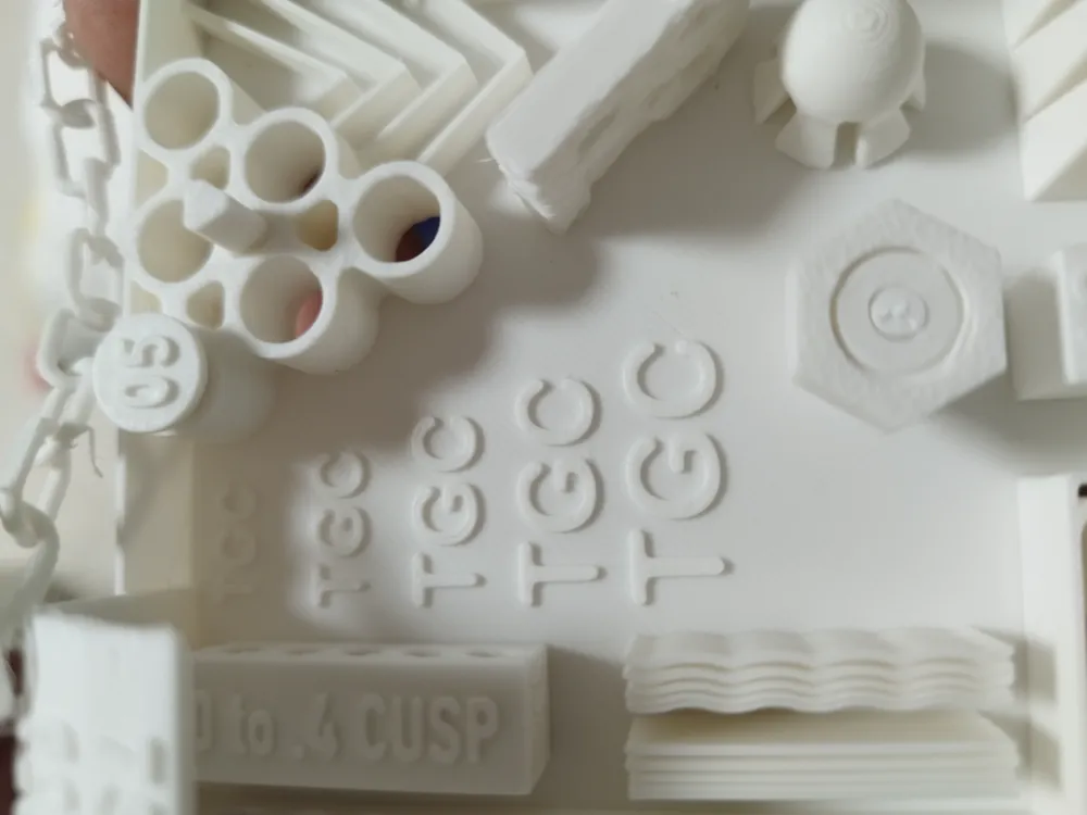
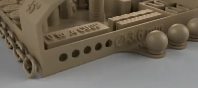
- On the left of the model, under the overhang test, there is a new horizontal drilling test. The test stick is in the center of the inevitable bolt (the nut is instead in the usual position). The horizontal holes have a cusp of different heights (0.1 mm between each hole) so that in horizontal printing the circular shape is respected as much as possible.
- V-shaped lines of different angles have been added. They will be used to check if the printer is using a good flow pressure (
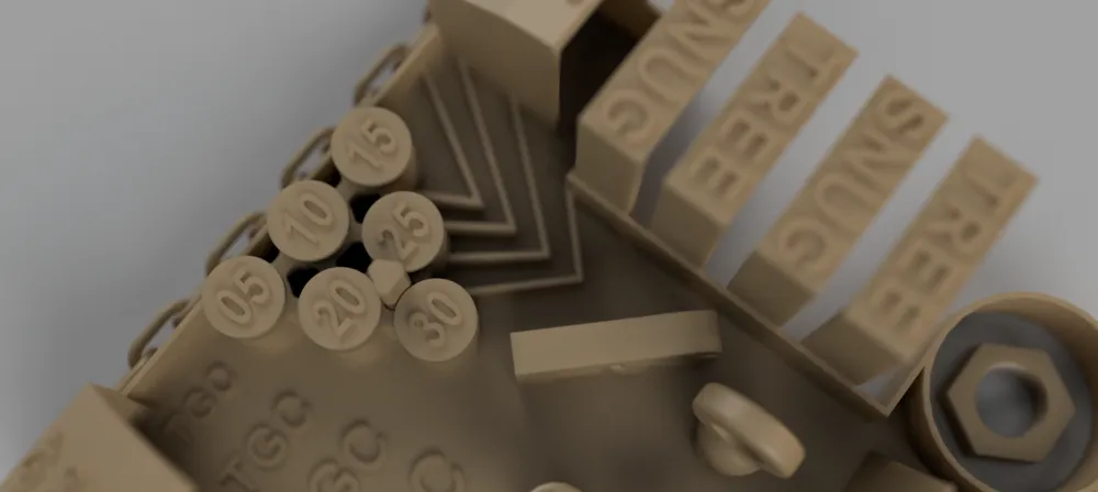
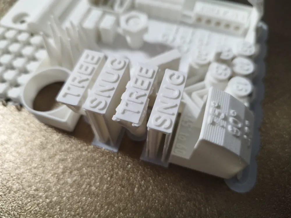
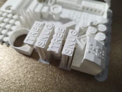
the vertex must be as linear as possible without cambers or underextrusions) - New presences for a new test: four right-angled structures will be printed with supports in snug and tree mode. Two structures have a flat ceiling, the other two have a rounded one. Which support works best? And which is easier to collect?
- A further novelty is the presence of an "FS" element i.e. Fuzzy Skin to test this mode.
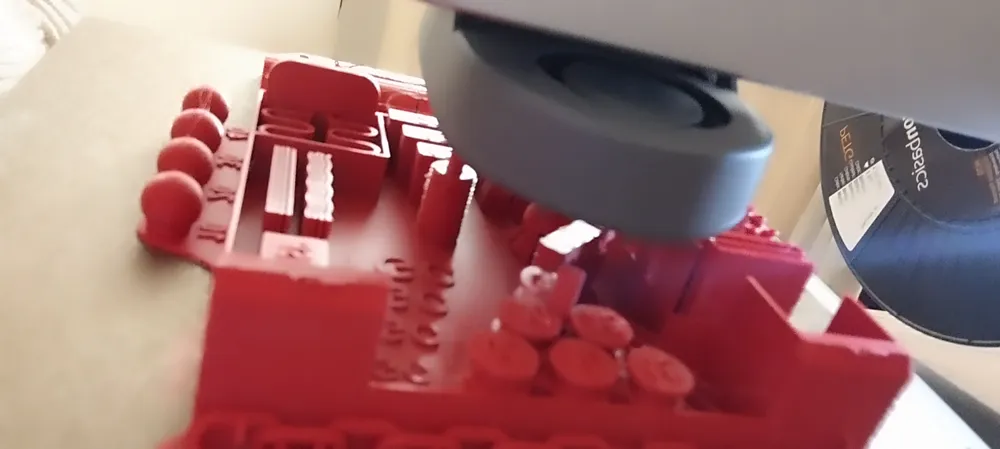
- A great innovation for the Revolution version is the presence of a different plate for each element (in addition of course to the complete model) in order to be able to choose a single test if you would like to concentrate on just one of them!!
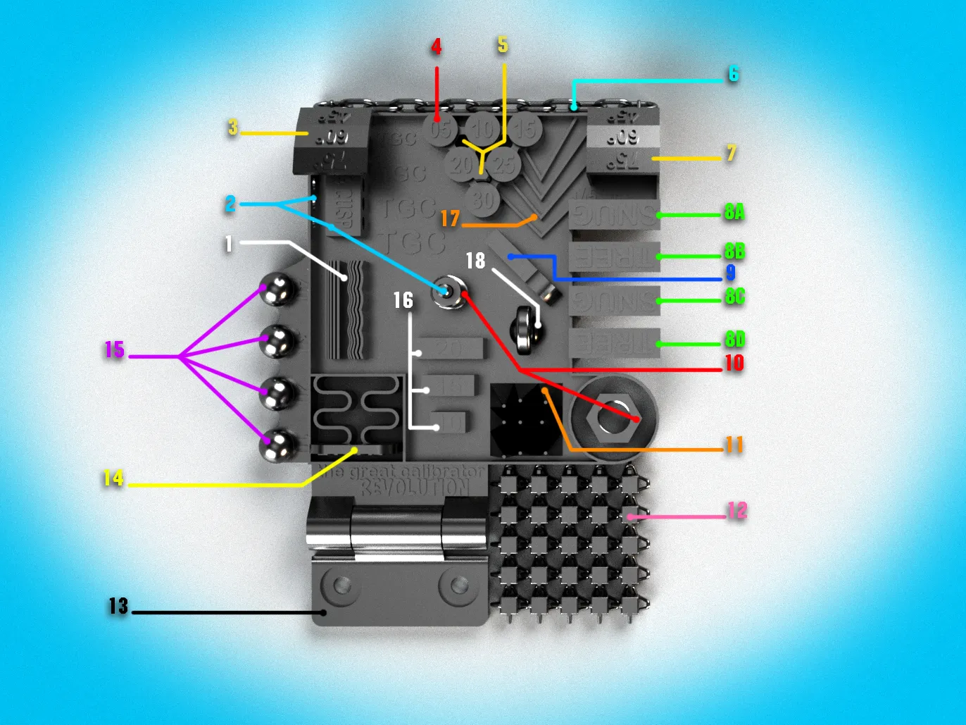
- 1 - Straight and wavy lines - These lines start with a thickness of 0.40 mm and a distance of 0.10 mm. thickness and distance gradually increase by 0.10. They must be printed continuous, clear and disconnected from each other
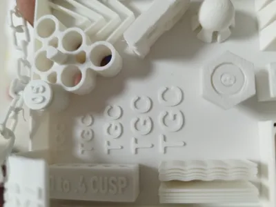
- 2 - Necessary cuso for circles on vertical walls - In the middle of the bolt is placed a little round bar to insert into the five holes.
These holes are built using a top cusp to maintain as much of the circular shape in a verticle wall as possible. The distance between the tip of the cusp and the circumference increases from 0 to 0.40. Use the view and the bar to identify which cusp to use in your projects, both from a functional and aesthetic point of view. - 3 - Progressive overhangs - This bar will test the ability of your print to build acceptable planes at slopes of more than 45°.
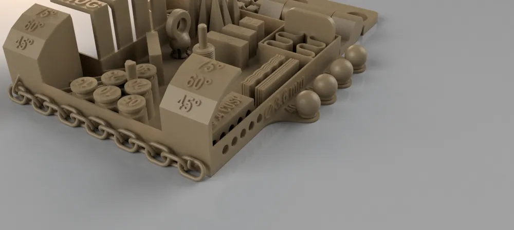
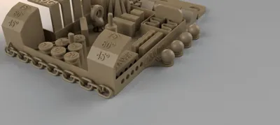
Starting from a vertical 90° angle it tests the 45° (which every printer should be able to print) , the 65° and the 75° extreme angle. These lasts can produce spaghetti on the bottom but a calibrated printer should be able to build and read the numbers on the top. - 4 - Horizontal tolerance pegs - There are 6 pegs in their logement. Every peg has a different tolerance. From an easy 0.30 mm to an incredible difficult 0.05mm. To test the pegs you should press on it. if the peg cannot be freed by pressing with the fingers it is useless to continue with the use of instruments. The last free peg will be the tolerance you will have to provide for these horizontal parts to be functional (normal calibrated printrers should be relatively easily free the 0.15 peg)
- 5 - Additional horizontal tolerance: more complex form - To carry out this test you must first be able to remove the bar located above peg 30 from its housing having a tolerance of 0.20 mm on each side. If you are unable to extract it, the test must be considered already failed. The slot below peg 10 has a tolerance of 0.15, the one above peg 25 has a tolerance of 0.10 while it will be 0.05 for the one above peg 20
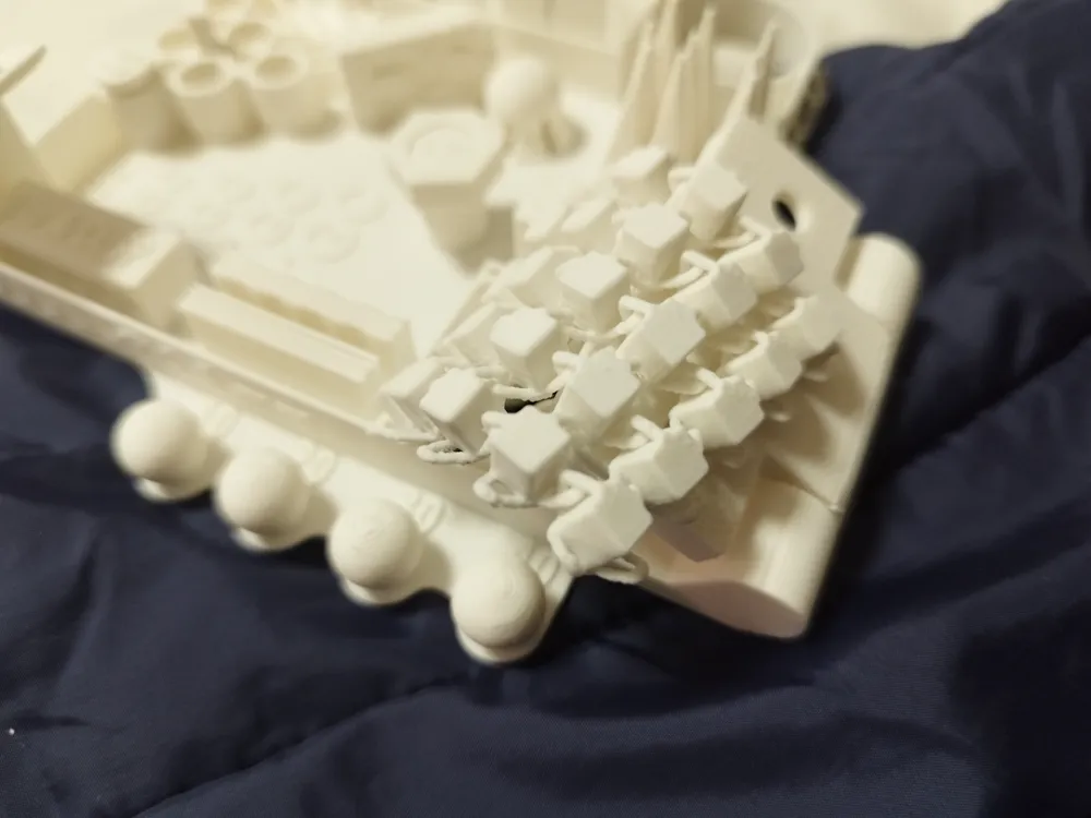
- 6 - The Django chain - Your printer will try to build a chain whose links are made of tubes with a diameter of just 1.6 mm. In order to overcome printing problems, a brim will be placed under each ring, in contact with the plate. Be delicate when removing this brim and detaching the model from the print base. Django's chain can only be released from one side...
- 7 - The bridges - This bar has the same slopes as the overhang one (3) but it's surronded by vertical walls transforming overhangs into bridges. Your printer should be able to complete this bar without any pronounced artifact on the bottom.
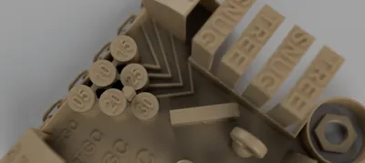
- 8 (A-B-C-D) The support test - This is the biggest new in the big calibrator series. There are four horizontal walls at a height of approximately 30mm, two of which are flat while the others are rounded at the bottom. These walls will be built using snug and tree-type supports. The aim is to verify that all the walls are correctly constructed and to have the possibility of evaluate which solution may be the best with the current calibration and the filament you are using. Obviously, consider carefully not only the appearance of the lower part of the walls but also the ease of removing the supports themselves.
- 9 - The FS: Fuzzy Skin - This an effect owned by bambulab studio (and Orc slicer) to produce fuzzed external walls on your printings. The fuzzy skin is able to hide the layer separation appearance. With this test you will be able to see what a print will look like using this effect
- 10 - The nut & bolt - This is the classic test to see how your printer can be functionl for mechanical parts. The nuts and the bolts have a little 0.2 mm tolerance but considering that the thread has an inclination greater than 45°, screwing could be difficult. If it feels hard it won't be a problem but it shouldn't get stuck or require the use of a tool.
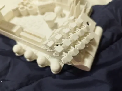
- 11 - The stringing “pyra-cones” - These pyramids evolving as cones aren't parallel but are all inclined differently to test the stringing in the most stressing way. With this configuration you will probably never be able to obtain a print without any stringing but you will have to try to reduce its presence by adjusting the printing preferences (and entertaining and choosing the filament according to good standards). Important: Respect the drying instructions.
- 12 - The chainmail - It's a delicate part of the printing and it has been engineered not only to test the printing ability itself but also to train yourself in removing little and fragile parts from the bed plate. Try to maintain the integrity of the chainmail. The hooks on the calibrator borders aren't relevants. If they broke you won't have to worry about it.
- 13 - The hinge - Is one of the “print-in-place” part to test if your printer is in measure to do such kind of printings. The printed hinge should be easy to accomplish its movement without any resistance. Having large tolerances and thick parts it is not very indicative for precision pieces but useful and functional for objects such as dragons, snakes and other articulated objects....
- 14 -The push plate - This part of the calibrator is made up of a plate connected to two compressible elastic structures. It is precisely used to test whether the material is very elastic or too rigid for projects that involve the use of filaments with this type of property. The elasticity can be tested in horizontal and vertical manner if needed.
- 15 The moving spheres - These spheres are printed in place on top of other internal spheres with tolerances varying from 0.10 to 0.40 mm with steps of 0.10 between them. The purpose of these spheres is to make them mobile while remaining in place (they may require the aid of a fine blade to detach the lower edge from the base, taking care not to damage the support peg inside them). Considering the FDM printing method (see and read the article and model on https://makerworld.com/en/models/568875) it will be practically impossible to free the movement of the spheres with a tolerance of 0.10 and very complicated for those of 0.20 while the spheres of 0.30 and 0.40 should be relatively easy to free if you were using the standard 0.20 mm layer height. Greater chances of success could be had with thinner layers (on the contrary, increasing the thickness of the layers will increase the difficulty). This is the test to be taken into consideration for the calculation of tolerances in projects that require the greatest possible precision in the "print-on-place" method.
- 16 - the measurement boxes - printed to be measured by caliper, these blocks must as much as possible maintain the exact dimensions of 10, 15 and 20 mm in width and 6 mm in height. A deviation of the order of 0.15 could still be considered acceptable. In the same way, measure all the edges of the calibrator which must have a thickness of 0.80 mm.
- 17 - the V shapes - This shapes are useful to consider how your print is calibrated on the Pressure Advance. The tips of the shapes must be as pointed as possible... if roundings, bubbles, deviations or separations of walls are noticed then a further adjustment of the pressure advance should be envisaged.
- 18 - The removable sphere - Recognizable because it is equipped with a ring to grip it, this element is similar to the mobile spheres n° 15 but has a wider tolerance as its purpose is not to measure this quality but to see how elastic and resistant the filament is for creating interlocking parts. The base is in fact freed into 6 segments which should allow the element to be removed from the rest of the model. Before pulling upwards, make sure to free the part near the base by turning the element horizontally clockwise and anticlockwise and using a tool to facilitate its detachment. Warning: Not all filaments have properties that allow them to be used for this purpose. One material, one brand, one wet filament can be brittler than another. Should one or more of the legs break in freeing the piece, consider using a different film for such a project.
Feel free to contact me for more explications or help on the using and on the reading of your printed calibrator!!
Happy printing, mates !
License

This user content is licensed under a Standard Digital File License.
You shall not share, sub-license, sell, rent, host, transfer, or distribute in any way the digital or 3D printed versions of this object, nor any other derivative work of this object in its digital or physical format (including - but not limited to - remixes of this object, and hosting on other digital platforms). The objects may not be used without permission in any way whatsoever in which you charge money, or collect fees.


Comment & Rating (49)