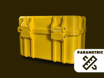
This parametric container is ideal for creating suitable cases for various tools and small parts. The internal dimensions and some geometries can be changed via the parameters. The container is created in the generator on a single print layer. The generated stl file in Bambu Studio can be split into several printing plates using the split object function.
Split stl into multiply objects
In addition to the dimensions, you can also decide whether a hinged lid or a lid that can be removed completely should be generated. Depending on the selected parameters, different screw lengths must be used to assemble the container. It is recommended that lockclip_size+2*rip_thickness is a multiple of 5mm so that standard screws can be used.
If there are any problems with the generation of the files, please write me a message so that I can fix this as quickly as possible.
I hope you like the design and I would be happy if you upload the finished containers as a make.
CUTOUT GENERATOR
In addition to the online version of the generator, the files also include a version that only works directly in OpenSCAD.
In this version, dxf files can be imported to create suitable cutouts for tools. The cutout generator is still in the test phase and cannot be used online because the dxf import function is not available in Makerworld. I hope that such a function will be integrated in the future. Instructions for this function can be found below.
INSTRUCTIONS
On Makerworld its not possible to upload .dxf Files into the generator so this generator does only work directly on your PC.
Step by Step introduction:
Dowload Openscad and Inkscape (you can use other program to generate the dxf file)
Make a photo with a ruler to scale it in inkscape. NOTE: The best way to do this is using a scanner because it automaticly has the right dimensions. Open it in Inkscape and make the following steps. It is necessary that the Dimension of the .dxf is correct!
Draw an outline with some tolerance and set the unit to mm or inch (Image 1)
delete the image and press [CTRL+SHIFT+D] and adjust the document size to the outline (Image 2)
OpenSCAD / dxf can't read this line format. What we need to do is convert it to a path. Drag-select your outline and Press [Shift+Ctrl+C].
Select the node tool [N], and notice how the handles on the object now look like gray squares. This indicates we now have a path.
press [Ctrl+A] to select every node. With the nodes selected, notice how the handles changed again. With every node selected, initialize some mouseclicking action on the indicated button "Insert new nodes into selected segments"(Image 3 (1)).This inserts new nodes into selected segments, following the curve. With still every node selected, press the indicated button to "Make selected segment lines". (Image 3 (2)). This step generate only straight lines.
Now save the file as .dxf (R14) with the right units. It must be saved in the same path as the “ParametricRuggedContainerAutomaticCutout.scad” File
Open the “ParametricRuggedContainerAutomaticCutout.scad” File and insert the Parameters cutoutlength and cutoutdepth. (Image 4)
Measure the height of the Tool and insert the size into “cutoutheight” (Image 5).
Now adjust all the other sizes. Be aware that the height and height top are dependent of the cutoutheight!
Have Fun with ur new Toolbox
Image 1: Outline the objectImage 2: Adjust the docoment sizeImage 3
I really like the setup!
The only problem I have is the alignment of the locking clips.
With 2 Clips the bed alignment is not okay, also the clips are in the model.
if you notice, when using large lock clip size and large rip thickness the hole does not go all the way thru. I didn't notice until I printed it, I will fix it with a dremel tool
EDIT: I tried looking at code, but I am not great with OpenSCAD and I don't know German! Thanks for the model, hopefully this can help make it more robust!
well not the best print. i tryed petg with the green (maybe needed to be dryed, first try, stuff to work on) and pla for the red. had a few issue base wasnt printing corner and i need to fix the manifold with the top. havent put hinge pin in yet. but feels like they wont open or fit, when open. tomorrow project. cool thing. i mite try a smaller tip with slower print at a later date.
tolerances on the hinges are a little too tight basically had to thread the m3 screws into the holes. unfortunately my a1 mini decided to not be amazing at printing the hinges on the lid and the imperfection that it laid down made a weak spot that cracked right apart when screwing in the hinge screws. despite the tight tolerances it otherwise printed the bottom amazing, and the latches work great. Will give the lid another shot tomorrow when I get home from work.
Excellent design and great instructions. I set all of the sliders down to their minimum settings to test a print. I had to set 'detect thin walls' due to having wall_thickness set to 0. There were visible holes in the printed walls, but container is still functional. I suggest setting minimum value for 'wall_thickness' to 1 instead of 0 so user cannot set 0 value. Overall the design is perfect!
Came out great! Had to only print the latch by itself and then move the box down because the box and the latch were not on the same plane. If there was a way to separate each component to its own stl would be great too, but probably a limitation of the generator. Easy enough to fix in the slicer.
Firstly, this is awesome, thank you for sharing. Secondly, is there a way to easily display the inner dimension? That way, if we wanted to install sorting trays, we will know what dimensions we need to use.
Im not sure if its possible to display it but th Dimensions are the ones you select in Parameters. With the r as radius at the edges and the bevel should be r/2. I will check this later. There is a new measurement function in bambulab if u want to be sure
update: I adjusted the Design so the radius is correct now. If u allready printed the box u have to measure the sizes in BambuStudio. In the updated version all sizes should be correctly. If not please let me know.