V-Spooler X


Print Profile(9)


Description
News: V-Spooler X Large bed edition is at Version 1.1 due to a mistake that affects one of the frame parts just on that model. The normal V-Spooler X remains at 1.0. The fix is only needed if you get the motor mod.
V-Spooler X is available free here on Makerworld but it would be great if you can support me by buying it here on Printables if you find it useful. A cheaper alternative is to join my club on Printables for at least a month, which gives you access to this and other models for the duration of membership. Also boosts are welcome!
 Want to build V-Spooler X? Get an authorised parts kit here!
Take the work out of finding all the different parts for V-Spooler X and let us do it for you.
There are options including the hardware kit and printed parts, or just the hardware kit if you would like to print your own. |
 Don’t want to build V-Spooler X?
You can buy a whole V-Spooler X in the same listing.
Upgrade kits and options are available, including the motor mod and various others. V-Spooler X is designed and manufactured in the EU, with affordable global shipping. |
| Currently we are under attack by unauthorised re-sellers illegally selling my work on various different platforms. Purchasing from my authorised manufacturing partner VisionToCreate3D directly supports my work, and several jobs manufacturing V-Spooler X in the EU. |
To help you with your build you can now also preview V-Spooler X in a web browser on your computer, or using AR on a phone or AR/VR headsets such as the vision pro here.
Please note we provide upgrade files separately in the profiles area so you can upgrade incrementally from any version.
Introduction
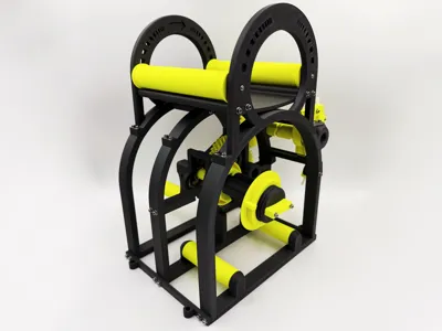
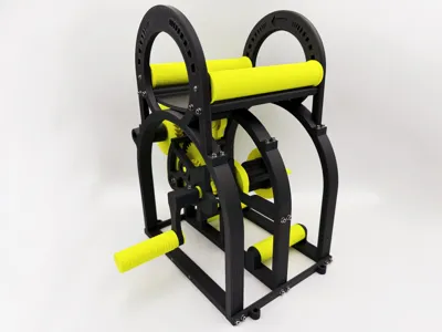
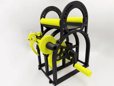
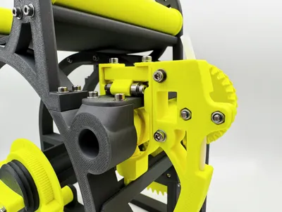
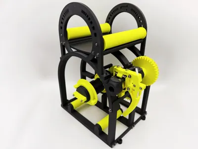
V-Spooler X is a re-spooler optimised for re-spooling to Bambu and Extrudr spools (will work with other same diameter spools) and is designed to occupy the smallest footprint in a vertical arrangement, hence the V in V-Spooler X. It is based on the original V-Spooler, but aims to support larger heavier spools.
I designed the gears in FreeCAD, the cam in Plasticity and did the rest of the project in Shapr3D. The model above was printed using Prusament PC-CF and Spectrum PETG-PTFE composites.
One of the biggest requests I get is for a video of V-Spooler X working, so here is a short video (currently features the old design of original V-Spooler, will be updated soon). If you would like to see how to load V-Spooler X please scroll to the bottom to find the tutorial videos there.
Which V-Spooler Should I Print?
| V-Spooler Mini | V-Spooler | V-Spooler X |
|
|
|
Additionally there is a “Large Bed Edition” version available for 3D printers with larger print beds and files prepared for the Bambu Lab H2D. This is slightly easier to build due to having less parts and has a slightly smaller bill of materiels.
Which File Do I Print?
You Want To Print A New V-Spooler X
V-Spooler X 1.0 - Bambu.3MF is the main pre-configured file for this model which is updated every release to include all changes, so you do not have to upgrade when printing a new V-Spooler X.
If you are looking to print the Large Bed Edition, please find the profile labelled for the Bambu Lab H2D.
You Want To Print A V-Spooler X Option
Look at the options section below and pick one, then go to the files area and choose either the Bambu or Generic 3MFs depending on your preference and print the matching file.
You Want To Upgrade V-Spooler X
V-Spooler X Beta 1 to 1.0 Upgrade - Bambu.3MF is the incremental upgrade file for Beta 1.
Required Components
The components lists below need checking, it is worth having a few spare of each item as I am prone to making mistakes despite trying to check this!
| V-Spooler X | V-Spooler X Large Bed Edition |
|
|
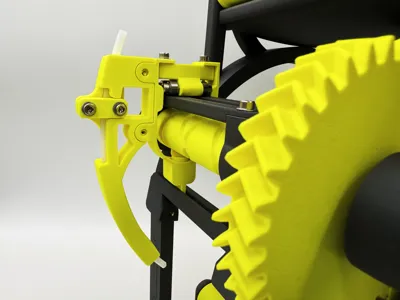
The helical compression spring can be easily sourced at Bambu Lab at the following links US/EU/UK/AU/CA/Global.
Please note that inserts require that you have access to a soldering iron and that those supplied by Bambu Lab are a slightly different size and less suitable. Ruthex or CNC Kitchen are good choices.
Optional Build Items
Loctite Blue
At least one of the screws as detailed in the instructions benefits from Loctite Threadlocker Blue. Do not use the red Loctite, it is too strong for plastic parts with inserts.
When you use Loctite Blue put a very small amount of it on the end before screwing it in. This is important for future removal. Please do not use this all over the model for ease of maintenance.
PTFE Lubricant
Plastic parts susceptible to friction benefit from lubrication. If you have a PTFE lubricant or other lubricant that is compatible with your choice of plastic, when final assembly has been completed a light greasing of the lead screw will help operation.
Optional Model Parts
V-Spooler X spindle and clamp options are now listed on a separate page here.
Upgrading From Beta 1
As this page is getting rather complicated, depending on your familiarity with V-Spooler X if you are performing an upgrade the best approach may be to disassemble your existing V-Spooler X and follow the instructions below using the upgraded parts in combination with parts carried over from Beta 1.
Assembly
Please find the relevant instructions for your model under the documentation section on this page.
Documentation (2)
License
You shall not share, sub-license, sell, rent, host, transfer, or distribute in any way the digital or 3D printed versions of this object, nor any other derivative work of this object in its digital or physical format (including - but not limited to - remixes of this object, and hosting on other digital platforms). The objects may not be used without permission in any way whatsoever in which you charge money, or collect fees.
Comment & Rating (1140)