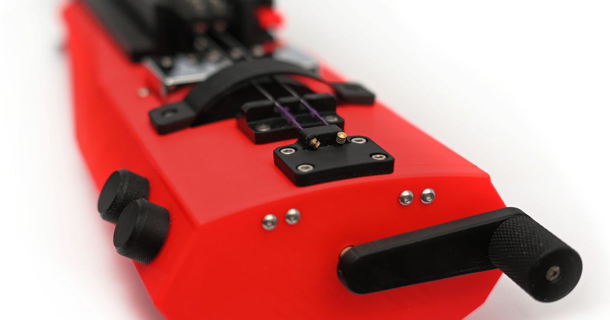
Electric Hurdy Gurdy (A1 Mini large project)
Electric Hurdy Gurdy (A1 Mini large project)


Print Profile(1)

Description
I printed and assembled this model from @demagnetized on Printables. My model is a complete project to make it super easy to print without any hassle. I've also added a spacer tube for the rod to make it easier to space elements on the rod but also prevent electrical interferences.
The project fits everything on the A1 mini bed and makes it easy to print. All parts are already configured to use the optimal settings for their use (i.e. the load-bearing/tension-bearing parts are set with more walls and more infill). You also have exactly everything you need to print in the right quantities.
The assembly is pretty obvious and goes from the bottom of the hurdy gurdy toward the neck.
Make sure you have your mic and knobs wired and through the openings before starting the assembly.
Last but not least, take a look at the pictures on the project to help visualize the steps
Assembly instructions
- Screw the tailpiece and the bridge in with 4 M3x10 each
- Put the bearings in the holes in body_01 and body_02
- Slide the electronics and wiring through body_02. Make sure you have them in the right direction
- Secure the knobs and the jack input with their respective nuts
- Mount the rod lock about 15mm from one end of the rod, the smaller part of the rod lock towards that 15mm bit. Secure the lock using 3 m3x6
- Screw in the 55mm spacer
- Screw in the wheel
- Screw the body_02 part into body_01 using M3x30 screws
- Screw the body_03 into body_02 using M3x16 and lock the rod using the second rod lock
- Mount the guitar pickup
- Screw in the internal frame to body_03
- Mount body_04 over the internal frame and screw it at the base
- Mount body_05 and screw it into the internal frame using M3x30
- Mount the body_06 and screw it into body_05
- Mount the crank
- Screw the keyboard_base into the internal frame using flat-head M3
- Mount the keyboard_frontplate
- Screw 2 M3x10 screws into each key
- Put the keys into the front plate
- Mount the keyboard_backplate
- Mount the keycaps as illustrated
- Mount the keyboard_top_plate
Setup instructions
- The wheel needs to be smooth—you can sand if needed but I found that my settings with Bambu PLA Tough produced a great result straight out of the printer
- You should use some rosin to help with the strings friction. You'll need to scratch the surface of the rosin before applying it
- You'll need 1/8 violin strings.