P1P/P1S 360 Fan Flow Duct with “Parametric“ Magnets
P1P/P1S 360 Fan Flow Duct with “Parametric“ Magnets


Print Profile(2)

Description
X1/X1C OWNERS: Reviews on the source model mention that it is not compatible with the X1 tool head as it collides with the LiDAR sensor. I do not have an X1C so I cannot test this, print at your own risk.
The original model for this remix is quite clever, but for some reason the author did not include any instructions for printing or assembly which led me to believe that it was a one-part model when that was not the case.
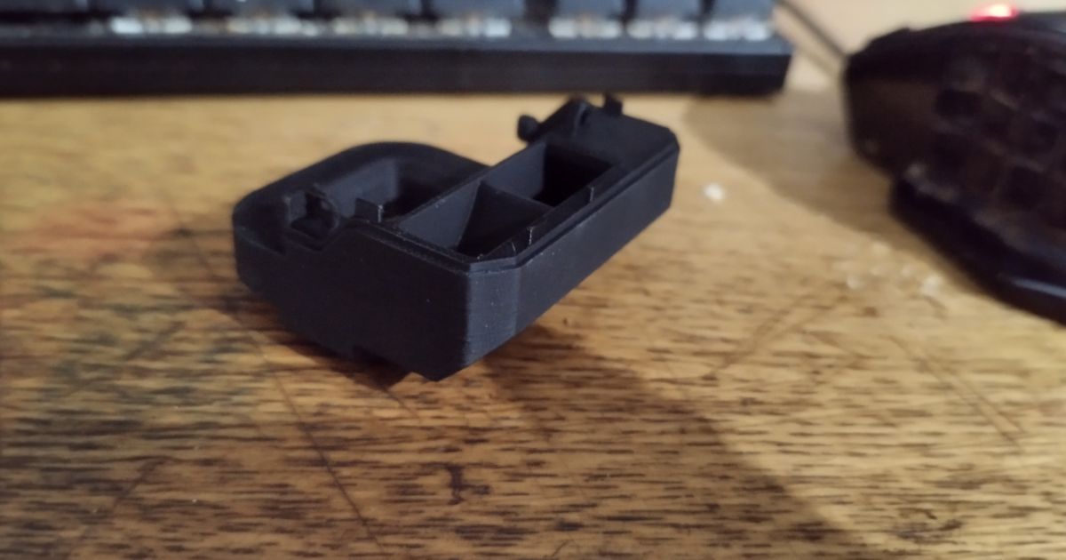
This model prints in two parts: an upper section that attaches to the toolhead, and a lower section that acts as the fan flow duct. The original fan flow duct is secured to the toolhead with 4 small screws which are somewhat redundant. This model is secured to the toolhead with 2 of these small screws, and there are holes in the top and bottom parts that allow them to be joined with the remaining 2 screws.
The original model uses magnets identical to the stock fan duct: one 2x2mm and one 4x2mm. These tiny magnets are a little annoying to source and I have hundreds of 5x1mm magnets, so I remixed the model to add pockets for 5x2mm magnets. I’m also too lazy to glue them in so I designed these pockets to be a tight fit, slide the magnets in through the top and push them into place with a screwdriver and they shouldn’t come loose.
I didn’t have an STP file for the model so I just added the pockets through booleans in Bambu studio. Adjust the dimensions of the solid blocks and negative parts to fit your desired magnets.
Note: The pockets in my 3MF file are 3mm thick. I caution against making them any thicker as I had trouble with fitting the duct to the toolhead cover when using 4mm pockets.
PRINT INSTRUCTIONS:
The part doesn’t need to be particularly strong, but it does need to be as light as possible. Its proximity to the hotend also means that some degree of heat resistance is required, which is why I recommend printing in PETG.
I recommend printing with 3 walls and 10% gyroid infill. Feel free to decrease either of these values if you would like to make the part even lighter as I have not experimented much with them.
I also recommend using normal supports for the opening of the fan duct on the lower part.
ASSEMBLY INSTRUCTIONS:
MAKE SURE TO TURN OFF YOUR PRINTER BEFORE REMOVING ANY CONNECTIONS FROM THE TOOLHEAD!
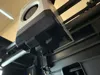
- Pull off the toolhead cover and carefully unplug the connector from the toolhead (it’s the top one).
- Unscrew the 4 screws holding the fan flow duct in place and set them to the side. These screws use the smaller hex bit (1.5?)
- The fan flow duct is secured to the toolhead cover on either side with basic plastic clips. Pinch the tops of these clips carefully with a pair of pliers or similar to disengage them and remove the flow duct.
- Take your two printed parts and align them in the shape of the final assembly with the 4 outflow ducts on the bottom.
- It’s best to work on a hard surface as you will need to apply a fair bit of pressure while you screw the parts together to make sure the screw threads properly. With the parts aligned and resting on a hard surface, take 1 of the small screws from the original fan duct and screw it into the countersunk screw hole on the top of the model. Make sure that the parts are held together tightly to avoid gaps while you do this as you want this joint to be as airtight as possible.
- Flip the model over and use another of the original small screws in the countersunk hole on the bottom to repeat the same as above.
- Once your shroud is joined with the two screws, press the your magnets into the pockets on either side of the top of the shroud. The fit is meant to be tight so they don’t fall off, so I recommend pushing them in with a screwdriver to make sure they’re snug. It would also be prudent to test the polarity of the magnets against the toolhead prior to pushing them in to make sure they are properly aligned as it would likely be difficult/impossible to remove them from the pocket without breaking the plastic.
- Carefully press the fan duct into the toolhead cover making sure to align the tabs and secure with the remaining 2 screws.