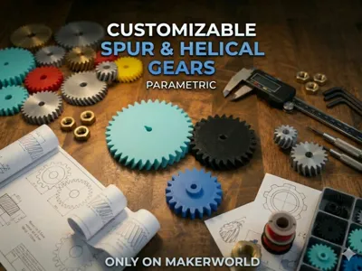
Customize Spur and Helical Gears!


Print Profile(1)

Description
Parametric Gear: Spur & Helical
A customisable 3D-printable gear. Change the tooth count, size, shaft hole, and more using configuration button near print profiles.
Parameters
Tooth size & shape
| Parameter | Default | What it does |
|---|---|---|
| module_size | 2.0 mm | Controls how big the teeth are. Think of it as tooth size in millimetres. Bigger = chunkier teeth, bigger gear. Two gears can only mesh if they share the same module_size. Common values: 1.0 (fine), 1.5, 2.0 (medium), 2.5, 3.0 (coarse). |
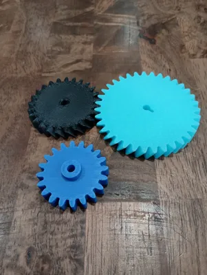
| num_teeth | 20 | How many teeth on the gear. More teeth = larger gear at the same tooth size. Fewer teeth = smaller gear, but don't go below ~12 or the tooth shape starts to deform. |
| pressure_angle | 20° | Describes the angle of the tooth's working face. 20° is the global standard and works well for 3D printing. Only change this if you're matching a specific existing gear. |
| backlash | 0.10 mm | A tiny intentional gap between meshing teeth so they don't jam. FDM printers need at least 0.05 mm. 0.10 mm is a safe all-purpose value. Increase to 0.15–0.20 if gears feel stiff after printing. |
| fillet_factor | 0.30 | Rounds the bottom corners of each tooth slot. Rounded corners are much stronger than sharp ones, sharp corners concentrate stress and crack under load. Leave this at 0.30 unless you have a specific reason to change it. |
Tooth angle (helix)
| Parameter | Default | What it does |
|---|---|---|
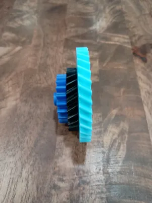
| helix_angle | 0° | At 0° the teeth run straight across the gear (a standard "spur" gear). Increasing this twists the teeth into a spiral, which makes the gear run more smoothly and quietly useful for motors or anything that needs to be quiet. 15–30° is a typical range. Note: twisted teeth push sideways on the shaft, which straight teeth don't. |
| helix_hand | "right" | Which direction the teeth spiral, left-hand or right-hand screw thread. Two meshing helical gears must use opposite hands, if one is "right" the other must be "left". Doesn't matter for straight (0°) gears. |
Size & shape of the gear body
| Parameter | Default | What it does |
|---|---|---|
| gear_height | 8 mm | How thick the gear is (measured along the shaft axis). Thicker = stronger and can handle more force, but uses more filament. A good rule of thumb is 8–15× the module_size. |
Shaft hole
| Parameter | Default | What it does |
|---|---|---|
| add_bore | true | Whether to drill a hole through the centre for a shaft. Turn off if you want a solid gear (e.g. display model or if you're gluing it). |
| shaft_diameter | 5 mm | The diameter of your actual shaft or rod. The hole is printed slightly larger than this by bore_tolerance to get the right fit. Measure your shaft with calipers before printing. |
| bore_tolerance | 0.1 mm | How much extra space is added around the shaft. 0.1 mm = tight press fit (you may need to push it on). 0.2 mm = slides on freely. Increase if your printer tends to print holes small. |
| add_hub | true | Adds a thick ring of material around the shaft hole. This stops the hole from splitting the gear when torque is applied. Recommended for anything that will actually be driven. |
| hub_diameter | 12 mm | Outer diameter of that reinforcing ring. Should be at least 2× the shaft diameter. |
| hub_height | 4 mm | How far the hub sticks out above the top face of the gear. |
| add_keyway | false | Cuts a small rectangular slot into the shaft hole. A matching metal "key" fits into this slot to lock the gear to the shaft so it can't spin freely. Useful for high-torque applications. |
| keyway_width | 2 mm | Width of the keyway slot. Match to your key size. |
| keyway_depth | 1.5 mm | How deep the keyway cuts into the bore wall. |
Render quality (safe to leave as-is for printing)
| Parameter | Default | What it does |
|---|---|---|
| TOOTH_STEPS | 24 | How many straight line segments are used to draw each curved tooth face. More segments means smoother curve. 24 is already finer than any FDM printer can reproduce. Only increase for high-res display renders. |
| FILLET_FN | 32 | How smoothly the rounded root corners are drawn. 32 is plenty for printing. Increase only for display/render purposes. |
To mesh two gears: they must share the same module_size, pressure_angle, and backlash. For helical gears also match helix_angle and use opposite helix_hand.
Axle spacing = module_size × (teeth_A + teeth_B) / 2
Example: two gears, 20 and 40 teeth, module 2.0 → axles 60 mm apart, speed ratio 2:1.
Print settings
| Material | PETG or Nylon for load-bearing use. PLA for display or light loads. |
| Infill | 40–60% for functional gears. 20% for display models. |
| Orientation | Flat on the bed, teeth pointing up. No supports needed. |
| Layer height | 0.15–0.2 mm for clean tooth surfaces. |
Suggestions for use cases
Clock or automaton: module_size 1.0, 20–60 teeth, straight teeth, minimal backlash.
Robot joint or motor drive: module_size 2.0, helix 20°, PETG, 40%+ infill, hub + keyway enabled.
Teaching model / gear ratio demo: mix different tooth counts, straight teeth, PLA fine.
Prop or costume piece: module_size 1.5–2.0, straight teeth, increase backlash to 0.15 so they mesh easily by hand.
Marble machine or wind-up toy: module_size 1.0–1.5, low tooth count, straight teeth.
Rube Golberg Machine: Go big… I mean that's what they are for right? Big fun and incredibly impractical. So do yourself a favor and max it out.
Boost Me (for free)
Want more parametric designs, let me know!
License
You shall not share, sub-license, sell, rent, host, transfer, or distribute in any way the digital or 3D printed versions of this object, nor any other derivative work of this object in its digital or physical format (including - but not limited to - remixes of this object, and hosting on other digital platforms). The objects may not be used without permission in any way whatsoever in which you charge money, or collect fees.
Comment & Rating (12)