Search models, users, collections, and posts

Smart Binary Clock (ESP32)
IP Report
Print Profile(1)

0.2mm layer, 2 walls, 15% infill
Designer
5.7 h
3 plates
Open in Bambu Studio
Boost
3
7
1
0
4
3
Released
Bill of Materials
List other parts
- ESP32 Development Board x 1: The main microcontroller with Wi-Fi for NTP sync
- White LEDs 5mm x 17: 17 LEDs are required for the 3-column binary display
- 1K Ohm Resistors x 17: Essential for protecting each LED from overcurrent
- 74HC595 Shift Register x 3: Used to drive the 17 LEDs using only 3 data pins.
- DS3231 RTC Module x 1: Provides high-precision hardware time backup
- Universal Perf-board x 1: For mounting and soldering all the electronic components
- Hook-up Wire (30 AWG recommended) x 1: For internal wiring between the controller and LEDs.
- USB Cable (Micro-USB or USB-C) x 1: For power supply and programming the ESP32
Description
Smart Binary Clock (ESP32)
Overview
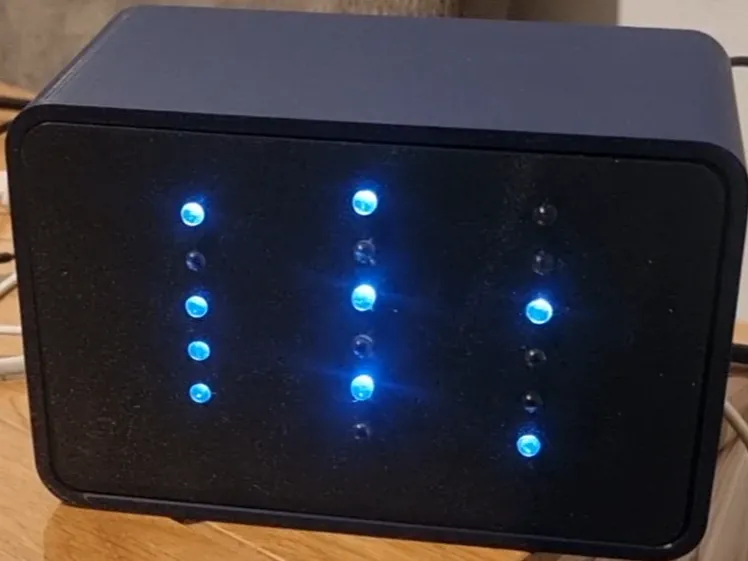
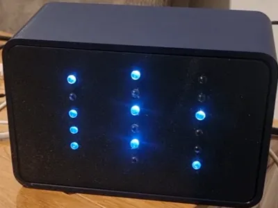
This is a sleek, 3D-printed binary clock powered by an ESP32 microcontroller. It combines modern technology with a minimalist aesthetic, making it a perfect "geeky" conversation piece for any desk or office.
Key Features
- NTP Synchronization: The clock automatically fetches precise time over Wi-Fi, ensuring it's always accurate without manual adjustments.
- RTC Hardware Backup: Includes support for a DS3231 module to maintain time during power outages or when Wi-Fi is unavailable.
- Efficient LED Driving: Controls 17 LEDs using only 3 data pins through a daisy-chain of shift registers.
- Optimized for Bambu Lab A1: The enclosure is specifically designed for high-quality results on the Bambu Lab A1 printer.
How to Read the Time
The LEDs are organized into three vertical columns: Hours (Left), Minutes (Center), and Seconds (Right). Each row represents a binary bit value (from bottom to top):
- Row 1: 1
- Row 2: 2
- Row 3: 4
- Row 4: 8
- Row 5 (Hours Only): 16
Simply sum the values of the lit LEDs in each column to read the current time.
Bill of Materials (BOM)
- Microcontroller: 1x ESP32 Development Board (e.g., ESP32 DevKit V1).
- Display: 17x Blue LEDs (5mm or 3mm).
- Resistors: 17x 1K Ohm resistors (one for each LED to ensure stable current).
- Logic: 3x 74HC595 Shift Registers (daisy-chained).
- Timekeeping: 1x DS3231 RTC Module for high-precision hardware backup.
- Power: 1x USB Cable (Micro-USB or USB-C, depending on your ESP32 board).
- Prototyping: 1x Perf-board or custom PCB, plus jumper wires for connections.
Source Code & Documentation
The full source code with detailed English comments and license info is available on my GitHub repository: https://github.com/yossiRav/Smart-Binary-Clock
Documentation (1)
Assembly Guide (1)
binary_clock_wiring.pdf
License

This user content is licensed under a
Creative Commons Attribution-Noncommercial


Comment & Rating (1)