AMS Hub using A1 AMS Lite Hub - Buffer Housing


Print Profile(2)


Description
BACKGROUND
This is a remix to other buffer housings that incorporates the A1/A1 Mini AMS Lite Hub to let you connect 4 AMS's without having to purchase the AMS Hub. The AMS Lite hub has a more desirable filament path compared to the AMS hub. I decided to re-draw this from scratch as others have mentioned issues of spring alignment and I also wanted to make several other changes.
- Optimized design to eliminate supports and minimize bridging
- Re-designed spring retainment section & ensured proper alignment
- Removed threads from posts and sized pilot hole properly for the Bambu thread forming screws
- Re-designed cable clip
- Added sliding mechanism guide ribs
- Added support ribs for circuit board
- Added the alignment tab to the bottom of the buffer
- Designed the AMS Lite Hub retaining section with an open side for easier removal and minimize bridging
- Added a retaining clip to keep the AMS Lite Hub from accidentally backing out of the PTFE fitting
- Designed to “nominal” dimensions vs. as measured dimensions
- Added step-by-step walkthrough
PARTS LIST
QTY: 1 - AMS Lite Filament Hub (Select Your Region)
US - https://us.store.bambulab.com/products/ams-lite-filament-hub?_pos=2&_sid=6cd43978e&_ss=r
EU - https://eu.store.bambulab.com/products/ams-lite-filament-hub?skr=yes&_pos=2&_sid=6cd43978e&_ss=r
UK - https://uk.store.bambulab.com/products/ams-lite-filament-hub?skr=yes&_pos=2&_sid=6cd43978e&_ss=r
AU - https://au.store.bambulab.com/products/ams-lite-filament-hub?skr=yes&_pos=2&_sid=6cd43978e&_ss=r
CA - https://ca.store.bambulab.com/products/ams-lite-filament-hub?skr=yes&_pos=2&_sid=6cd43978e&_ss=r
JP - https://jp.store.bambulab.com/products/ams-lite-filament-hub?skr=yes&_pos=2&_sid=6cd43978e&_ss=r
GLOBAL - https://store.bambulab.com/products/ams-lite-filament-hub?skr=yes&_pos=2&_sid=6cd43978e&_ss=r
INSTALLATION
TOOLS REQUIRED
- H1.5 Hex Key
- H2.0 Hex Key
- Micro Flush Cutters or Utility Knife
DISASSEMBLY
1) Removed the spring from the buffer. I find it easiest to insert your H1.5 hex key and pry the spring backwards so it releases from the plastic housing.

2) Remove the upper PTFE coupler retaining cap by removing the QTY: 2 - 2mm screws using your H1.5 hex key.

3) Remove the PTFE coupler from the lower retaining housing. Then remove the lower retaining housing and PTFE slider from the buffer housing. I found it easiest to evenly pry the lower retaining housing from underneath through the 12mm hole on the side of the buffer housing.

4) Remove the circuit board from the buffer housing by removing the QTY: 3 - 2mm screws using the H1.5 hex key

ASSEMBLY
1) (Optional) I found it easier to pre-tap the thread by threading one of the forming screws approximately 4mm into the posts. There are a QTY: 5 of these posts that can be pre-tapped. Extreme care must be taken on the QTY: 2 tall posts as they are more fragile.

2) Secure the circuit board into the printed housing by screwing in the QTY: 3 - 2mm screws using the H1.5 hex key.
NOTE: These screws are thread forming screws so they will feel a bit snug the first time they are secured into the housing. Ensure the screws are concentric with the posts as you tighten. Do NOT overtighten the screws.

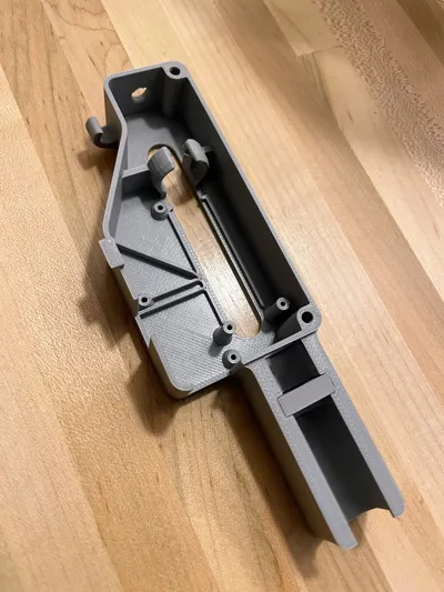
3) Insert the lower PTFE retaining housing and sliding PTFE housing into the printed housing. Depending on your print settings and quality, the fit may be tight. Evenly apply pressure to both post sections until the housing bottoms out ensuring the alignment legs on the bottom of the sliding mechanism are between the guide tabs on the print, otherwise the sliding mechanism will not sit level or function correctly.

4) Place the PTFE coupler in the lower housing and then place the upper retaining housing and attach to the printed frame using the QTY: 2 - 2mm screws using the H1.5 hex key.
NOTE: These screws are thread forming screws so they will feel a bit snug the first time they are secured into the housing. Ensure screws are concentric with the posts as you tighten. Do NOT overtighten the screws. If alignment is improper or too much torque is applied, you run the risk of snapping off the posts.


5) Install the spring back into the housing. I find it easiest to slide the spring over the PTFE fitting of the sliding mechanism, compress and then guide it into the printed housing.

6) You need to remove the magnet from the AMS Lite Hub. This is easily accomplished using micro flush cutters and probably have them on hand if you use them to trim filament.


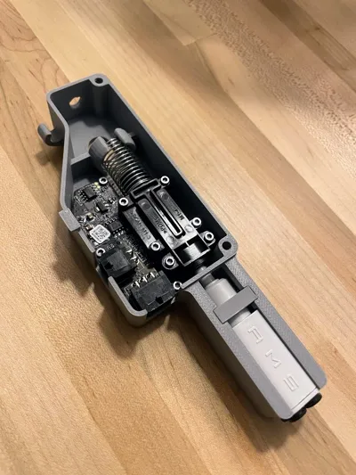
7) Insert the AMS Lite Hub into the buffer assembly (AMS label up as shown) and push until the buffer bottoms out in the housing. There is a counterbore in the housing so the hub will bottom out and prevent over insertion. While pushing the hub inward, take your locking clip and push it into it's respective slot. It will snap into place over the round portion of the hub and prevent accidental release from the PTFE fitting. The PTFE fitting is designed for 4mm OD tubing and the hub nipple is 4.5mm OD so it only press-fit into place and does not actually engage the metal locking teeth. If you ever need to remove the AMS Lite hub, a pair of needle nose pliers can be used to remove the printed locking clip.

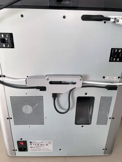
8) Attach buffer to back of printer using the original QTY: 2 - 3mm screws using your H2.0 hex key. You will need to break through the sacrificial bridged section of the counterbores before you can insert the screws. Re-connect cables, ensuring to use cable clip to keep it out of the way of the purge chute. Attach AMS PTFE tubes to the AMS Lite Hub.

This remix is based on


Comment & Rating (148)