
Compact Split AMS Lite Riser
Print Profile(2)


Description
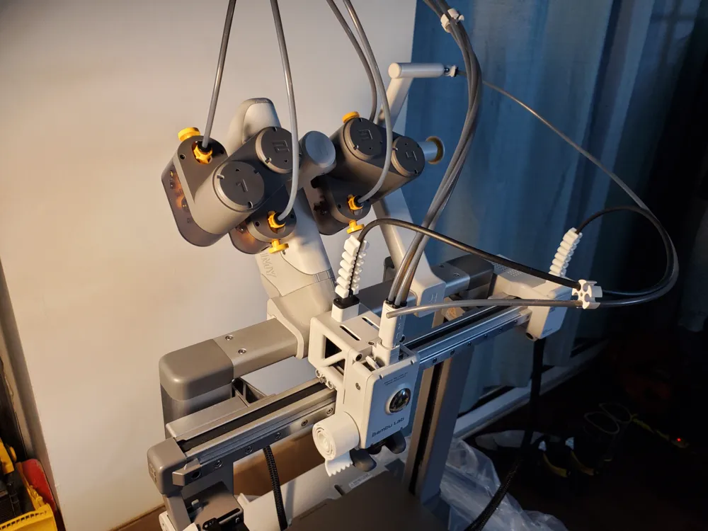
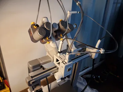
The original AMS Lite proved too bulky and cumbersome for my liking. I explored numerous solutions for mounting a disassembled AMS Lite to the A1 printer's crossbeam, but none fully satisfied my requirements. I therefore embarked on a completely new design, incorporating my own design philosophy and inspiration from others. My design prioritizes compactness, robustness, affordability, ease of printing, and maximal reuse of original AMS components. As I currently lack the capability to fabricate wiring harnesses, I haven't included provisions for the filament spool RFID tag coil signal lines. However, adding these should be straightforward using a drill to create cable entry holes in the housing at a later stage.
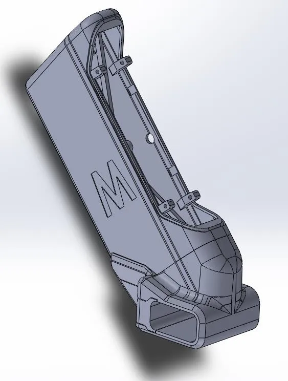
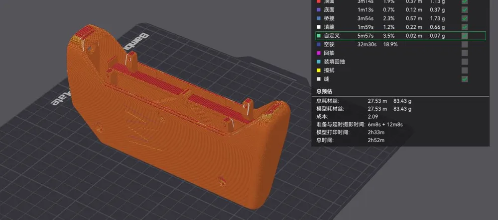
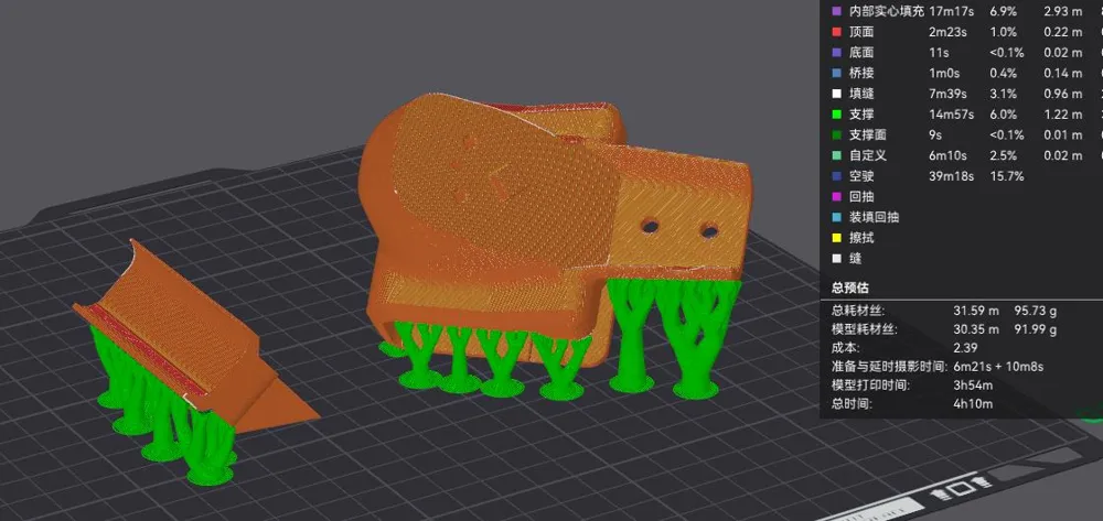
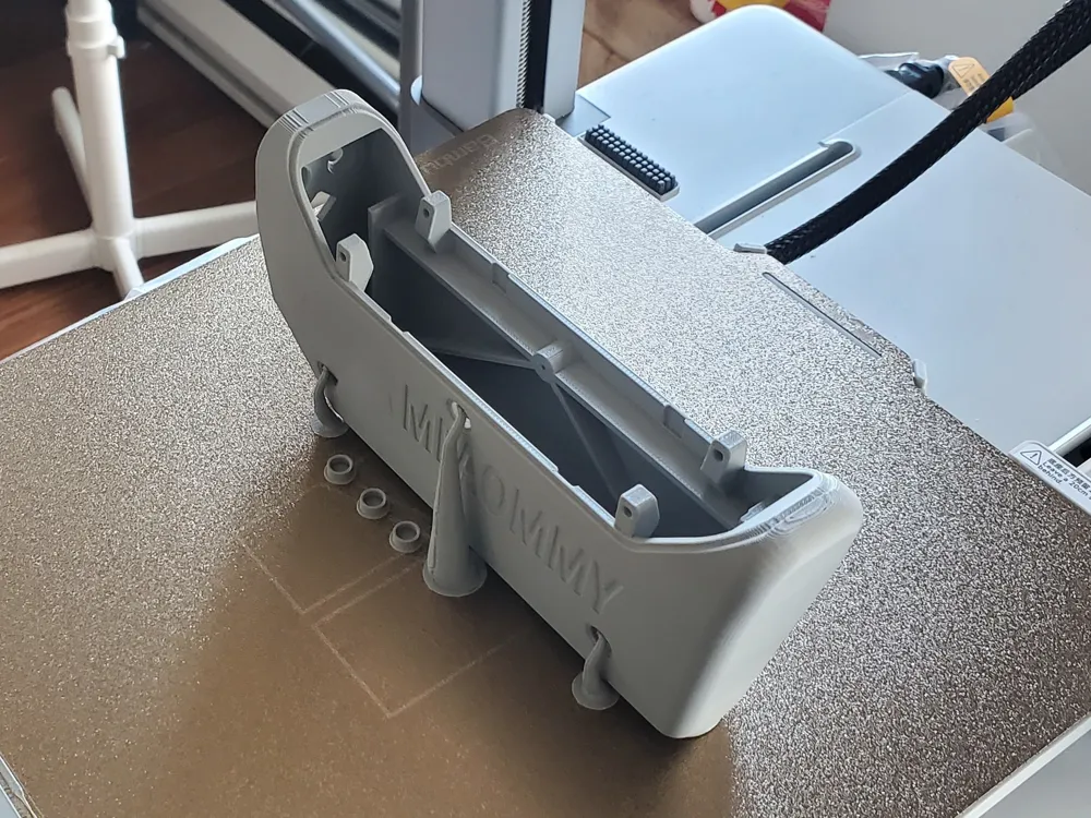
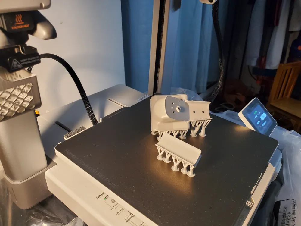
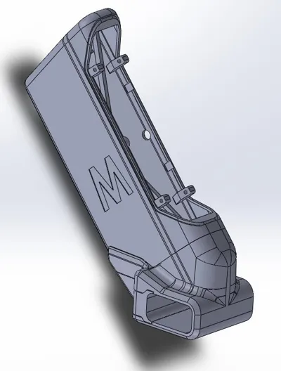
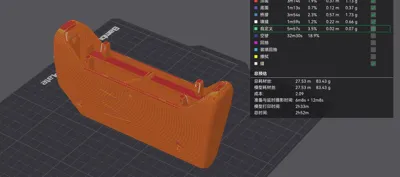
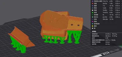
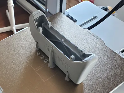
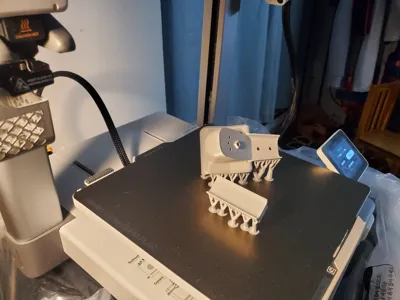
Due to differing print configurations for the housing and base, the project is split into two print configurations. The first comprises the housing for the feeder and mainboard. The second contains the base for crossbeam mounting.
Project Components: Only four 8 x 1-¼ inch pan head wood screws and four 8 x 5/8 inch countersunk wood screws need to be purchased separately. All other parts are reused from the disassembled AMS unit.
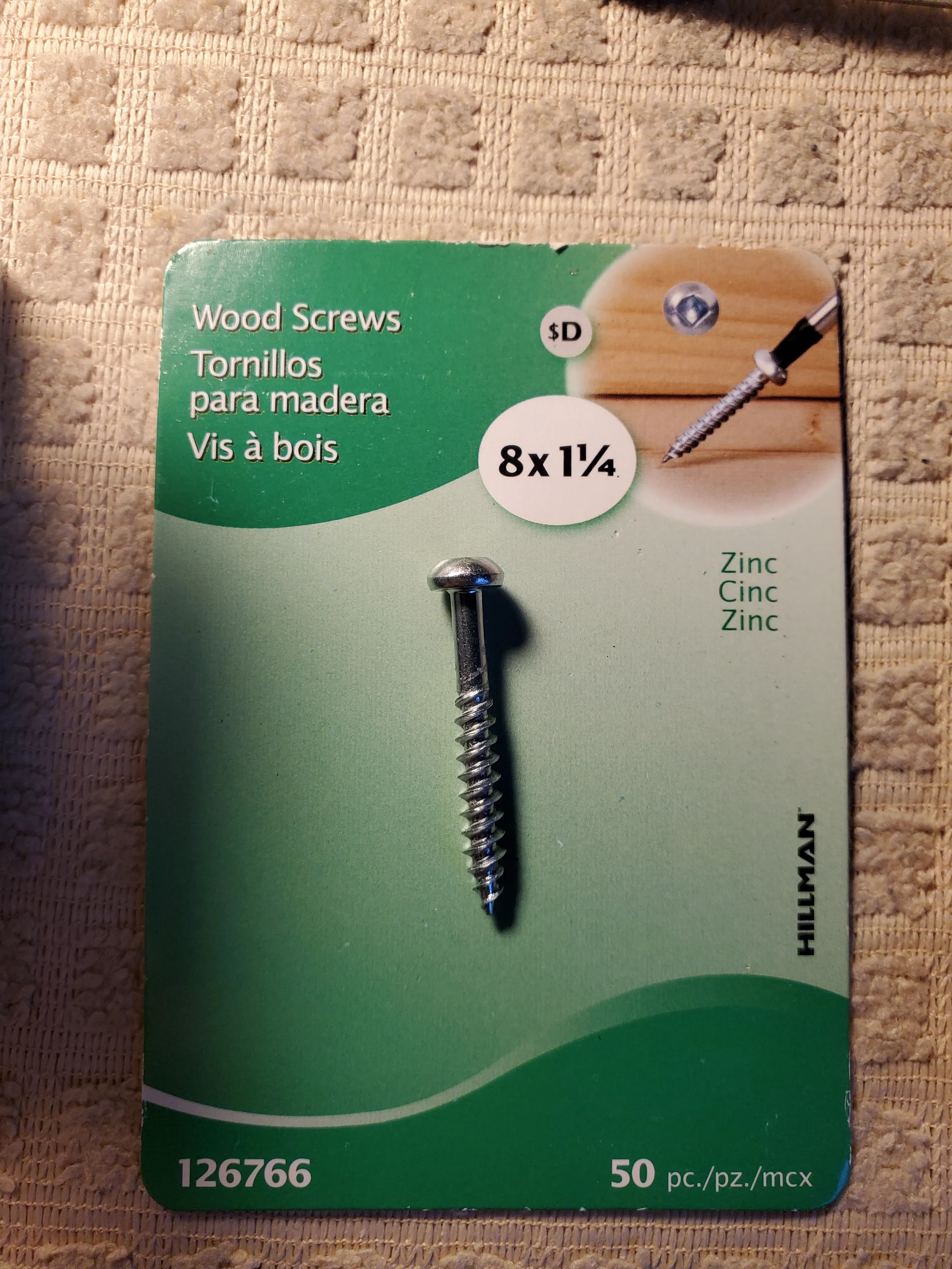
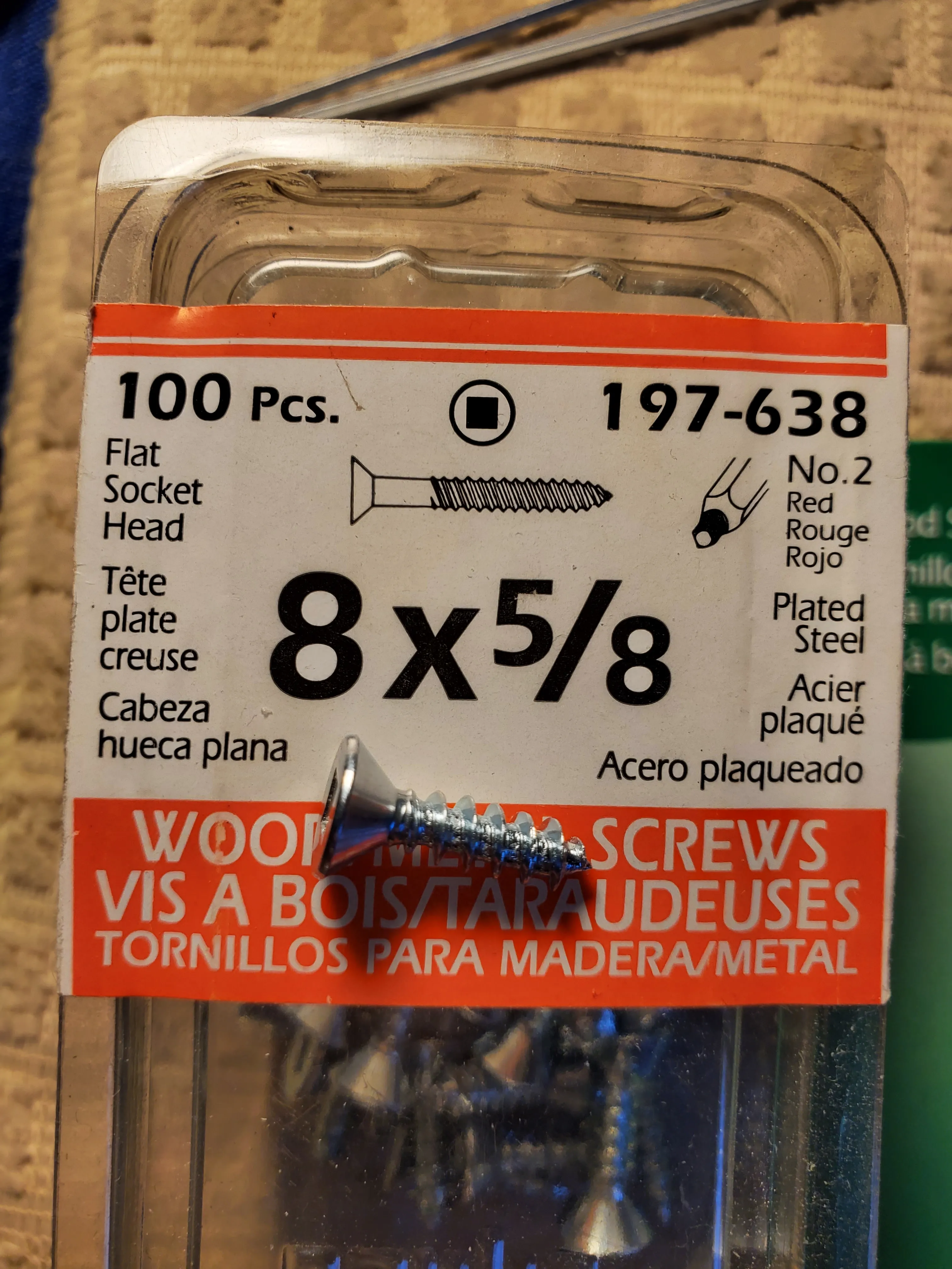
Assembly Instructions:
1. Disassemble the AMS. Remove the feeder and the connecting housing in one piece.
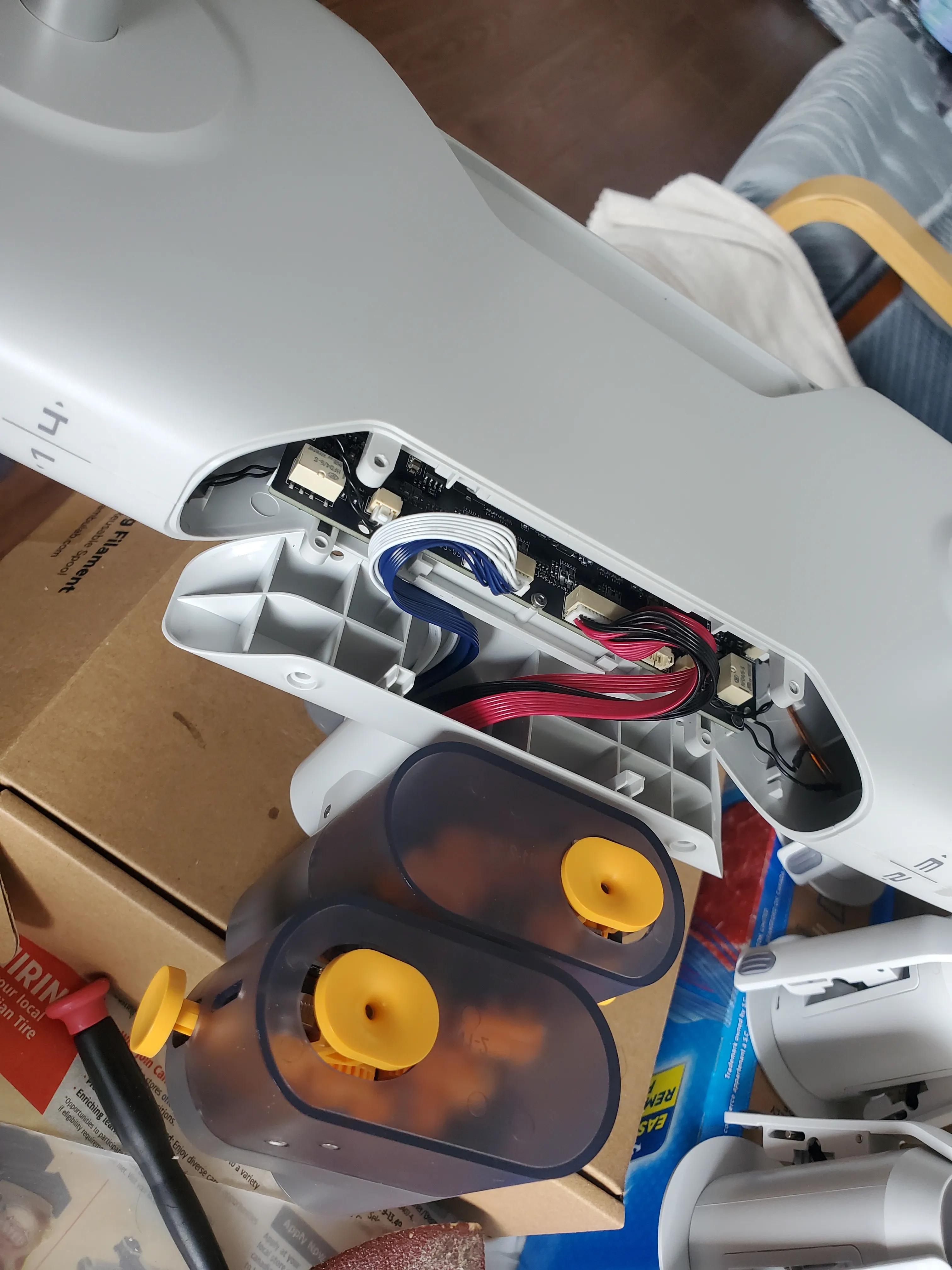
2. Disconnect the wiring harness and remove the main circuit board.
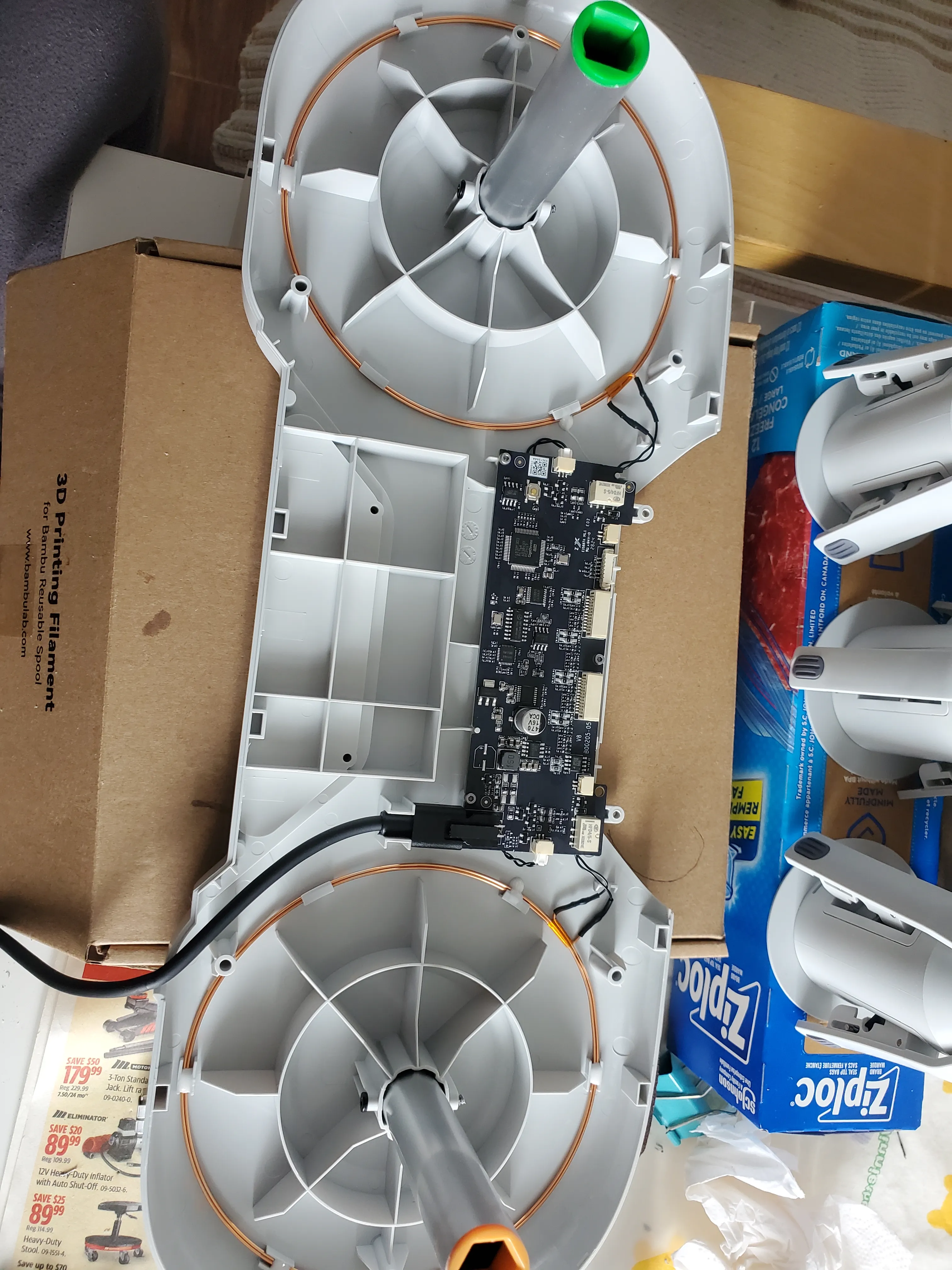
3. Use a 7/64 drill bit to deburr the screw mounting holes.
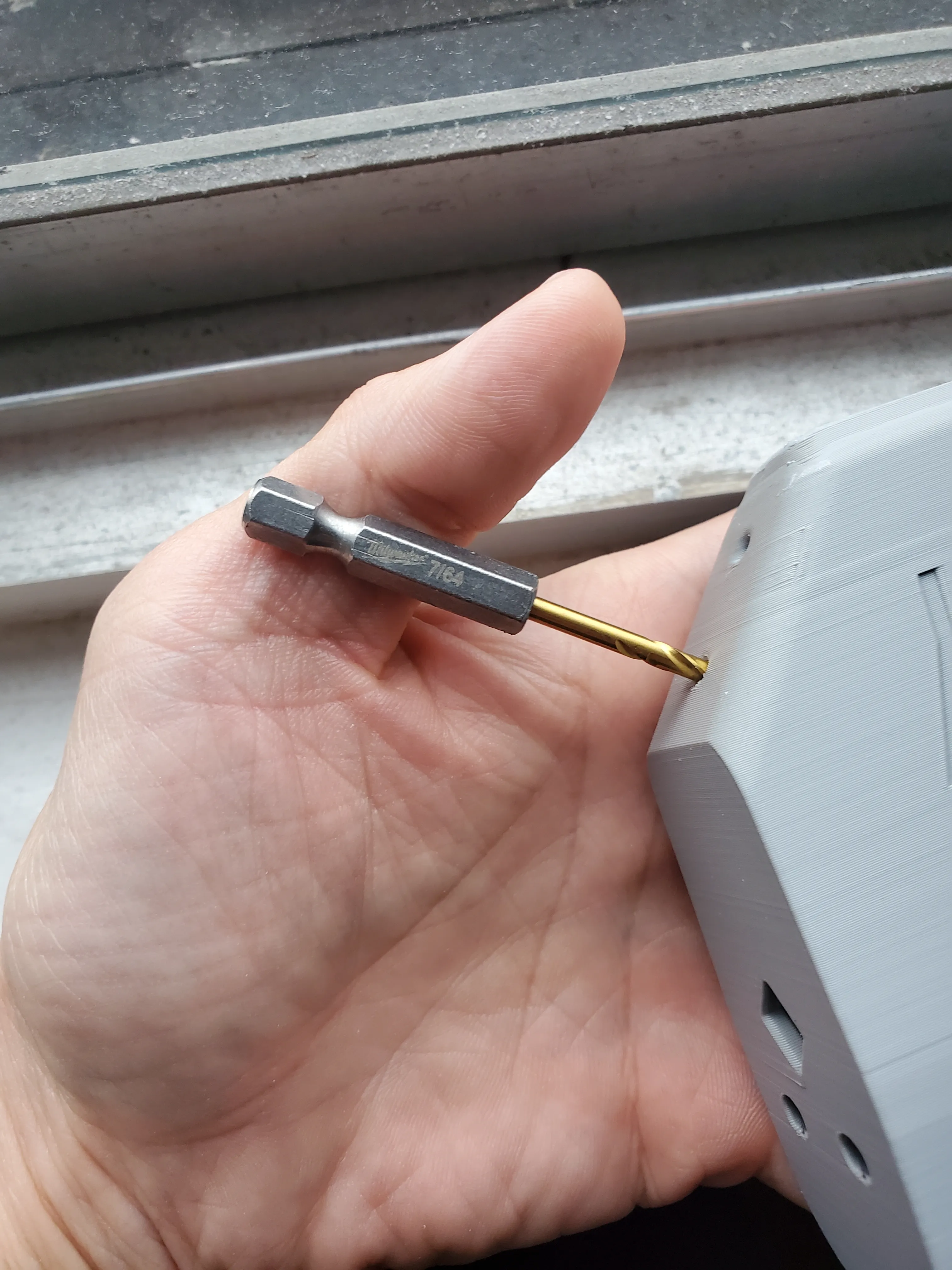
4. Connect the base and housing.
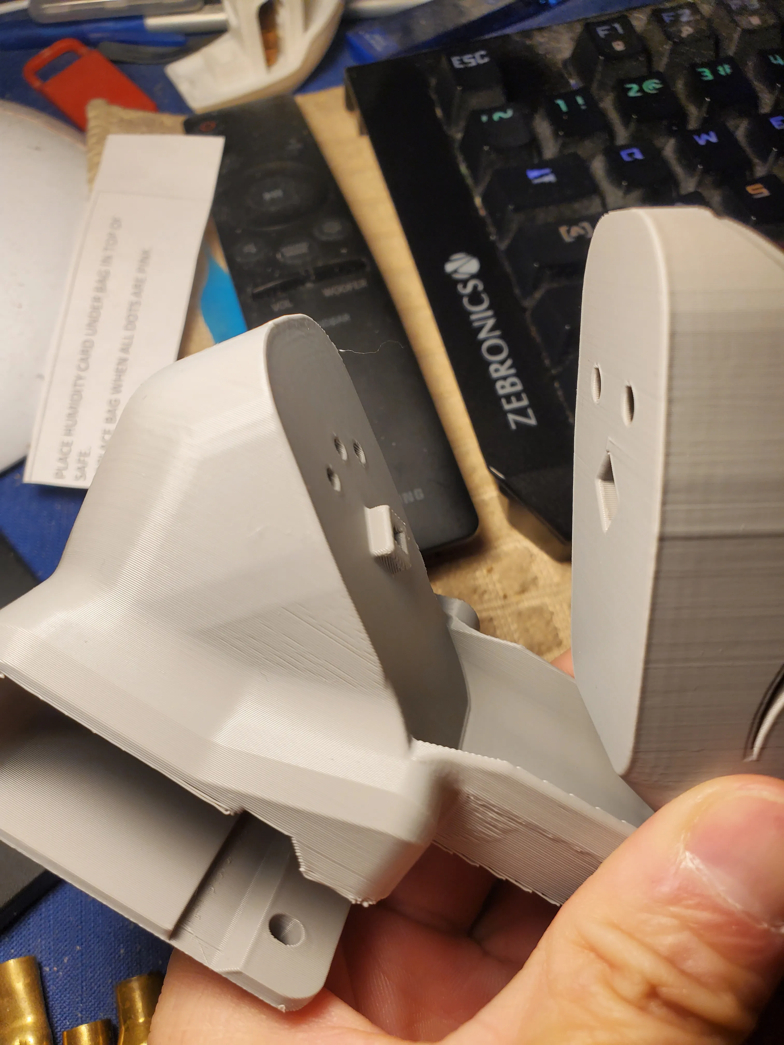
5. Secure the base and housing using four 8 x 5/8 inch countersunk wood screws.
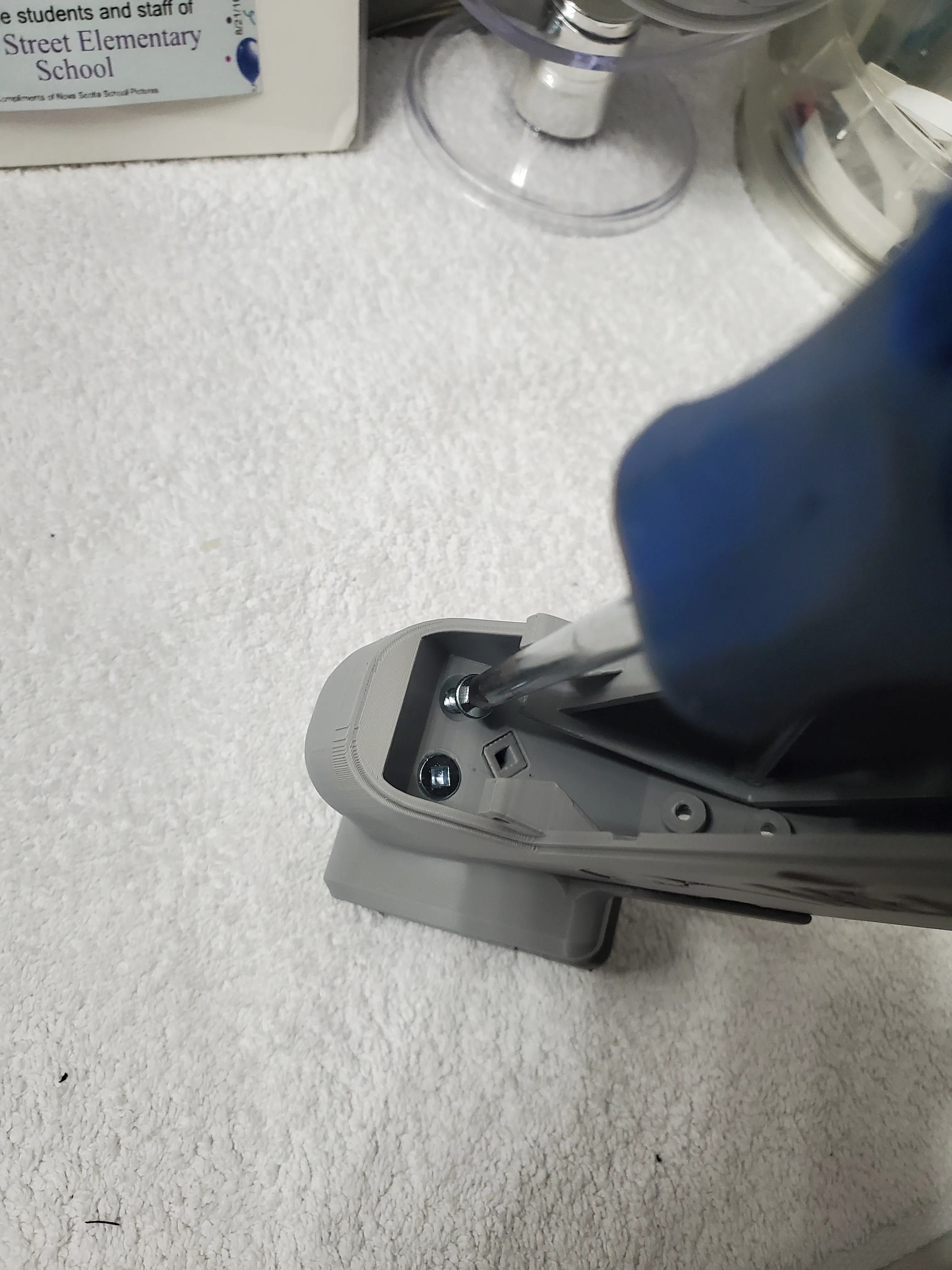
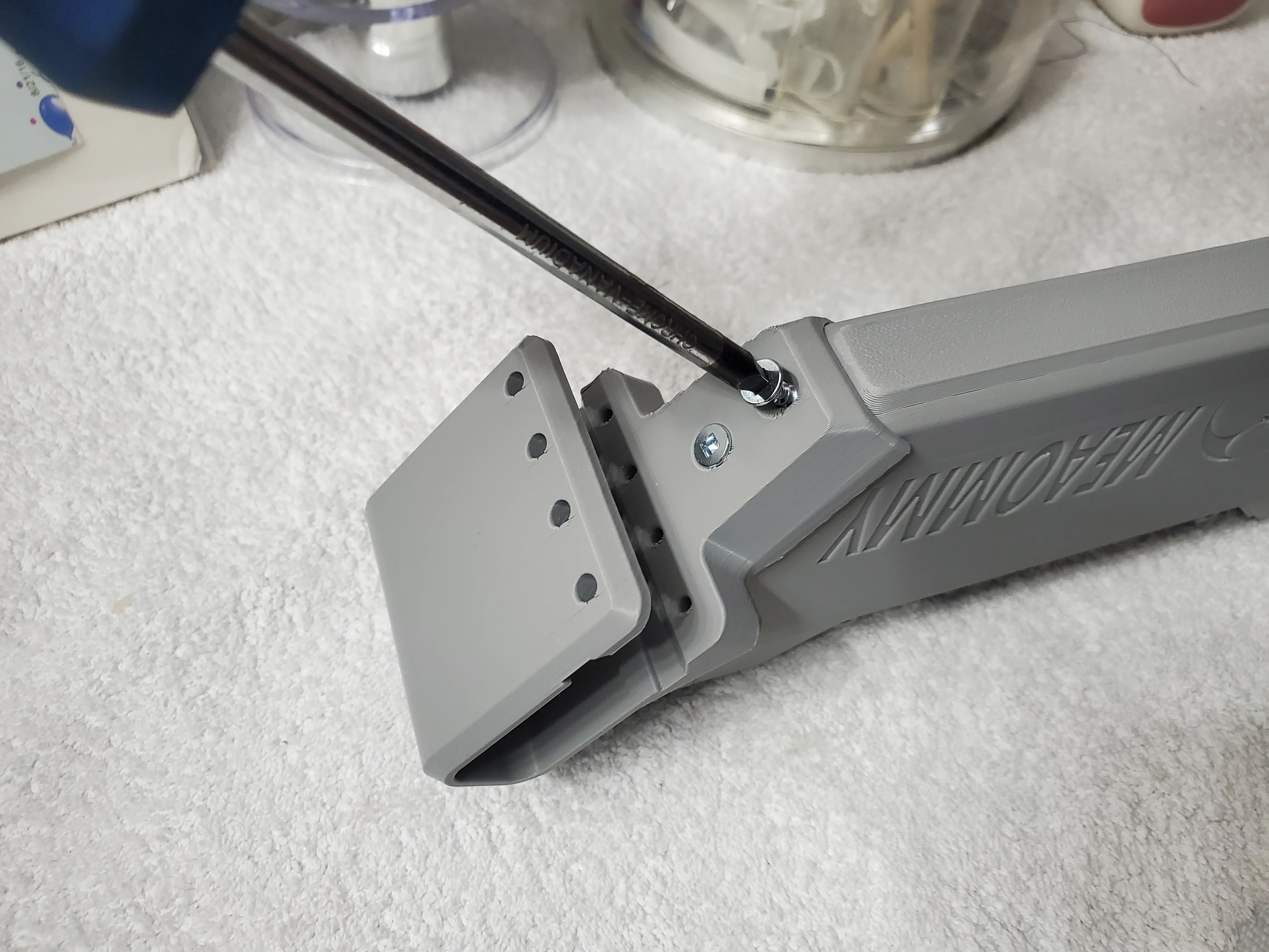
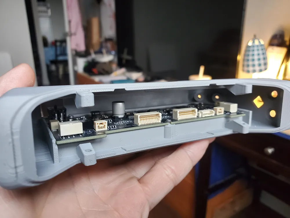
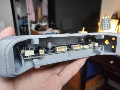
6. Insert the circuit board into the housing and check the screw hole alignment.
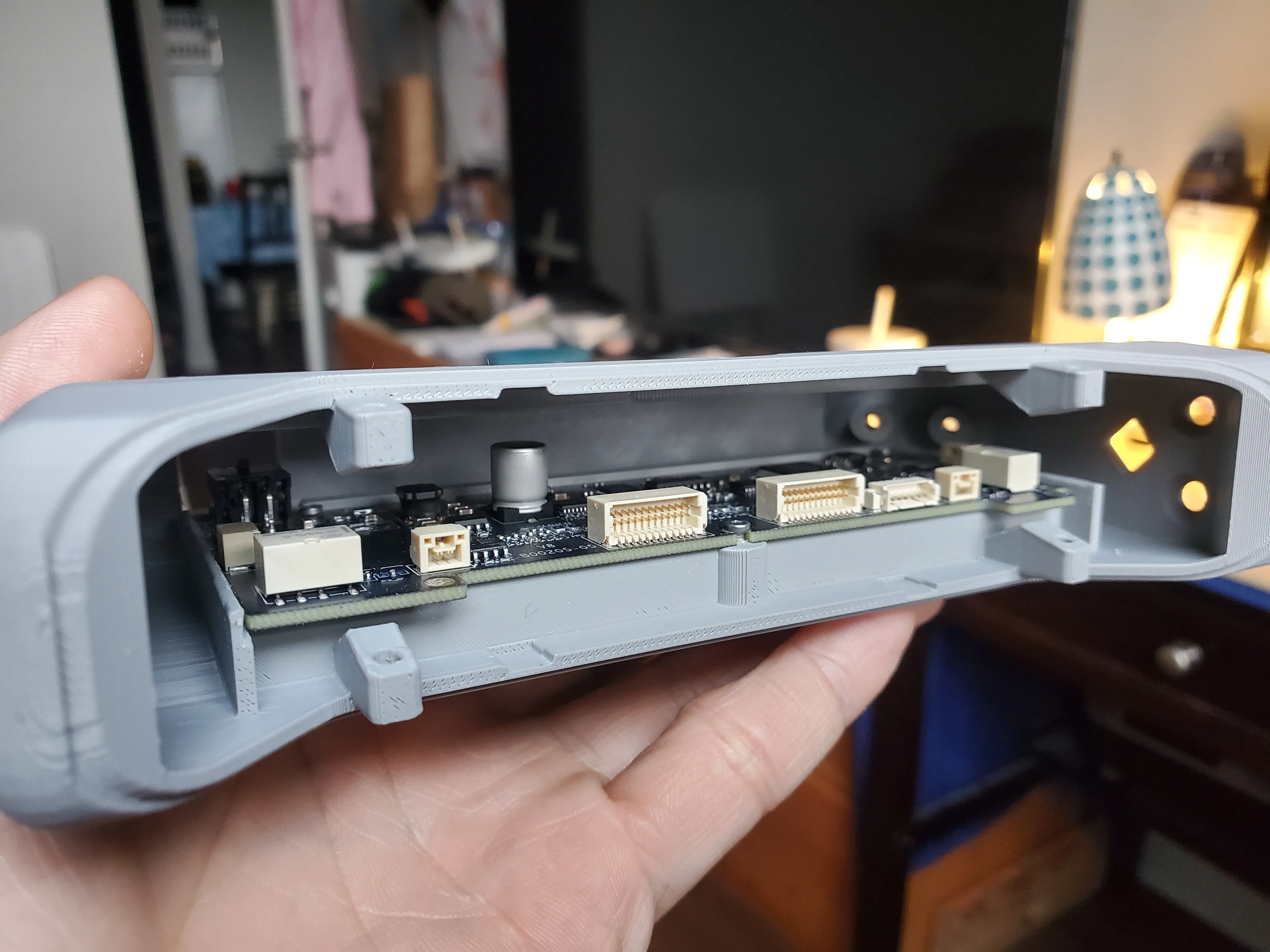
7. Using the mounting screws from the disassembled AMS circuit board, attach the board to the housing. Tighten the screws using a hex key inserted through the top access hole. Exercise caution to avoid over-tightening and damaging the screw holes in the housing.
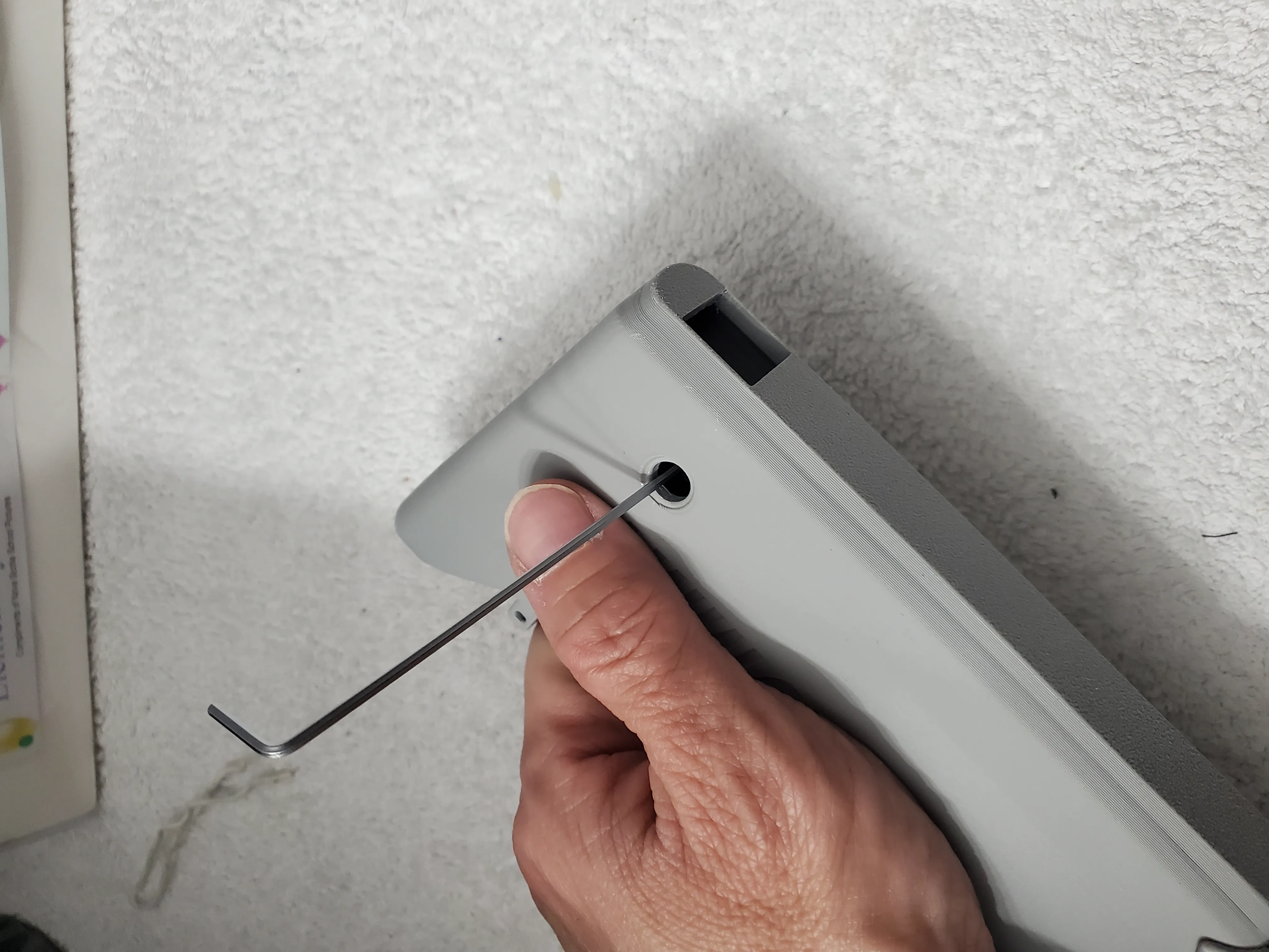
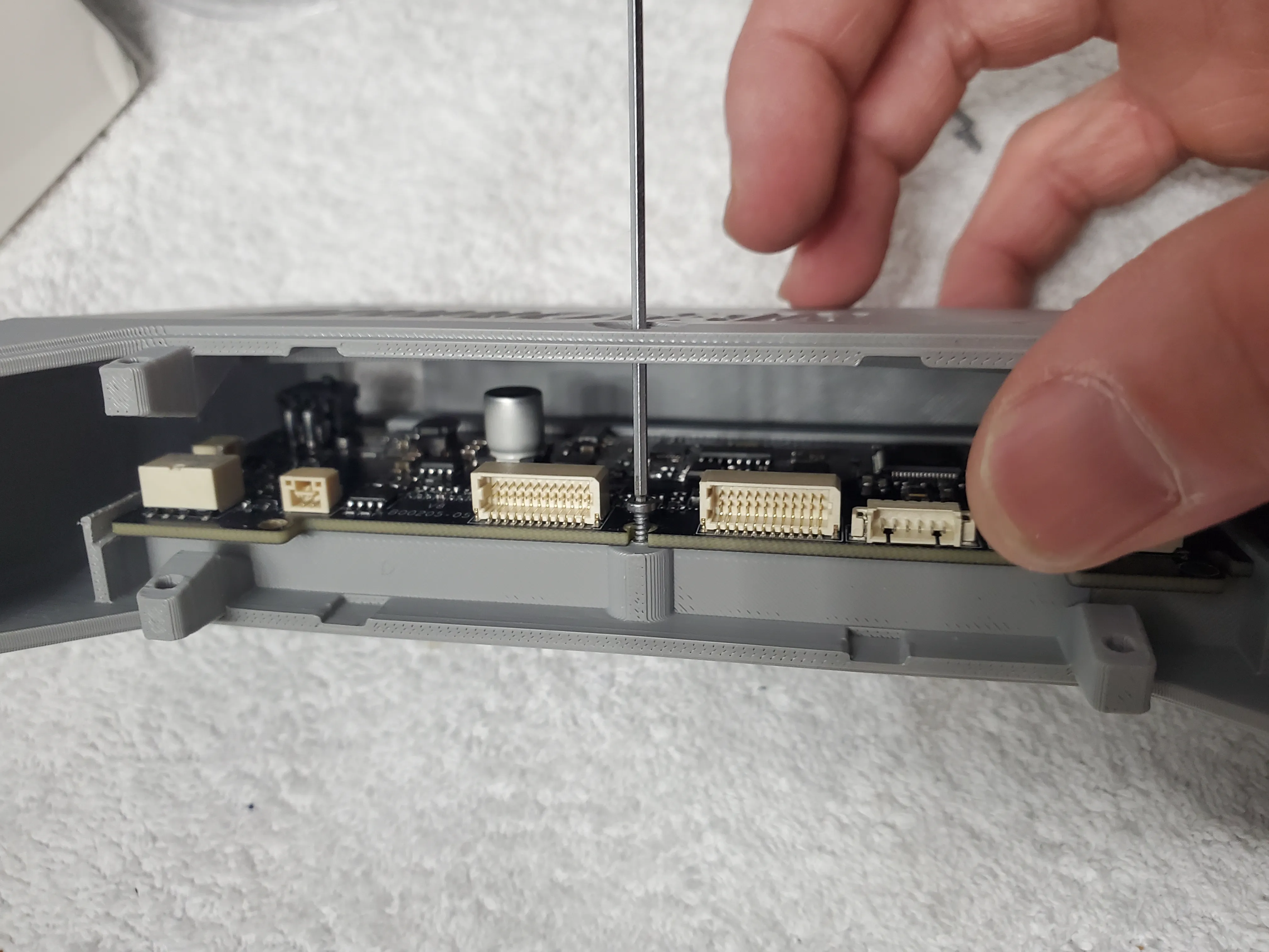
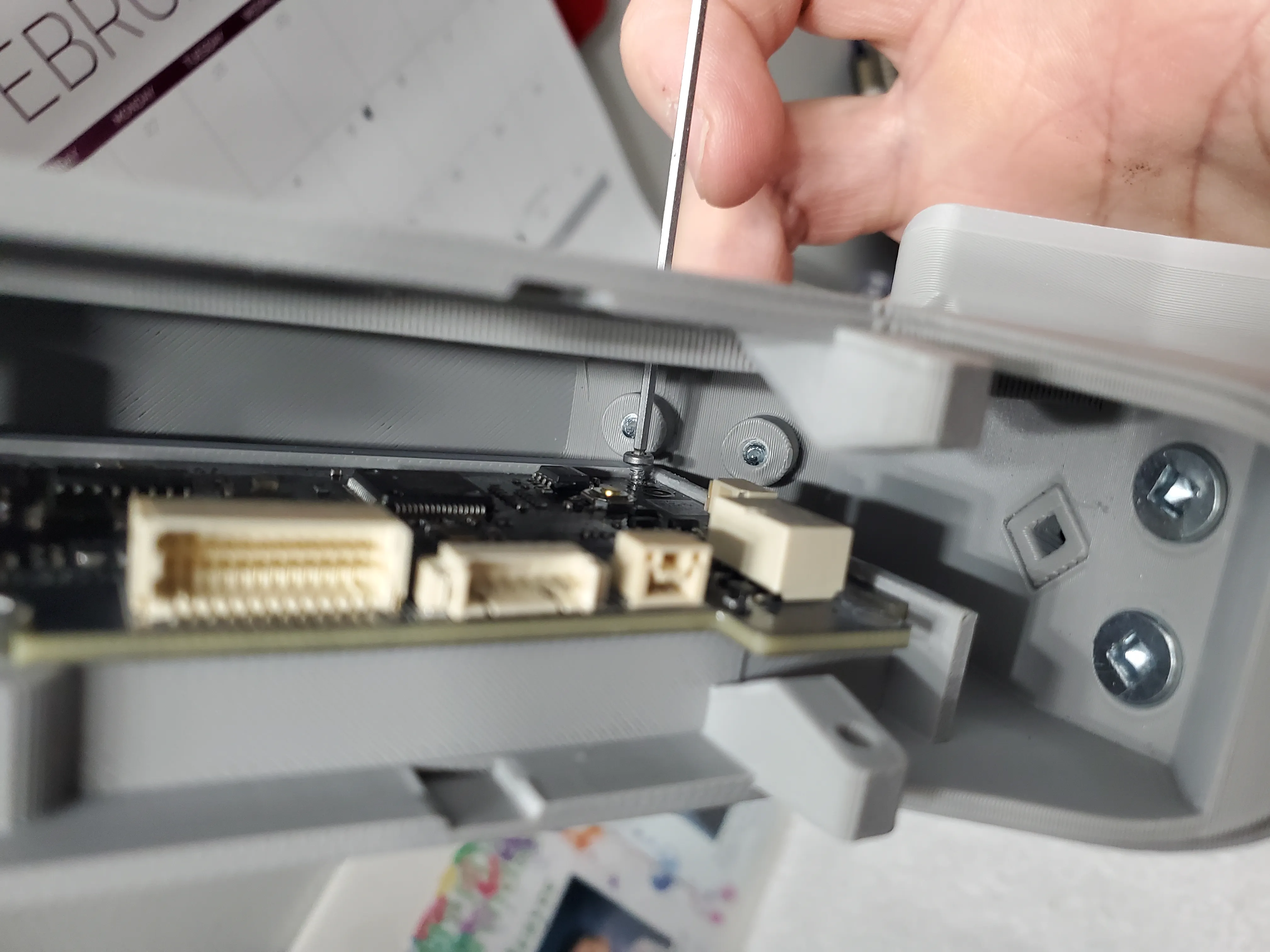
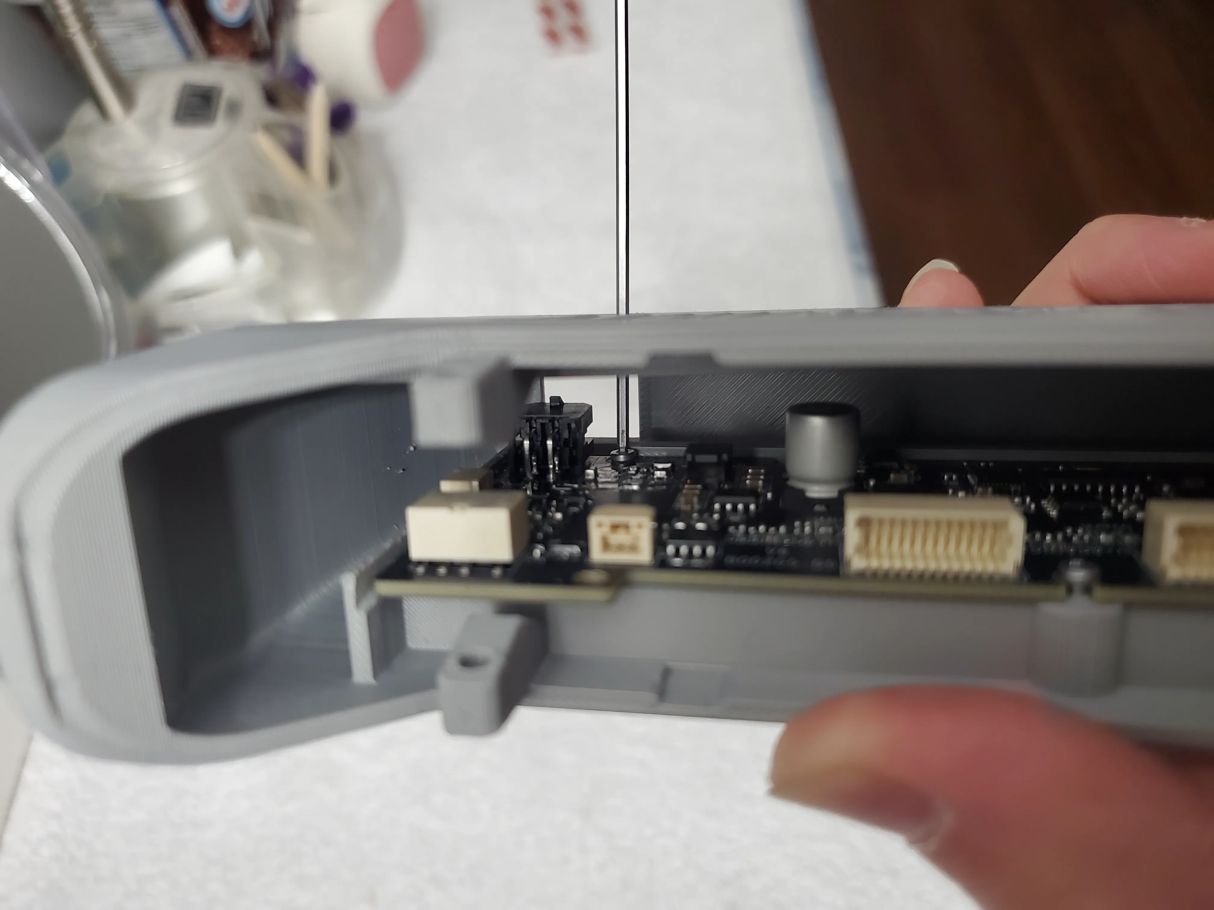
8. Use the larger dust cap from A1 Base Hole Caps by Bogdy0404 - MakerWorld to cover the access hole.
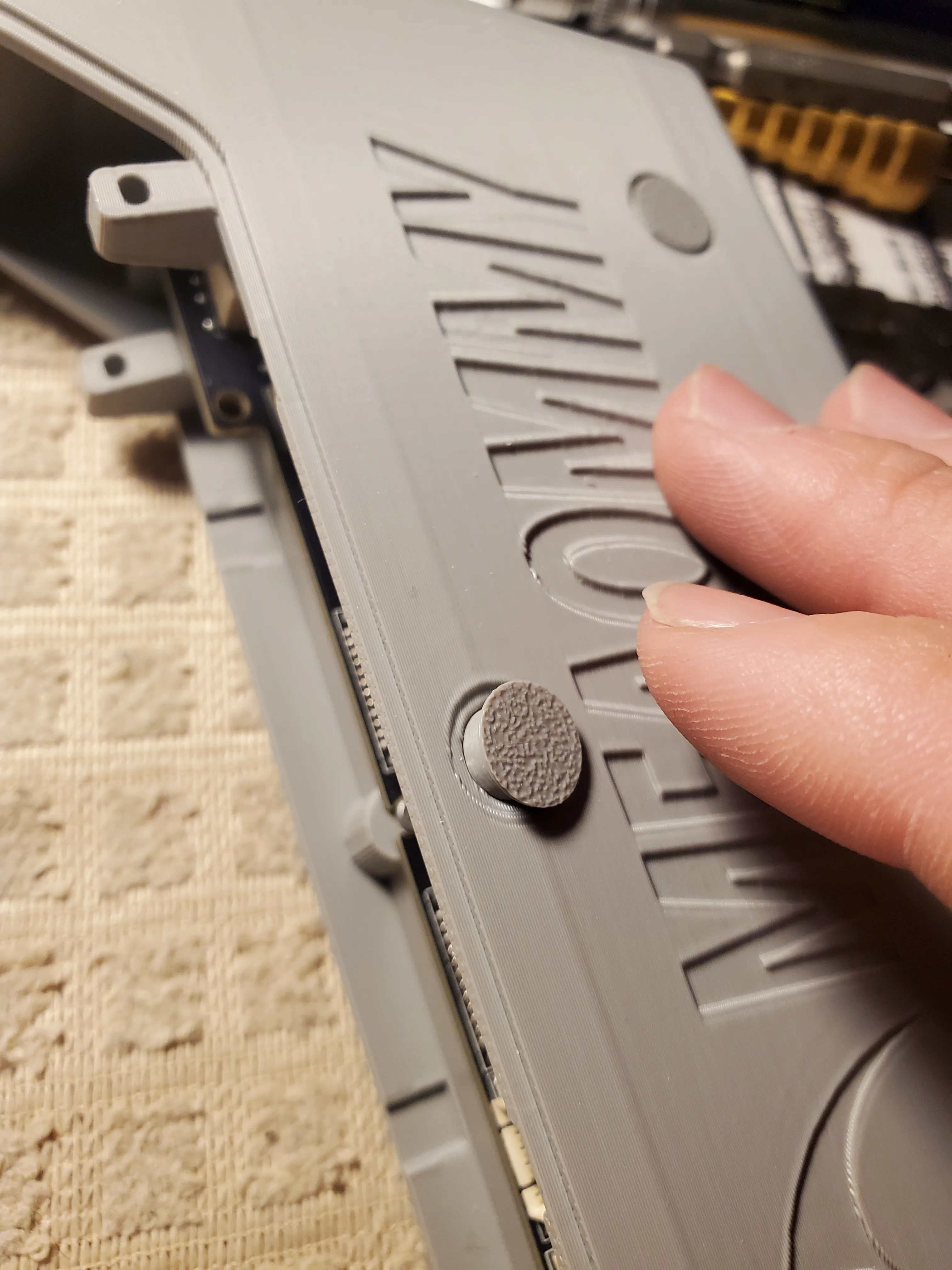
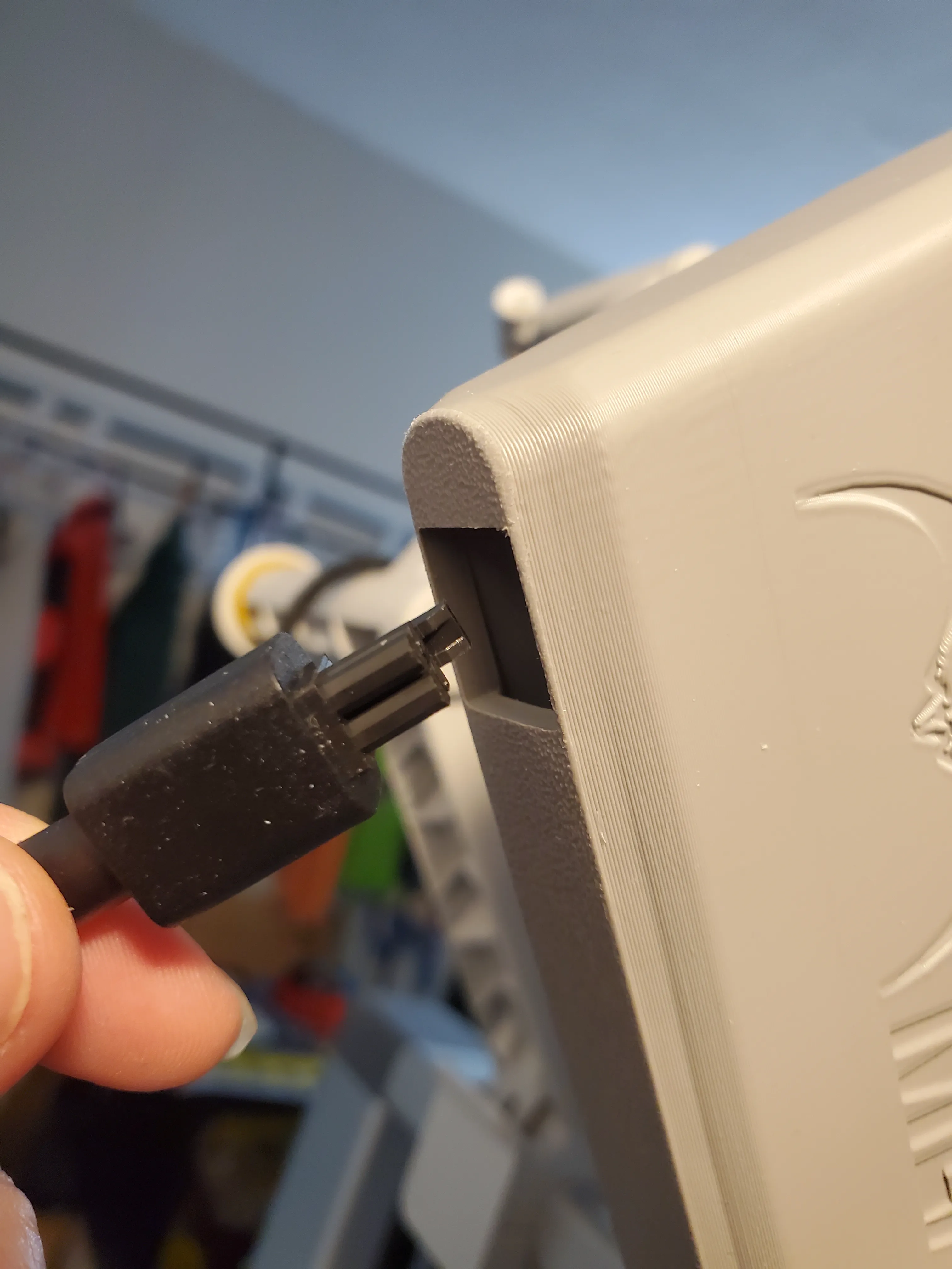
9. Connect the feeder cable to the mainboard. Ensure correct connection.
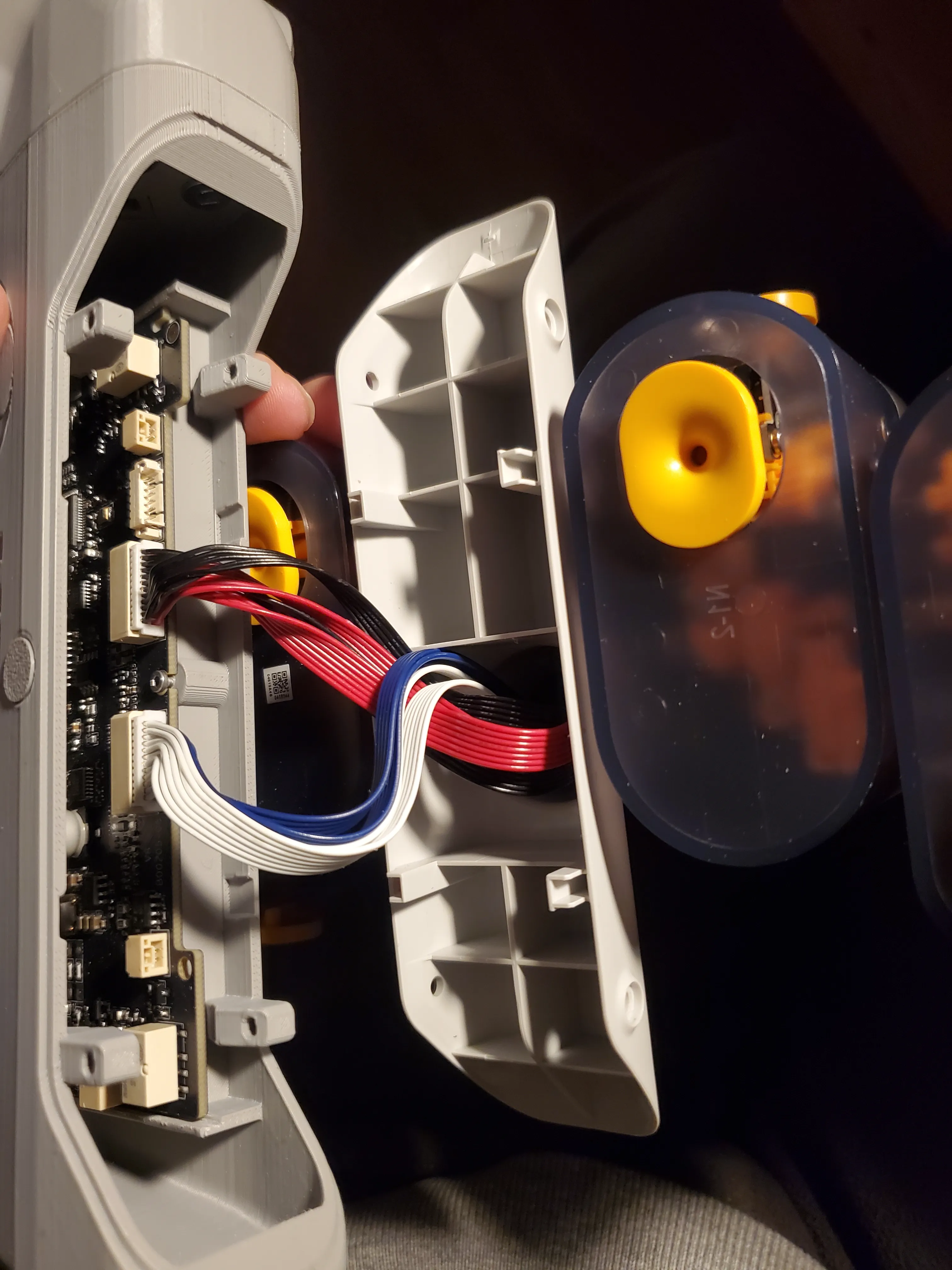
10. Mount the feeder to the housing using the screws from the disassembled AMS unit. Pay attention to orientation, ensuring that the numbers “1, 2, 3, 4” on the feeder are upright.
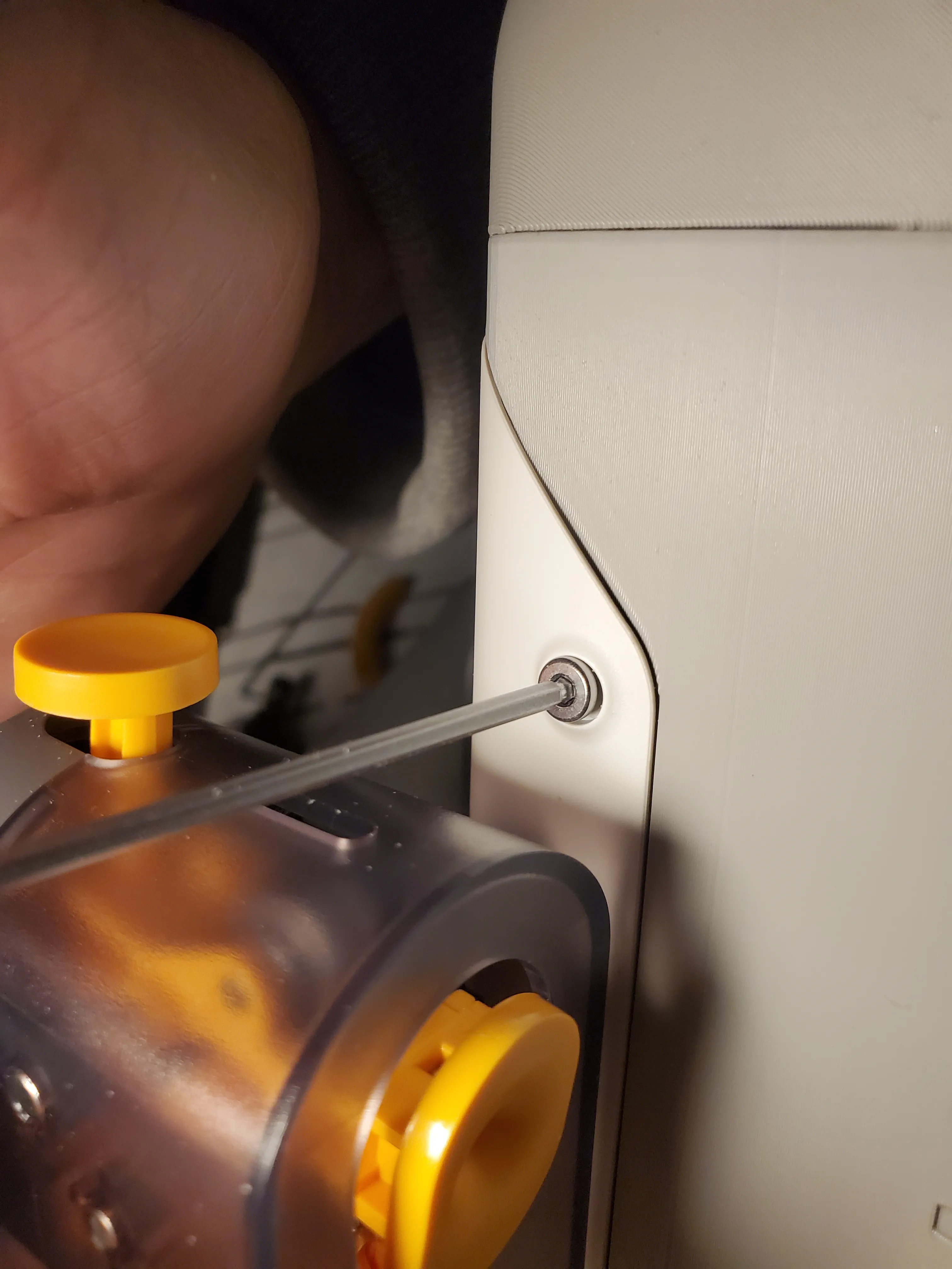
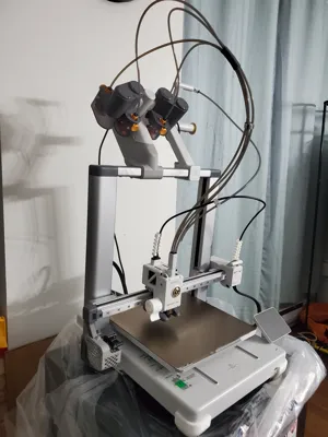
11. Insert the AMS assembly into the crossbeam via the base opening.
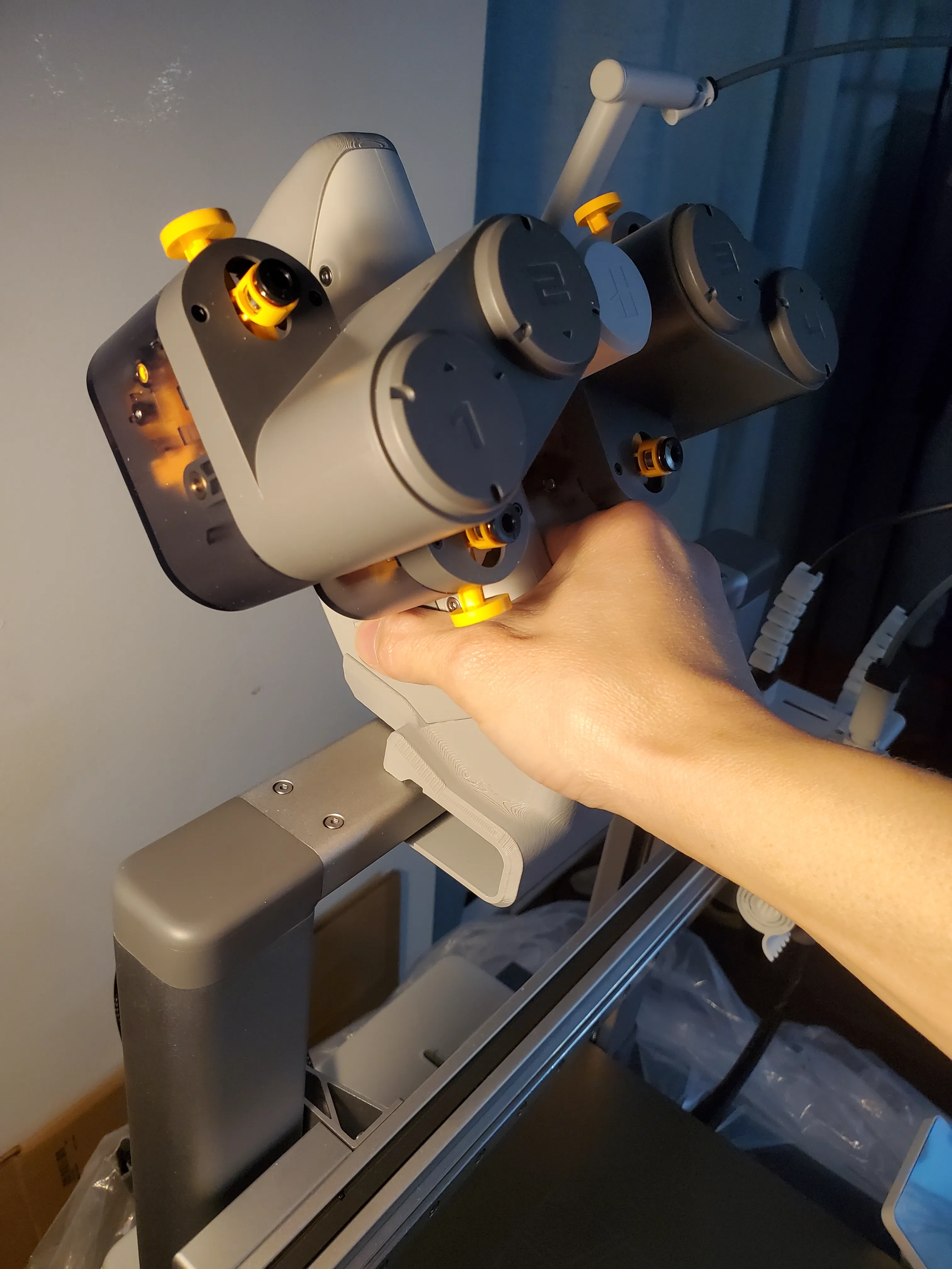
12. Insert the base locking block into the base from the side of the opening.
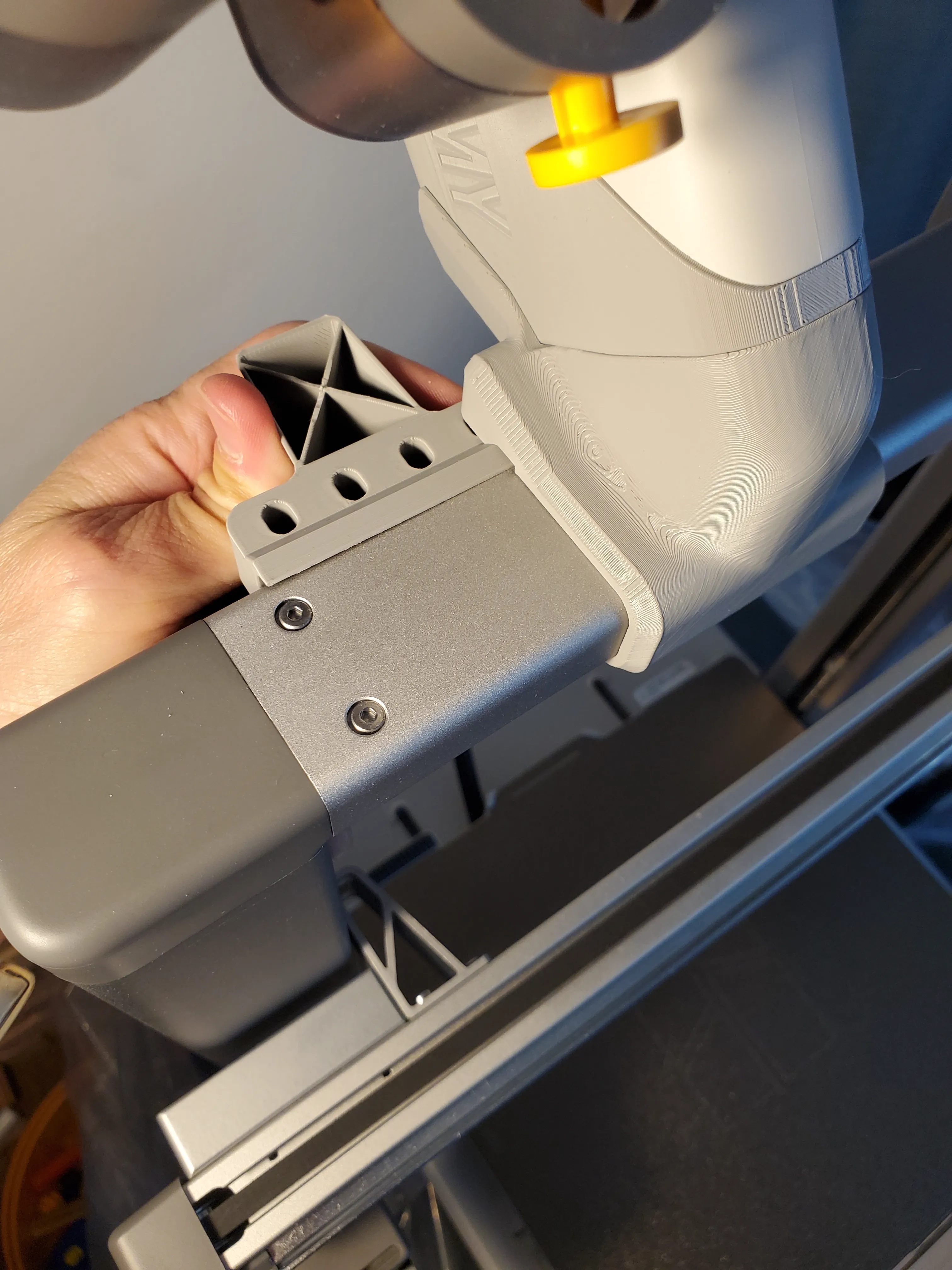
13. Secure the base using four 8 x 1-¼ inch pan head wood screws from below. The base locking block incorporates a gap-eliminating clamping mechanism; use appropriate screw tightening force to ensure proper clamping.
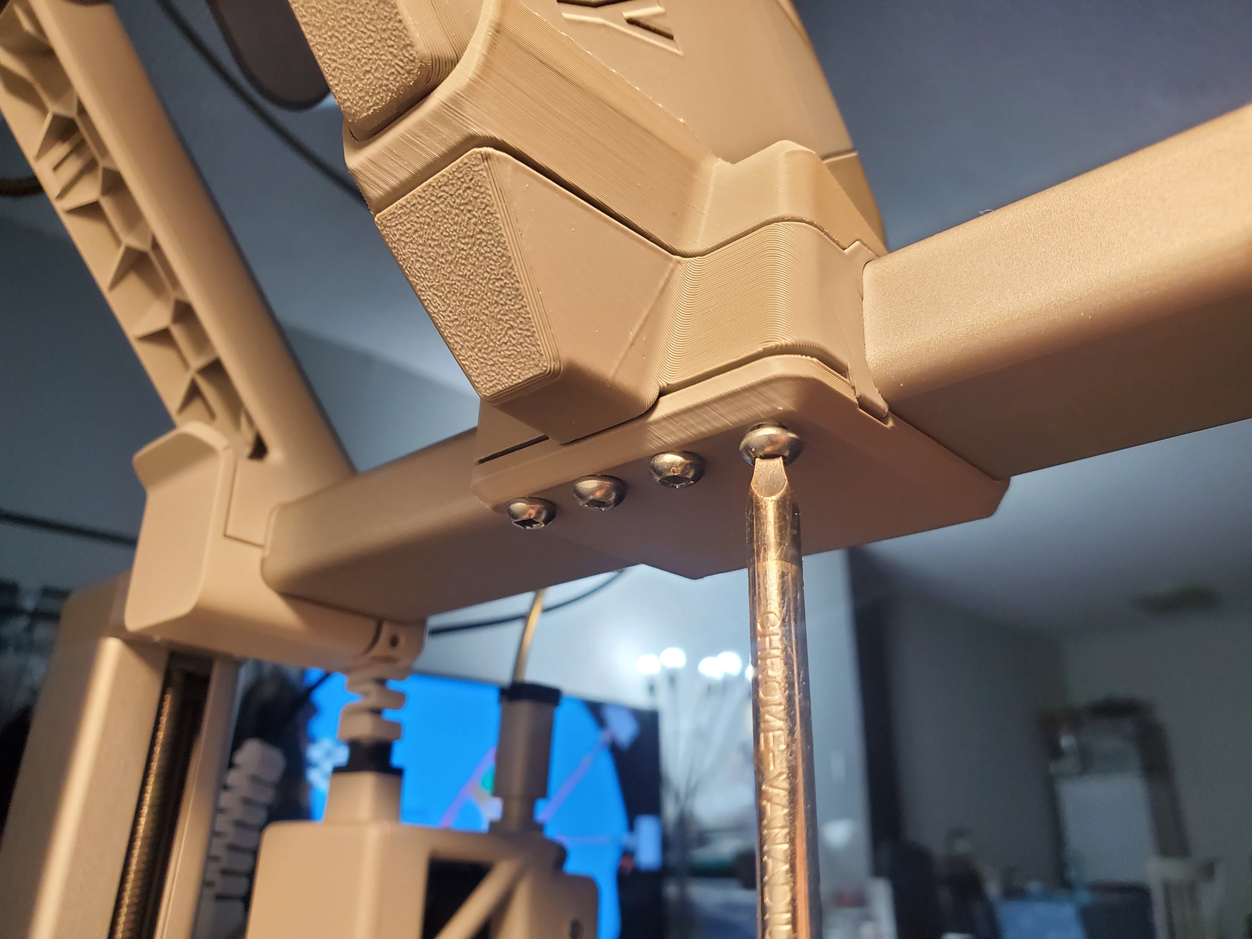
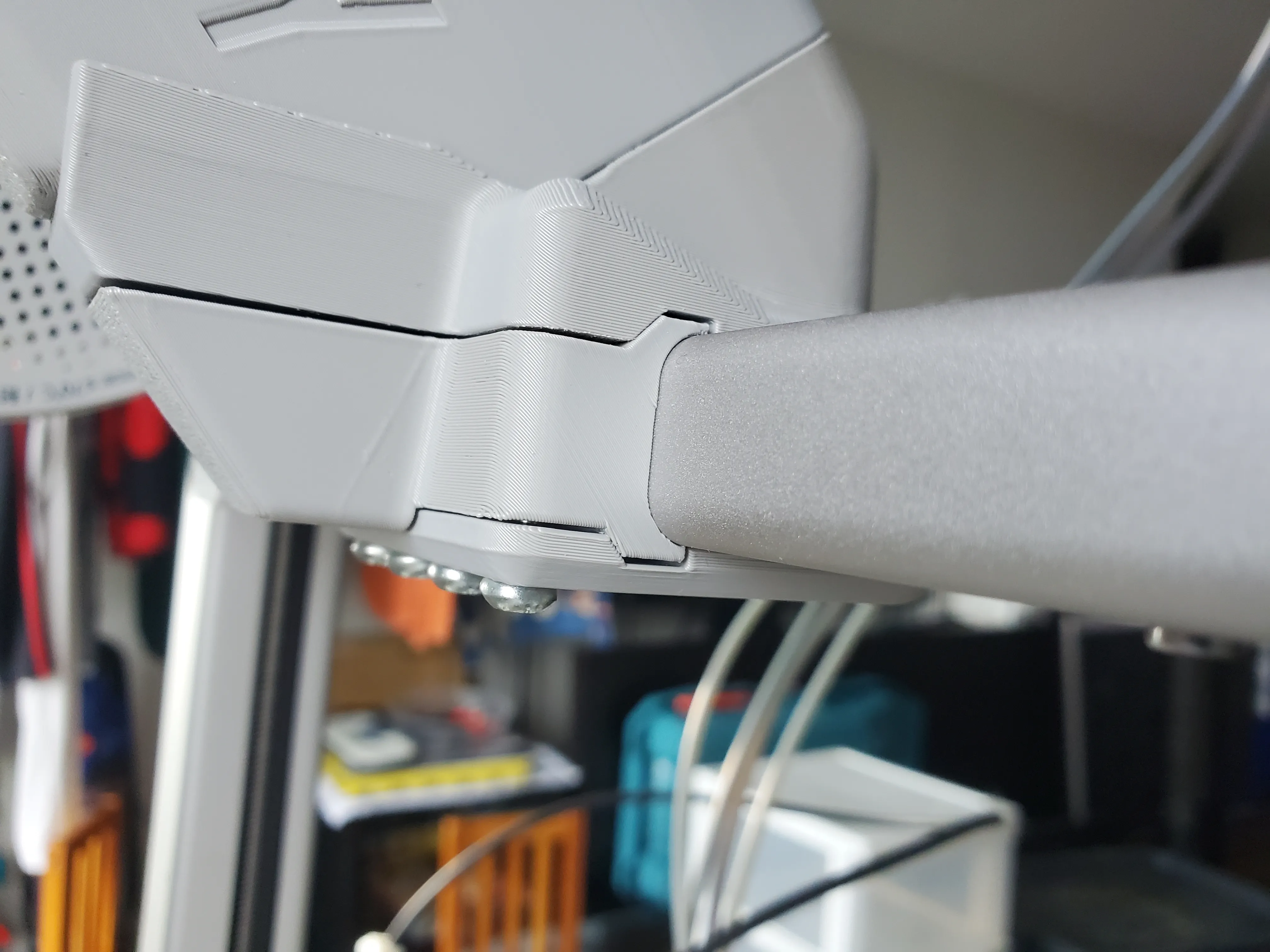
14. Insert the AMS cable through the cable entry point at the rear of the housing.
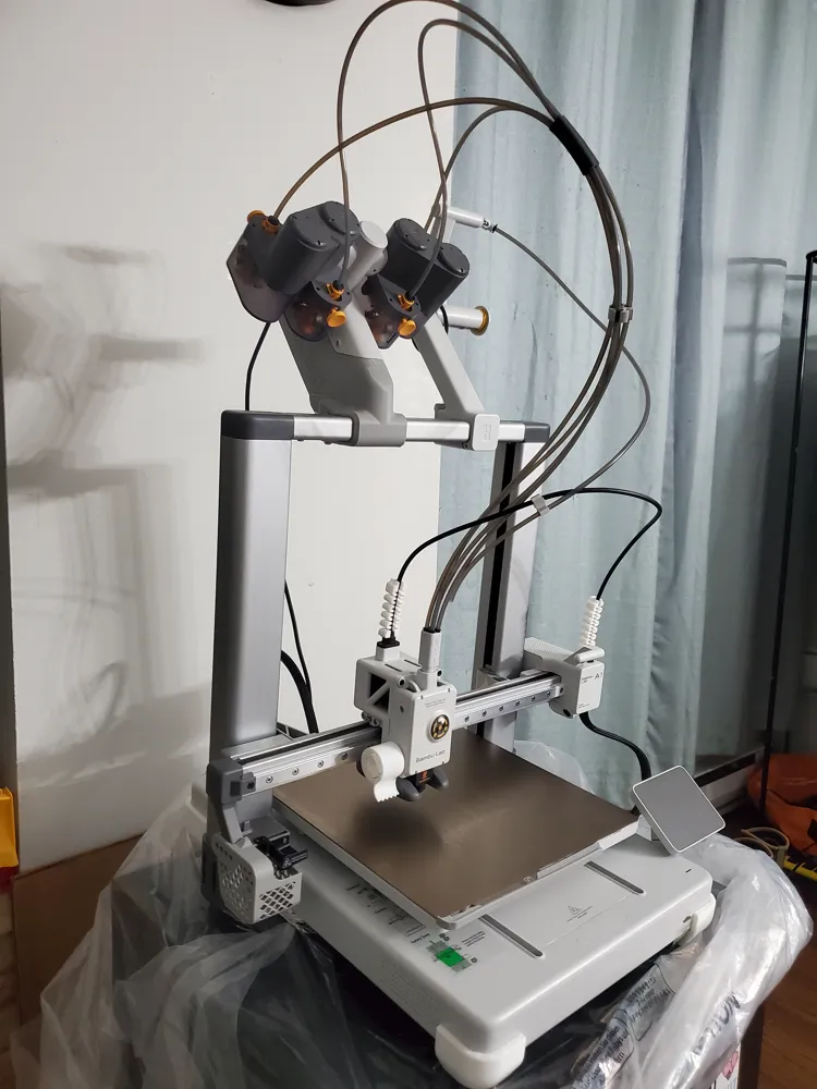
15. It is recommended to route the PTFE tubing as shown in the diagram.
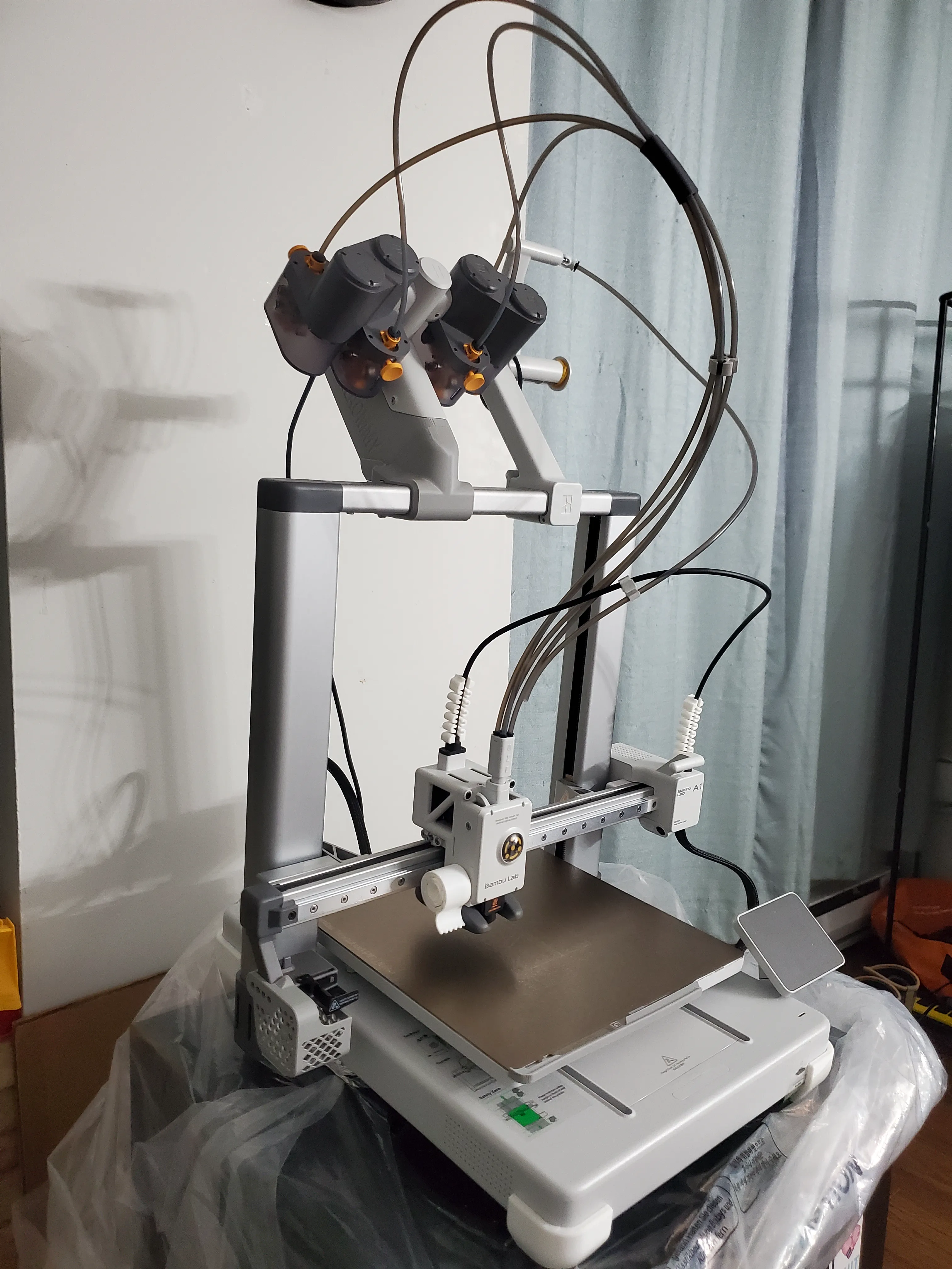
16. Manually move the print head through its full range of motion. Pay particular attention to the X-axis crossbeam at its highest position to ensure that all cables and PTFE tubing are clear of obstructions.
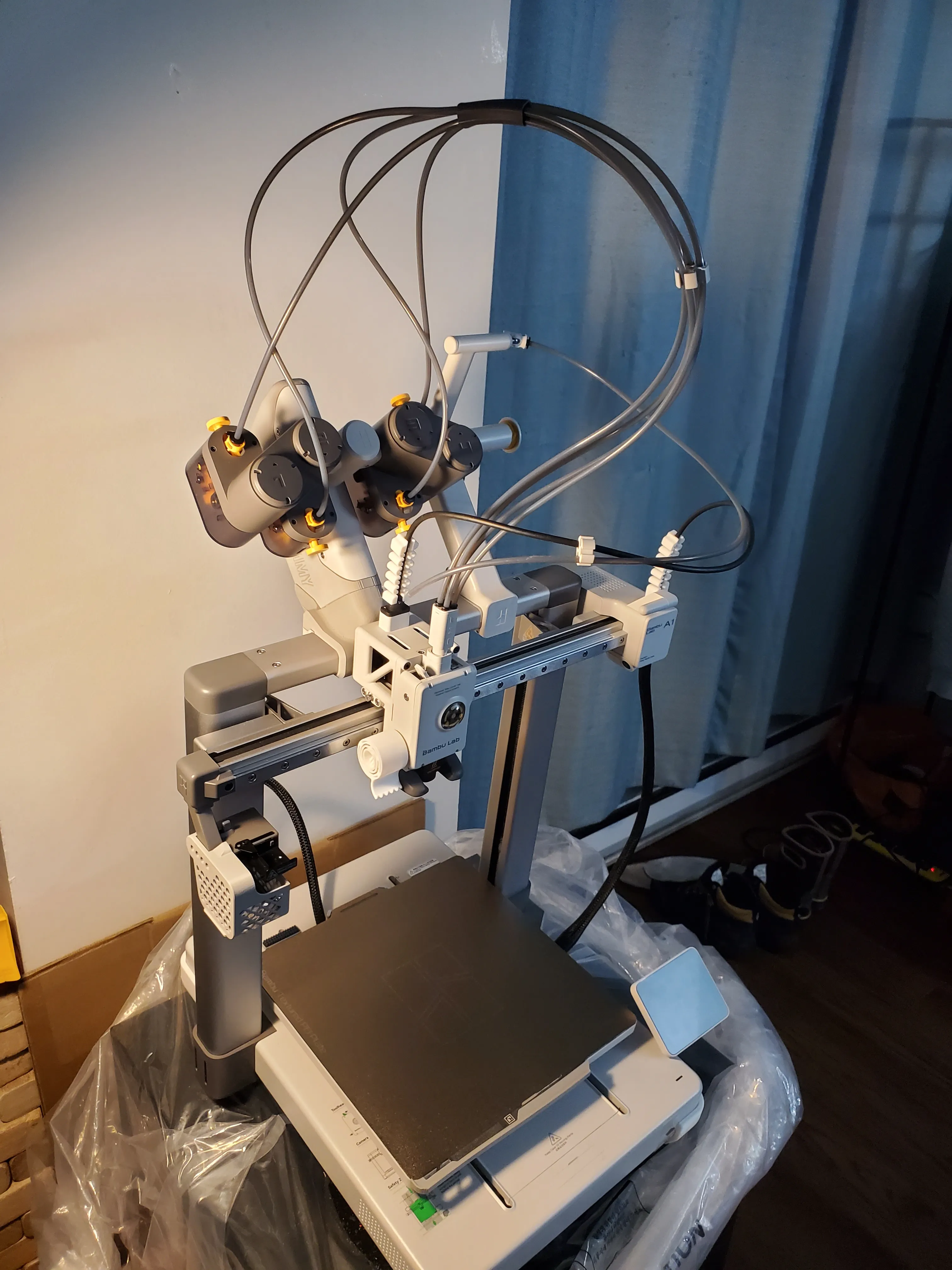
17. A final note: The released model's logo differs slightly from my personal printed version. My personal housing features a customized logo. This minor logo discrepancy should not affect printing or assembly. Please contact me if you encounter any issues. Continuous improvements will be made. Thank you!
License

You shall not share, sub-license, sell, rent, host, transfer, or distribute in any way the digital or 3D printed versions of this object, nor any other derivative work of this object in its digital or physical format (including - but not limited to - remixes of this object, and hosting on other digital platforms). The objects may not be used without permission in any way whatsoever in which you charge money, or collect fees.


Comment & Rating (6)