
Multimedia Key Deck
Print Profile(1)

Description
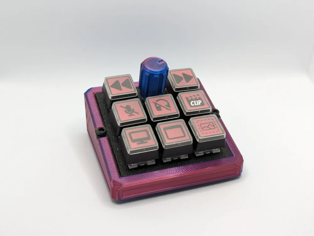
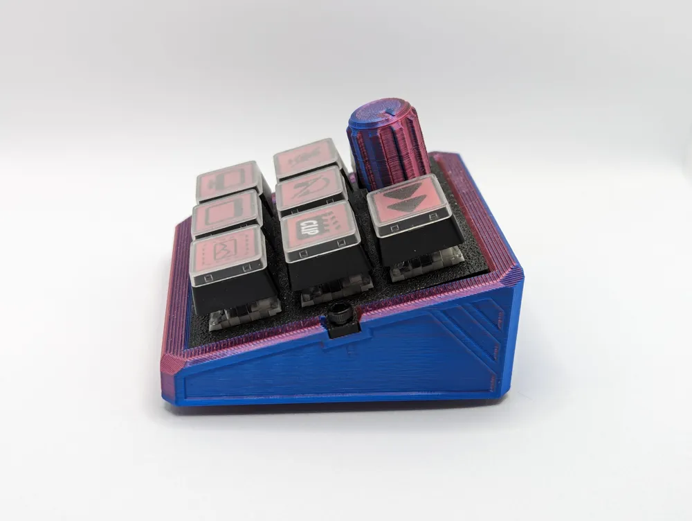
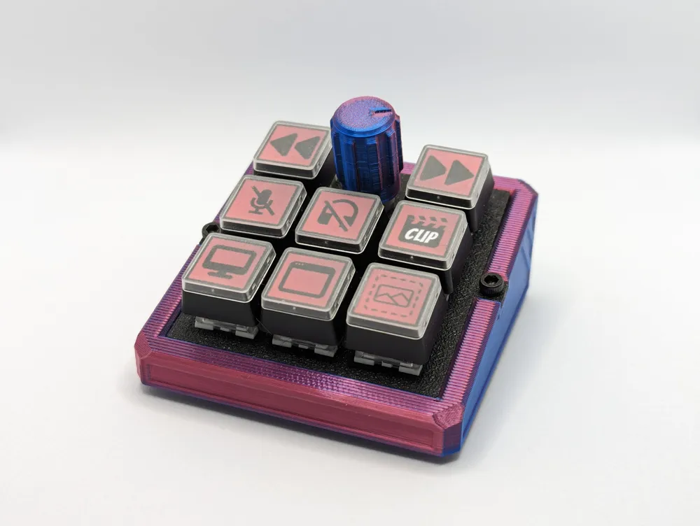
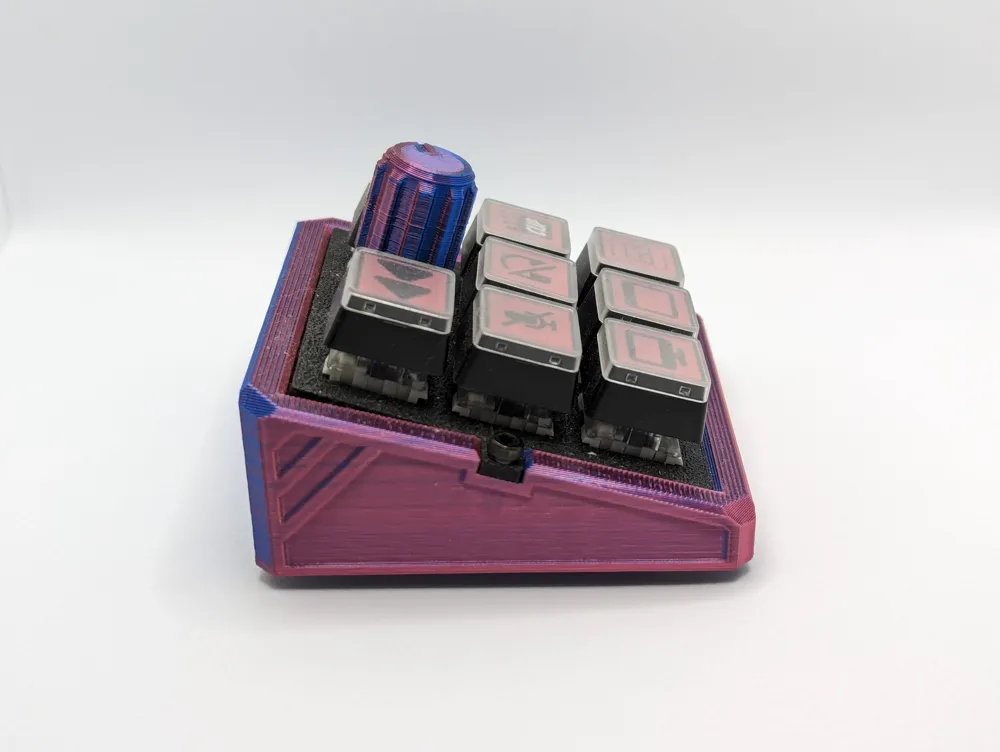
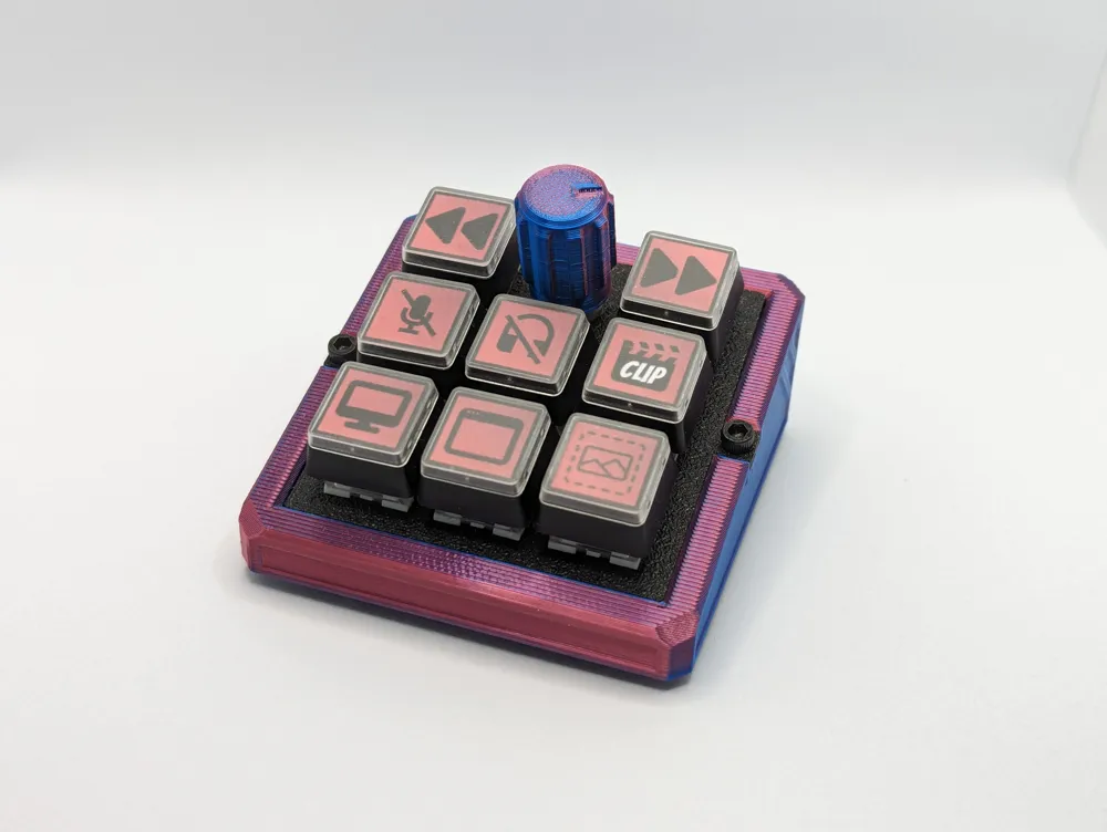
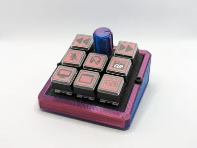
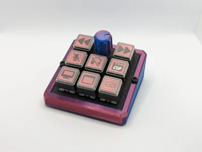
This is a simple and easy multimedia key deck which has 4 multimedia functions and six extra keys for binding.
This includes an encoder for volume control which also had a play/pause function. Then there is a forwards and backwards track buttons either side of the encoder. This is then followed by six extra function keys that you can bind to whatever you want!
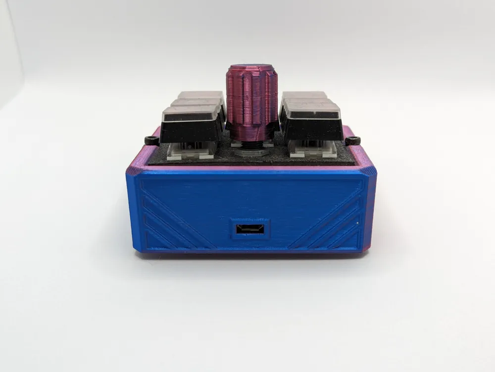
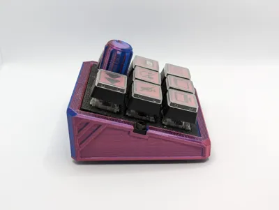
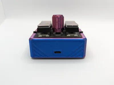
I suggest the use of supports on the base of the unit as there is a slight lip around the edge to help support the keypad base and the USB hole will need support.
There is now a V2 Base which includes a slot for a screwdriver to make removing the pro micro easier, moved the branding from the bottom of the pad to the inside so it makes it an easier print on the first layer too.
There will be a zip file included which contains the Arduino sketch and a wiring diagram for the encoder and the switch wiring guide.
Bill of Materials:
- 8x Kailh Box Switches (any colour you want)
- 8x Relegendable keycaps
- 1x Rotary encoder (I used these, they come with a threaded nut that you use to clamp the encoder to the key holder - https://amazon.co.uk/dp/B07D356LRH)
- 1x Arduino Pro Micro
- 1x Micro USB cable
- 3D Printed Pieces
- Stranded 28AWG wire
- 2x M3x6 Cap Head Bolts
The best way to put this together is to put all switches in to the holder, then you will want to solder all the ground pins of the switches together so that you can run one wire off the ground posts of the switches and on to one ground pad of the pro micro.
You will then need to have one wire for each post of the switch which is then wired to a numbered pad on the pro micro. The diagram included shows what each pad is programmed to function as. Its best to put the skip track buttons on either side of the encoder.
Once the switches have had wires added to them, its time to wire the encoder. You will need to remove the header from the encoder if yours came with one already soldered in, then solder in your own wires. Then you can follow the wiring diagram included.
Be careful with the length of your wires, the bottom row of switches can be pushed out of the holder if your wires aren't angled to the sides rather than straight up. Also make sure to use some double sided tape or some sort of adhesive to stick the pro micro down inside the case to ensure it doesnt move when you plug in your USB cable.
When programming the Arduino with the INO file you must make sure you download the two included libraries before you upload the sketch to the pro micro. The two libraries are HID-Project by NicoHood and Encoder by Paul Stoffregen.
License



Comment & Rating (3)