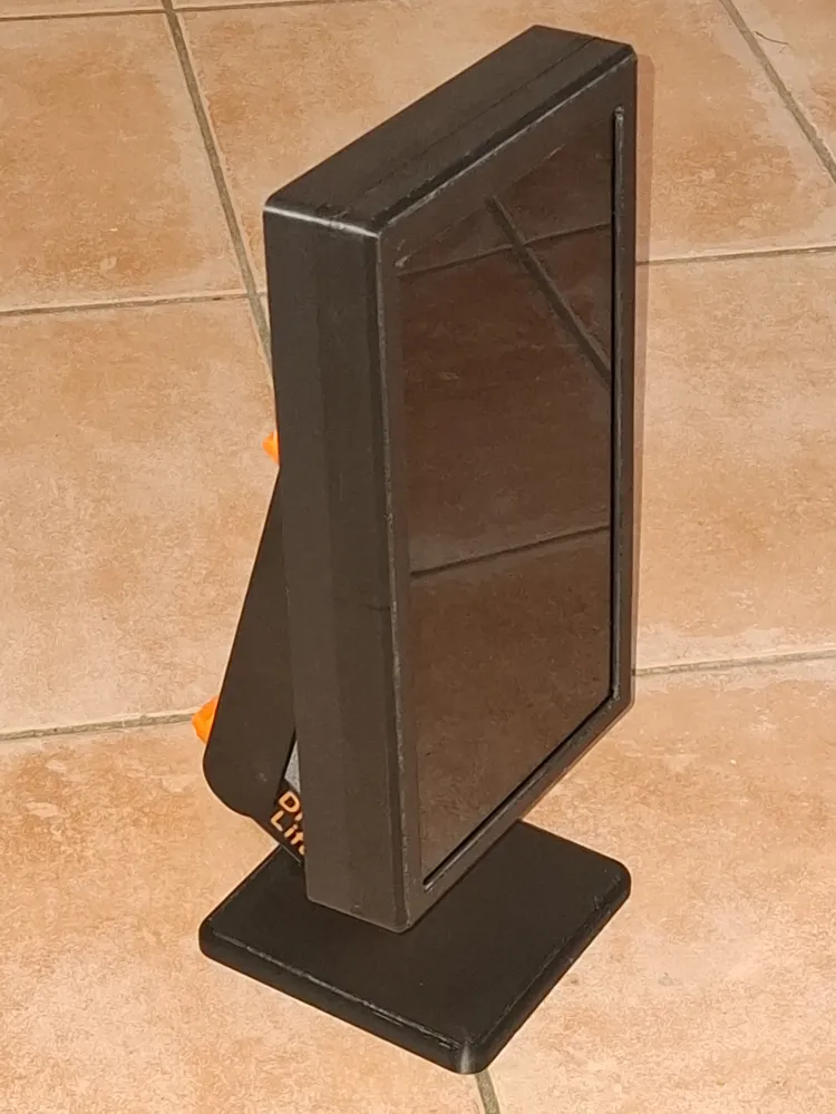
Case for RaspBerry Pi 3B + 10.1” Touch Display


Print Profile(2)

Description
German | English |
|
|
German
- After displaying our association's current schedule on a 24-inch outdoor display, we conceived a smaller, interior version showing the same information
- The technical solution remains essentially unchanged
- A Raspberry Pi 3B wirelessly loads the schedule page from our website and displays it on the monitor (portrait orientation)
- The schedule is updated regularly
- No user interaction is required
Unfortunately, we found no commercially available enclosure suitable for combining the small monitor and Raspberry Pi
- Enclosure requirements:
- A simple, robust design
- Power supply via USB power adapter
- Internal wiring between display and Raspberry Pi
- VESA 75 standard wall mount
The Raspberry Pi ports need not be accessible as control is entirely wireless
- Design challenges:
- Easy to print using a Bambu Lab X1C (or P1S/P or A1)
The display ports (HDMI + micro-USB) extend beyond the edge, necessitating angled connectors to minimize the print width
- Technical solution:
- Power supply:
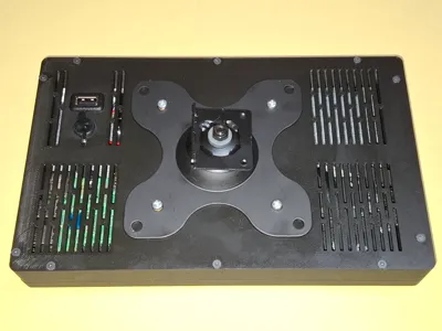
Two USB ports (Type A and Type C) were integrated in parallel on the rear panel. Both ports connect to the display's power supply and the Raspberry Pi's GPIO connector (+5V=Pin2+4, GND=Pin6) - Angled connectors were only available in a fixed 50cm length and could not be shortened (ribbon cable). Careful routing was essential to avoid kinks
- To prevent overheating of the Raspberry Pi:
- A passive heatsink was affixed
- Ventilation slots were incorporated into the rear panel
- The Raspberry Pi's waste heat rises, drawing cooler ambient air through the ventilation slots
- A readily accessible slider conceals the connection area for optional keyboard or LAN connection
To stay within a 255mm print width, the walls incorporating the threaded inserts had to be exceptionally narrow
- Power supply:
Assembly issues:
- Most issues were preemptively addressed using FreeCAD, with the Raspberry Pi and display modeled as simplified placeholder objects
- Unforeseen was the GPIO pins 2-6 placement beneath the rear panel reinforcement for the wall mount, requiring slight bending of the connector strip due to insufficient clearance above. This issue is rectified in this revised version, providing full height clearance
Assembly sequence:
- Weld in the threaded inserts into the front panel (10x M3)
- Attach the Raspberry Pi spacers to the Raspberry Pi using the screws
- Mount the Raspberry Pi onto the display and secure with screws
- Wiring:
- Install the two USB ports into the rear panel, loosely tightening the Type C nut
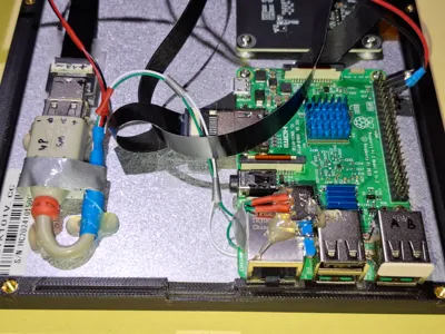
- Connect the HDMI cable to the display, carefully routing it around the circuit board to manage excess length, then connect it to the Raspberry Pi
- Connect the micro-USB connector to the display, and creatively shorten it
- Instead of soldering the power supply to the USB-C connector, I hot-glued another USB-C panel mount socket to the back of the display and plugged in the USB connector (Note the “Optional Touch Function”)
- Connect the cable from this USB port to the external USB ports via a short extension cable
- Finally, solder a small connector strip to the end of this power supply cable, and plug it into the Raspberry Pi's GPIO header (red/+5V=Pin 2+4, black/GND=Pin 6)
- Carefully attach the rear panel to the front panel.
- Ensure no cables are pinched
- Insert the slider with the small operating handle facing outwards
- Proceed with extreme caution as the 8 pressure springs holding the display against the front panel are delicate
- Insert the 10 screws (M3x30) and avoid overtightening
- Now weld in the threaded inserts for the wall mount (4x M4)
(Premature installation might overstress the pressure springs and cause breakage) - Attach the wall mount headpiece using 4 screws
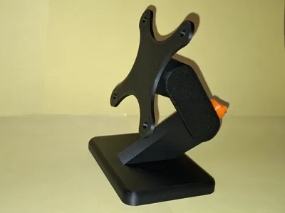
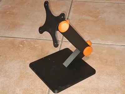
Alternatively, attach the VESA mount from the optional table stand
- 3D Printing
- Larger parts print best positioned at the right edge of the print bed. Leftward placement risks the print head repeatedly contacting the small lever, resulting in noise and potential long-term damage
CAUTION: Remove the calibration strips from the front edge immediately after printing. Later removal is laborious and leaves unsightly marks.
- Materials
- Threaded inserts 10x M3 and 4x M4 (standard parts)
- Screws 10x M3x30, countersunk head
- 1x USB Type-C panel mount socket
- 2x USB Type-A panel mount socket (USB extension cable for touch option)
- Angled HDMI connector, ribbon cable
- Angled micro-USB connector, ribbon cable
- 3-pin header for GPIO connection (scrap parts)
- Wiring (red and black, scrap parts)
- Raspberry Pi Model 3B
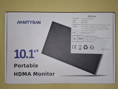
- 10.1” Monitor/Display
Used here: HAMTYSAN 10.1” Portable HDMA Monitor (234x143x7.3mm³) Wall mount
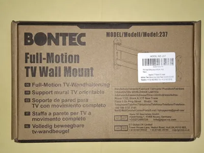
Used here: BONTEC Full-Motion TV Wall Mount, Model:237
- Optional Touch Function
- Our project does not require touch functionality; indeed it would be detrimental as visitors could alter settings. The initial design included only the USB power supply for the display, omitting data connectivity
- However, I recognize that this feature holds considerable appeal for general use
- Therefore I expanded the project to include data connectivity.
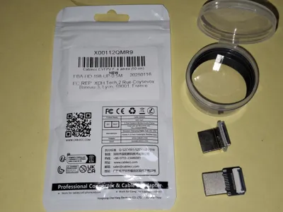
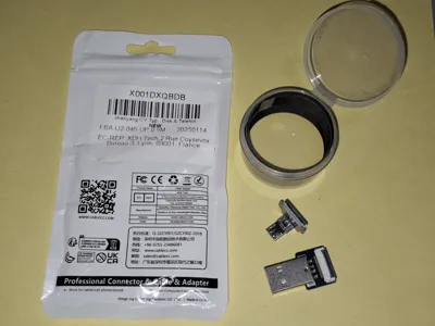
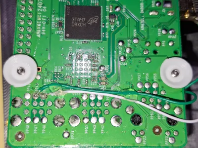
- Instead of a power-only USB panel mount, I repurposed a USB extension cable, providing data lines soldered directly to the Raspberry Pi (see photos)
- Consequently, the associated USB port must remain unused and is capped with a blank plug
- To prevent unwanted touch input, a data line is controlled via a switch affixed to the LAN port. A fine-tipped instrument can activate the hidden switch to enable touch when necessary
English
- After displaying our association's current schedule on a 24-inch outdoor display, we conceived a smaller, interior version showing the same information
- The technical solution remains essentially unchanged
- A Raspberry Pi 3B wirelessly loads the schedule page from our website and displays it on the monitor (portrait orientation)
- The schedule is updated regularly
- No user interaction is required
Unfortunately, we found no commercially available enclosure suitable for combining the small monitor and Raspberry Pi
- Enclosure requirements:
- A simple, robust design
- Power supply via USB power adapter
- Internal wiring between display and Raspberry Pi
- VESA 75 standard wall mount
The Raspberry Pi ports need not be accessible as control is entirely wireless
- Design challenges:
- Easy to print using a Bambu Lab X1C (or P1S/P or A1)
The display ports (HDMI + micro-USB) extend beyond the edge, necessitating angled connectors to minimize the print width
- Technical solution:
- Power supply:
- Two USB ports (Type A and Type C) were integrated in parallel on the rear panel. Both ports connect to the display's power supply and the Raspberry Pi's GPIO connector (+5V=Pin2+4, GND=Pin6)
- Angled connectors were only available in a fixed 50cm length and could not be shortened (ribbon cable). Careful routing was essential to avoid kinks
- To prevent overheating of the Raspberry Pi:
- A passive heatsink was affixed
- Ventilation slots were incorporated into the rear panel
- The Raspberry Pi's waste heat rises, drawing cooler ambient air through the ventilation slots
- A readily accessible slider conceals the connection area for optional keyboard or LAN connection
To stay within a 255mm print width, the walls incorporating the threaded inserts had to be exceptionally narrow
- Power supply:
- Assembly issues:
- Most issues were preemptively addressed using FreeCAD, with the Raspberry Pi and display modeled as simplified placeholder objects
- Unforeseen was the GPIO pins 2-6 placement beneath the rear panel reinforcement for the wall mount, requiring slight bending of the connector strip due to insufficient clearance above. This issue is rectified in this revised version, providing full height clearance
- Assembly sequence:
- Weld in the threaded inserts into the front panel (10x M3)
- Attach the Raspberry Pi spacers to the Raspberry Pi using the screws
- Mount the Raspberry Pi onto the display and secure with screws
- Wiring:
- Install the two USB ports into the rear panel, loosely tightening the Type C nut
- Connect the HDMI cable to the display, carefully routing it around the circuit board to manage excess length, then connect it to the Raspberry Pi
- Connect the micro-USB connector to the display, and creatively shorten it
- Instead of soldering the power supply to the USB-C connector, I hot-glued another USB-C panel mount socket to the back of the display and plugged in the USB connector (Note the “Optional Touch Function”)
- Connect the cable from this USB port to the external USB ports via a short extension cable
- Finally, solder a small connector strip to the end of this power supply cable, and plug it into the Raspberry Pi's GPIO header (red/+5V=Pin 2+4, black/GND=Pin 6)
- Carefully attach the rear panel to the front panel.
- Ensure no cables are pinched
- Insert the slider with the small operating handle facing outwards
- Proceed with extreme caution as the 8 pressure springs holding the display against the front panel are delicate
- Insert the 10 screws (M3x30) and avoid overtightening
- Now weld in the threaded inserts for the wall mount (4x M4)
(Premature installation might overstress the pressure springs and cause breakage) Attach the wall mount headpiece using 4 screws
Alternatively, attach the VESA mount from the optional table stand
- 3D Printing
- Larger parts print best positioned at the right edge of the print bed. Leftward placement risks the print head repeatedly contacting the small lever, resulting in noise and potential long-term damage
CAUTION: Remove the calibration strips from the front edge immediately after printing. Later removal is laborious and leaves unsightly marks.
- Materials
- Threaded inserts 10x M3 and 4x M4 (standard parts)
- Screws 10x M3x30, countersunk head
- 1x USB Type-C panel mount socket
- 2x USB Type-A panel mount socket (USB extension cable for touch option)
- Angled HDMI connector, ribbon cable
- Angled micro-USB connector, ribbon cable
- 3-pin header for GPIO connection (scrap parts)
- Wiring (red and black, scrap parts)
- Raspberry Pi Model 3B
- 10.1” Monitor/Display
Used here: HAMTYSAN 10.1” Portable HDMA Monitor (234x143x7.3mm³) Wall mount
Used here: BONTEC Full-Motion TV Wall Mount, Model:237
- Optional Touch Function
- Our project does not require touch functionality; indeed it would be detrimental as visitors could alter settings. The initial design included only the USB power supply for the display, omitting data connectivity
- However, I recognize that this feature holds considerable appeal for general use
- Therefore I expanded the project to include data connectivity.
- Instead of a power-only USB panel mount, I repurposed a USB extension cable, providing data lines soldered directly to the Raspberry Pi (see photos)
- Consequently, the associated USB port must remain unused and is capped with a blank plug
- To prevent unwanted touch input, a data line is controlled via a switch affixed to the LAN port. A fine-tipped instrument can activate the hidden switch to enable touch when necessary
License
You shall not share, sub-license, sell, rent, host, transfer, or distribute in any way the digital or 3D printed versions of this object, nor any other derivative work of this object in its digital or physical format (including - but not limited to - remixes of this object, and hosting on other digital platforms). The objects may not be used without permission in any way whatsoever in which you charge money, or collect fees.
Comment & Rating (2)