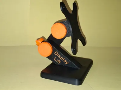
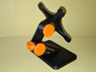
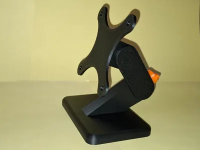
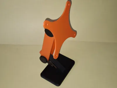
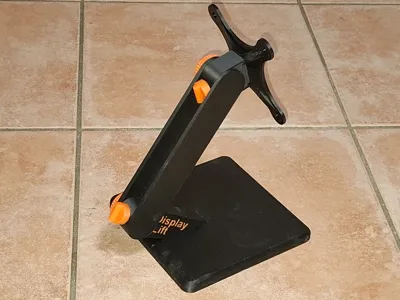
Display-Lift VESA desktop stand


Print Profile(6)


Description
German | English |
|
|
German
- I created a compact housing for the Raspberry Pi and a 10.1” touch display. For my application, I needed a wall mount according to the VESA standard.
- So far, so good, everything worked.
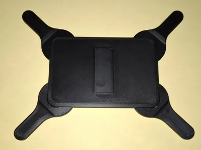
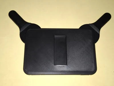
- But not everyone wants a wall mount for their Raspi. The desire arose to retrofit the case with a “normal” table stand so that everyone could use the case. And this is what came out...
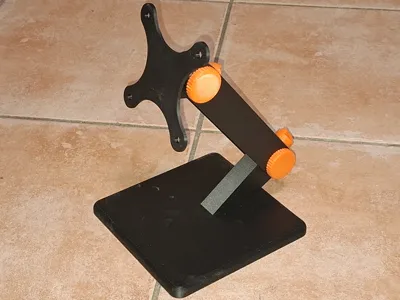
- The height and tilt of the stand are adjustable. The height adjustment can be locked to prevent heavier devices from sagging.
If the stand is to be used for devices of a different size, only the 50mm arm needs to be replaced with a different length. Lengths included in the list of stl files: 40, 50, 60, 70, 80, 90, 100, 120, and 150mm (distance between the rotation axes).
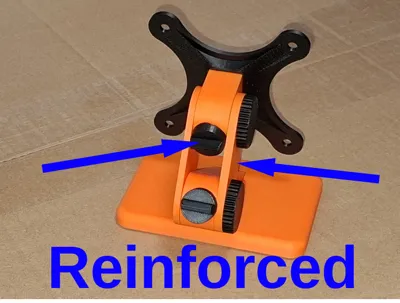
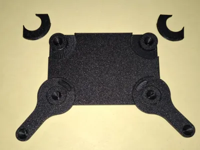
- Optional reinforcement
- If the panel to be mounted is heavy, the fixable “Tilt-Joint_(fixable).stl” should be used instead of the upper tilt joint “Tilt-Joint.stl” to prevent unintentional tilting. This requires an additional fixing button “Fixing-Button.stl”.
And if you want a little more lateral stability, you can attach an additional reinforcement arm “Joint-Arm_(XXmm)_reinforce” with the fixing screw.
Optional stabilization
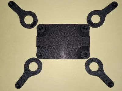
- For larger and/or heavier devices, the base plate may be too small.
- For this purpose, a variant of the base plate has been developed that can be fitted with supports that allow the center of gravity of the mounted device to be outside the plate.
- Up to 4 stabilizers can be used if necessary.
- The stabilizers are widely adjustable and can therefore be adapted to any requirement.
- The stabilizers are included in sizes 30, 40, 50, 70, 100, and 150mm (distance between the two hole centers).
- A blanking plate can be used in corners that do not require a stabilizer (for visual appearance).
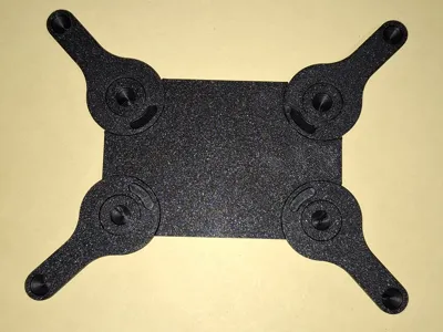
- If rubber feet are to be used, they must also be mounted in ALL possible positions (the round feet in the base plate, as well as the round and the small elongated feet in the stabilizers).
- Of course, the rubber feet can also be omitted completely.
- Important: If you are already using the previous base plate, you can simply replace it with the new version. The joint holder can be removed from the old plate with a little force and inserted into the new one.
- Assembly
- Insert the rubber feet into the bottom plate. A firm push should suffice.
- Insert the joint holder into the bottom plate:
- First, insert the rounded tip into the recess provided, then give the other end a firm, short tap.
- Dismantling is just as easy; all it takes is a firm tug on the joint holder.
- Attach the fixing button to the joint holder:
- Press the joint holder gap together slightly.
- Place the fixing button over the mounting cylinder, making sure that the small operating knob is horizontal.
- Release the joint holder; the fixing button now holds on its own.
- Press one of the joint arm rollers into the joint holder. It is slightly easier if the fixing button is vertical.
- Turn a fixing screw into the roller. This screw only prevents the construction from falling apart and has no influence on the firmness of the adjustment function.
- Click the VESA holder into the tilt joint:
The tilt joint is pressed into the corresponding recess with the small bead located at the very edge. The hinge part now rests on the edge on the other side. A suitable object (in my case, a screwdriver with a wide blade) is placed on the overlying bead. 

- With another firm blow on the screwdriver, this bead is brought into the recess provided for it.
- This is a little more difficult than with the base plate.
- And unlike the base plate, this “marriage” of the parts cannot be reversed without damaging them.
- Press the tilt joint onto the other roller of the joint arm. Please note that the part of the VESA holder where the bead was “hammered in” with the tool is facing downwards. This can be recognized by the visible chamfer. This alignment is not really important; it only optimizes the force vectors of the mount.
- Screw in the other fixing screw.
DONE!
- Instructions for installing the version with stabilizers
- The stabilizers are pressed in with a little force. It is slightly easier if the stabilizer is twisted so that the bead that has to be pressed into the groove is partially outside the base plate.
- Removal is just as easy: press your thumb on the pivot point and pull on the long arm.
- The stabilizers can be easily rotated in the desired direction.
If the blanking plate is to be used instead of a stabilizer, it is rotated 180 degrees without force and then screwed into the groove.
- Operation/function
- Height adjustment by turning the joint arm:
- Set the fixing button vertically.
- Move the joint arm with a little force.
- Set the locking button to horizontal again so that even a heavy weight cannot pull the joint arm down.
- Adjust the inclination
- Adjust the desired inclination by pushing/pulling on the device mounted on the VESA mount.
As the force vectors are smaller here, there is no need for a fixation.
- Height adjustment by turning the joint arm:
3D printing
- I used the new Bambu Lab TPU90A for the rubber feet. With TPU95A, the feet could possibly be a little harder. If they cannot be inserted, then print the feet a little smaller.
- If a reinforced arm “Joint-Arm_(XXmm)_reinforce.stl” is to be printed, this requires support. To do this, draw a circle around the two holes from below in the slicer in manual mode.
- Material
- I tested the table stand with Bambu’s PLA Basic - PETG should also be possible without modification.

English
- I created a compact housing for the Raspberry Pi and a 10.1” touch display. For my application, I needed a wall mount according to the VESA standard.
- So far, so good, everything worked.
- But not everyone wants a wall mount for their Raspi. I wanted to retrofit the case with a “normal” table stand so that everyone could use the case. And this is the result …
- The height and angle of the stand can be adjusted. The height adjustment can be locked to prevent heavier devices from sinking.
If the stand is to be used for devices of a different size, only the 50mm-arm needs to be exchanged for a different length. Lengths included in the list of stl files: 40, 50, 60, 70, 80, 90, 100, 120 and 150mm (distance between the rotation axes).
Optional reinforcement
- If the panel to be mounted is heavy, the fixable “Tilt-Joint_(fixable).stl” should be used instead of the upper tilt joint “Tilt-Joint.stl” to prevent unintentional tilting. This requires an additional fixing button “Fixing-Button.stl”.
- And if you want a little more lateral stability, you can use the fixing screw to attach an additional reinforcement arm “Joint-Arm_(XXmm)_reinforce”.
- Optional stabilization
- The base plate may be too small for larger and/or heavier devices.
- For this purpose, a variant of the base plate has been developed that can be fitted with supports that allow the center of gravity of the mounted device to be outside the plate.
- Up to 4 stabilizers can be used if necessary.
- The stabilizers are widely adjustable and can therefore be adapted to any requirement.
- The stabilizers are included in sizes 30, 40, 50, 70, 100, and 150 mm (distance between the two hole centers).
- A blanking plate can be used in corners that do not require a stabilizer (for visual appearance).
- If rubber feet are to be used, they must be mounted in ALL possible positions (the round feet in the base plate and the round and small elongated feet in the stabilizers).
- Of course, the rubber feet can also be omitted completely.
Important: If you are already using the previous base plate, you can simply replace it with the new version. The joint holder can be removed from the old plate with a little force and inserted into the new one.
Assembly
- Insert the rubber feet into the bottom plate. A firm push should suffice.
- Insert the joint holder into the bottom plate:
- First insert the rounded tip into the recess provided, then give the other end a firm, short tap.
- Dismantling is just as easy, all it takes is a firm tug on the joint holder.
- Attach the fixing button to the joint holder:
- Press the joint holder gap together slightly.
- Place the fixing button over the mounting cylinder, making sure that the small operating knob is horizontal.
- Release the joint holder, the fixing button now holds on its own.
- Press one of the joint arm rollers into the joint holder. It is slightly easier if the fixing button is vertical.
- Turn a fixing screw into the roller. This screw only prevents the construction from falling apart and has no influence on the firmness of the adjustment function.
- Click the VESA holder into the tilt joint:
The tilt joint is pressed into the corresponding recess with the small bead on the very edge. The hinge part now rests on the edge on the other side. Place a suitable object (in my case a screwdriver with a wide blade) on the overlying bead. 

- This bead is placed in the recess provided for it with another firm blow on the screwdriver.
- This is a little more difficult than with the bottom plate.
- And unlike the bottom plate, this “marriage” of the parts cannot be reversed without damaging the parts.
- Press the tilt joint onto the other roller of the joint arm. Please ensure that the part of the VESA holder where the bead was “hammered in” with a tool is facing downwards. This can be recognized by the visible chamfer. This alignment is not really important, it only optimizes the force vectors of the mount.
- Screw in the other fixing screw.
- DONE!
Instructions for installing the version with stabilizers
- The stabilizers are pressed in with a little force. It is slightly easier if the stabilizer is twisted so that the bead that has to be pressed into the groove is partially outside the base plate.
- Removal is just as easy: press your thumb on the pivot point and pull on the long arm.
- The stabilizers can be easily rotated in the desired direction.
- If the blanking plate is to be used instead of a stabilizer, it is rotated 180 degrees without force and then screwed into the groove.
- Operation/function
- Adjust the height by turning the joint arm:
- Set the fixing button vertically.
- Move the joint arm with a little force.
- Set the locking button to horizontal again so that even a heavy weight cannot pull the joint arm down.
- Adjust the inclination
- Set the desired inclination by pushing/pulling on the device mounted on the VESA mount.
As the force vectors are smaller here, there is no need for a fixation.
- Adjust the height by turning the joint arm:
3D printing
- I used the new BambuLab TPU90A for the rubber feet. With TPU95A, the feet could possibly be a little harder. If they cannot be inserted, then print the feet a little smaller.
- If a reinforced arm “Joint-Arm_(XXmm)_reinforce.stl” is to be printed, this requires support. To do this, draw a circle around the two holes from below in the slicer in manual mode.
- Material
- I tested the table stand with Bambu's PLA Basic - PETG should also be possible without modification.
License
You shall not share, sub-license, sell, rent, host, transfer, or distribute in any way the digital or 3D printed versions of this object, nor any other derivative work of this object in its digital or physical format (including - but not limited to - remixes of this object, and hosting on other digital platforms). The objects may not be used without permission in any way whatsoever in which you charge money, or collect fees.
Comment & Rating (58)