
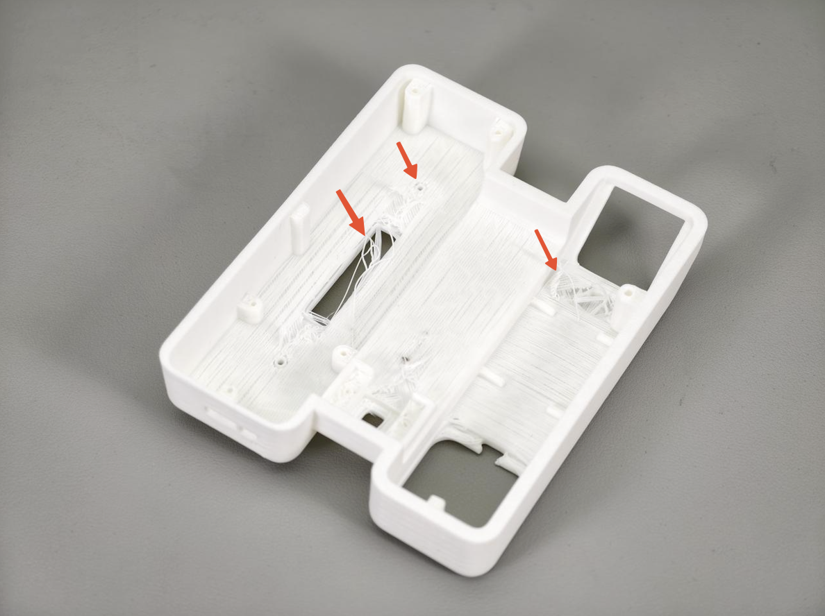
In the design of 3D printed parts, screw holes or through-holes are common features. These holes are key to putting parts together. They help with passing through a part or attaching a screw. However, in 3D printing, if there isn’t enough support material around the hole, it can create unsupported island toolpaths at the bottom. This results in a supportless hole. The print nozzle will struggle to cross the unsupported area and bridge because the bottom of the hole lacks solid support. Thus, bridging tends to fail, leading to the material around the supportless holes detaching. In the image below, you can see these bridging failures in detail. This image shows how such printing issues affect print quality.
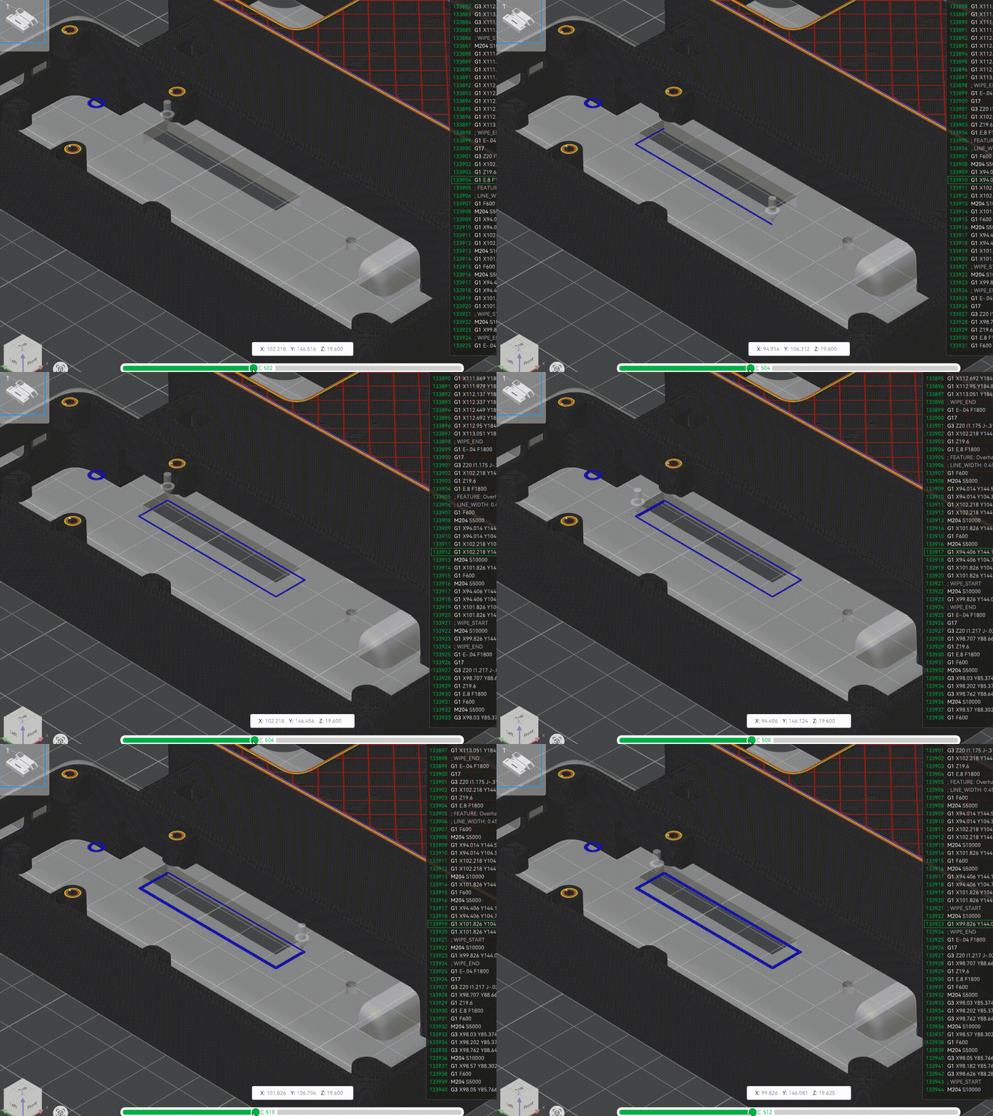
The dark blue lines represent the perimeter walls around the supportless hole. The toolpath sequence shows that this perimeter wall doesn't connect to the outer wall. This means it will be completely unsupported. This will cause the perimeter walls to detach during printing and result in filament sagging.
To solve the issue of filament sagging, we recommend using the following techniques. The techniques are sorted based on how the supportless hole relates in distance and shape to the outer wall.
- Draw bridging layers
- Adding supports around the supportless holes
- Design a chamfer
Small-diameter supportless holes with a short distance to the outer wall
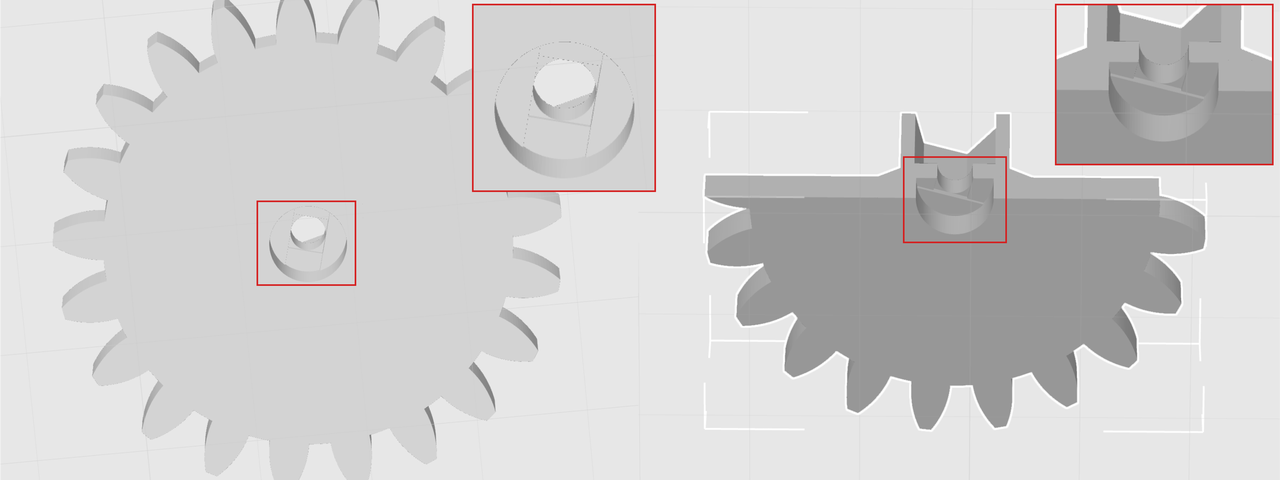
If the supportless hole is small and close to the outer wall, like with M3 screws, support structures might block it. It is hard to remove the support from the supportless hole. We recommend designing bridging layers to address this issue. You can find more on bridging layer design in different guides. Check out Vector 3D's video, "Avoid Supports, Sacrificial Layers and Bridging with this clever design technique'' on YouTube. Taking the Bambu Lab's Engine Model 005 as an example, the screw hole of the gear features a bridging layer design.
The bridging layer design carves multiple layers at the hole's base into a groove. This changes the toolpath from fully unsupported to supported by the outer wall. This creates many support points beneath the supportless wall, preventing filament sagging.
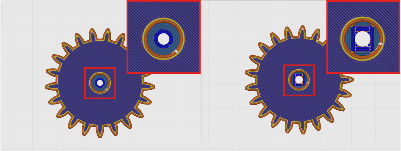
The completely unsupported island toolpaths are removed after applying the bridging layer design.
Draw the bridging layers by following these steps.
Step 1: Draw the first bridging layer. Sketch a racetrack shape on the surface of the supportless hole. Keep the two straight sides tangent to the edge of the supportless hole. Keep the other two sides coinciding with the outer wall contour. Extrude the racetrack shape inwards by 0.2 mm to form a racetrack groove.
Step 2: Draw the second bridging layer. Sketch a rectangle on the surface of the racetrack groove. Keep the rectangle's two sides at right angles to the racetrack groove's straight edges. They should be tangent to the edge of the supportless hole.
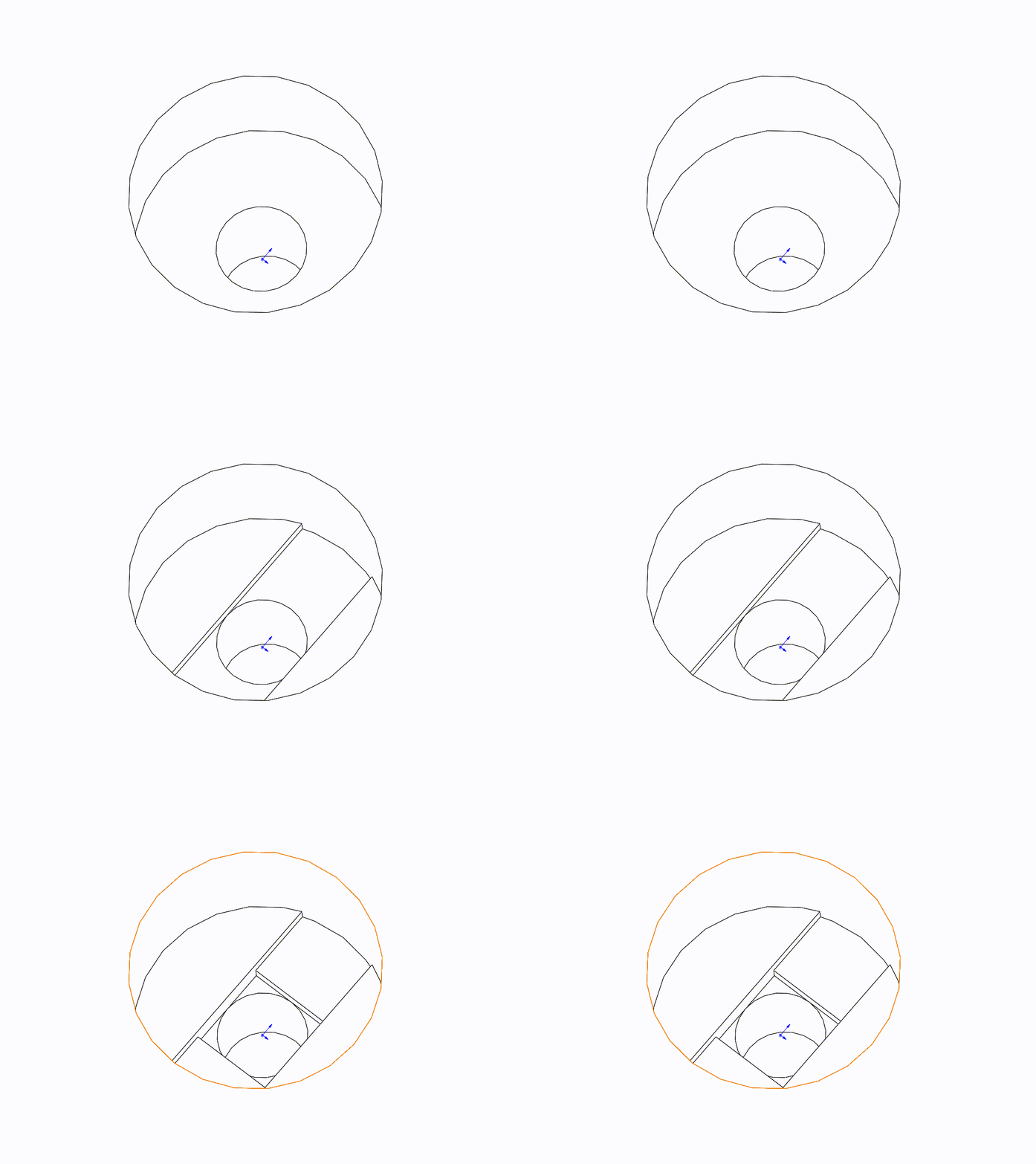
Big-diameter supportless holes with a long distance to the outer wall
If the supportless hole is large and far from the outer wall, we suggest adding support to the hole's wall and using bridging for better optimisation. Taking Bambu Lab's A1 Mini Wireless Charger as an example, it has various supportless holes and long bridges on its base. You need these features to install several components. These include induction coils, lamp panels, mainboards, and buttons. By adding supports around the supportless holes, this technique provides adequate support to the toolpaths at the edges of supportless holes and long bridges. In the example below, the selected areas are face-splitted first. For unprocessed models, you may need to draw with the circle pen tool manually.
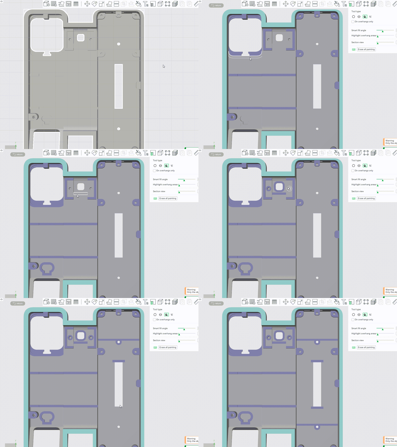
Compared to automatic support, this method significantly saves materials and print time while ensuring print quality. The image below shows that, compared to automatic support, adding support and using bridging saves 19.96 grams of filament and reduces printing time by 28 minutes.
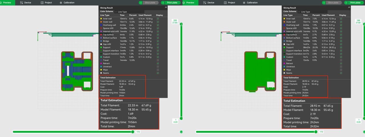
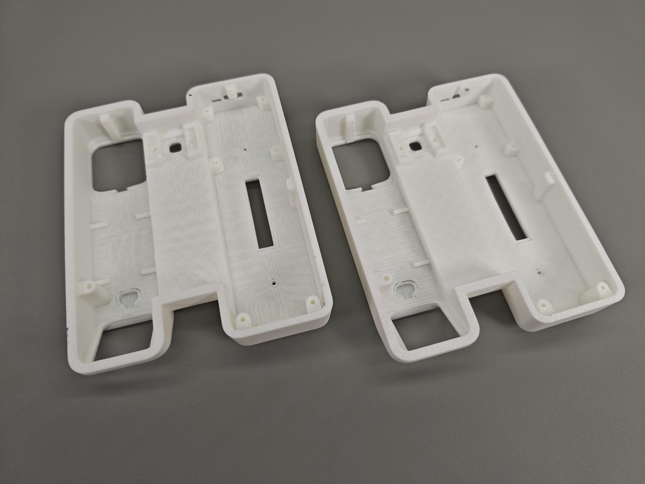
The left image shows the result of adding supports and using bridging. The right image displays the effect of using automatic support. As shown in the image below, there is no noticeable difference in quality.
When the shape of the supportless hole matches the outer wall, and there is enough space above it
If the shape of the supportless hole matches the outer wall, like with screw mounting holes, and there is enough space above it, you can change the flat bottom to a chamfered one. This is an easy and practical method to avoid overhang. We recommend a surface's slope angle to the horizon be greater than 20°.
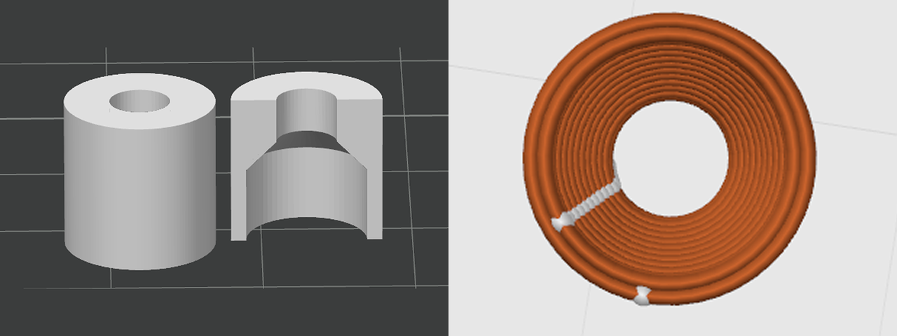
We've shared some useful techniques to fix filament sagging in supportless hole structures. You can improve the print quality of supportless hole structures by designing bridging layers, adding supports, using bridging and designing a chamfer.
Supplementary reading:
[1] Vector 3D, "Avoid Supports, Sacrificial Layers and Bridging with this clever design technique," YouTube, 2018
[2] Bambu Lab Wiki, ''Support Paiting Guide,'' 2025
These articles might help you as well — take a look!
3 Ways to Improve Bridging in Flat Roof Structures
Ways to Reduce Line Detachment in Dome Structures
If this guide sparked ideas or felt familiar, share your thoughts in the comments — let’s chat! Like and save if it helped.


